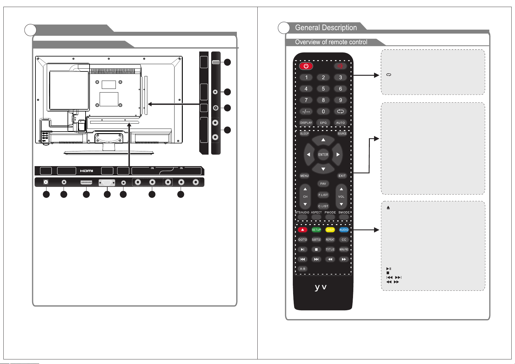
General Description
Overview of back panel
78
POWER: Power on/off button, press once to turn the TV
on and press again to turn the TV off.
MUTE: Press this button to mute or restore sound.
0-9: Select and switch to a channel using 0-9.
-/--: Switch the program digit.
:Switch back and front between the current and
previous channels.
DISPLAY: Display TV information.
EPG: Enter electronic program guide.
AUTO: Adjust the picture automatically in pc mode.
SLEEP: Set the sleep timer.
SOURCE: Press to change signal source.
ENTER: Enter the selected option or perform the selected
operation.
MENU: Press this button to enter the main menu.
EXIT: Exit the OSD (On-screen display).
FAV: Switch between custom set “Favorite List”
F.LIST: Press this key to display the Favorite List mode.
C.LIST: Press this key to display the channel list mode.
CH+/CH-: Change the channel.
VOL+/VOL-: Adjust the volume.
MTS/AUDIO: When stereo program is received, press this
key to switch sound system between mono and stereo.
When SAP program is received, press this button to
switch sound system between mono and SAP
When stereo and SAP program is received, press this key
to switch among mono, stereo and SAP.
Press this key to show the list of audio languages
available for the current channel in ATSC.
ASPECT: Press to adjust picture ratio.
PMODE: Select picture mode.
SMODE: Select sound mode.
: Open/close in DVD mode.
SETUP: DVD system setup.
DISP: Press to display the programs’ information.
AUDIO:Press to change the language of the audio in DVD
mode.
GOTO: Press this button to go to desired position The
player provides 3 search mode.
SUBTITLE: Press to select the subtitle language.
REPEAT: Press to change the playing mode.
CC: Press this key to select the CC, ON or Off mode and CC
on Mute.
TITLE: Press this button can return to the title of the disc.
MENU PBC: Press this button can return to the menu of the
disc, then play the disc from the first track.
: Play / Pause.
: Stop playing.
: Play previous / next media file.
:Play fast backward / forward.
A-B: Repeat play the segment between A and B.
S l ox
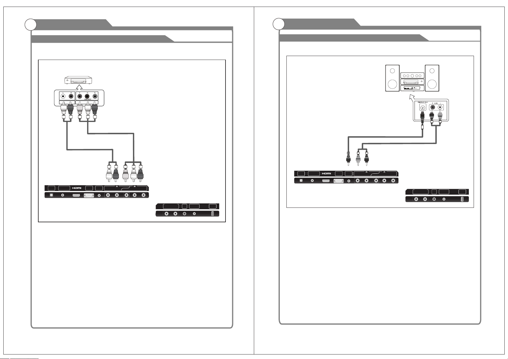
7. YPbPr
Connecting for the Y/Pb/Pr Input in
Component mode.
8. L/R AUDIO output
Audio outputs for external devices.
9. RF
Connect to an antenna or cable
NTSC & ATSC.
10.COAXIAL
Connect to a Digital Audio devices.
11.USB Service port.
1. POWER(DC 10.5-28V) input
2. EARPHONE
Connect a set of phone for private
listening.
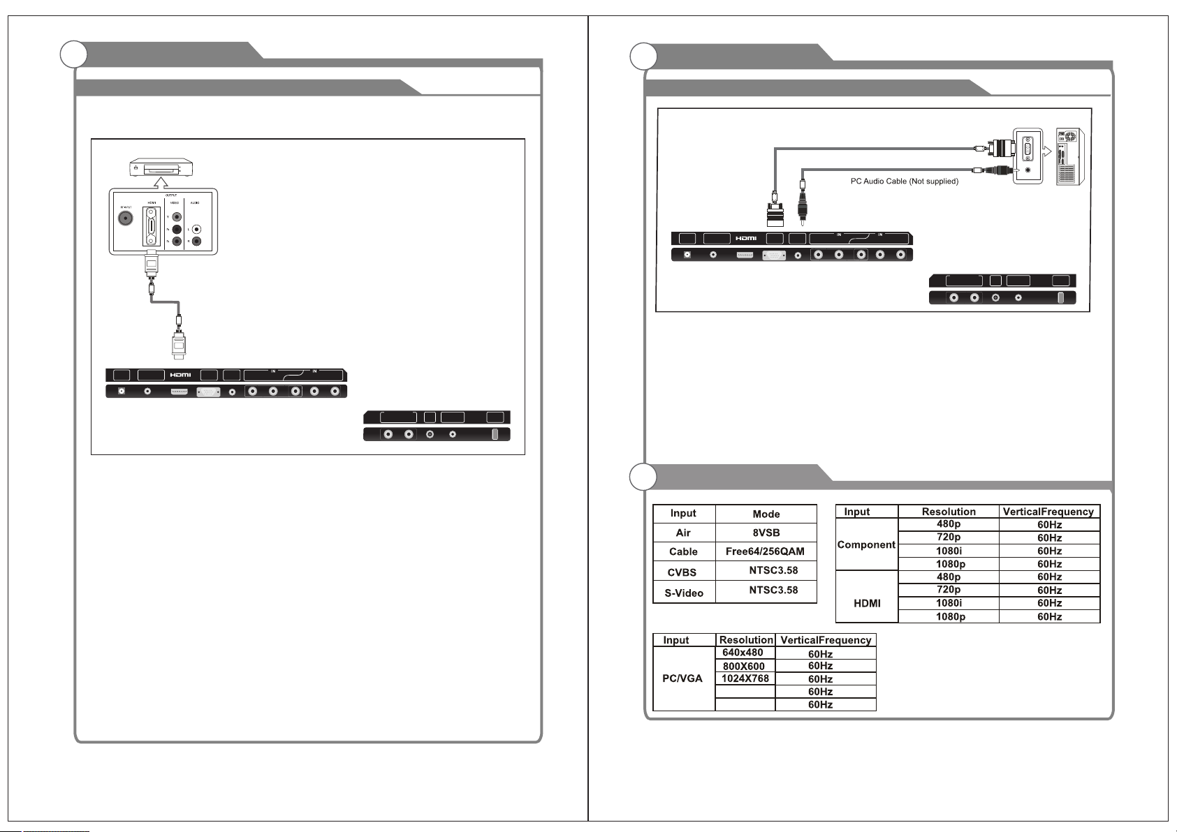
3. HDMI
Connect a device with a HDMI input.
VGA/PC IN4.
Connect to your PC.
5. PC AUDIO
Audio input for external devices.
COMPOSITE VIDEO6.
Video input for external devices, such
as a camcorder or VCR.
32 6 741
EARPHONE
OUT LRY
VIDEO Pb Pr
DC IN VGA
IN
PC
AUDIO
IN
5
RF USB
8
9
10
11
COAXIAL
OUT
LR
AUDIO OUT