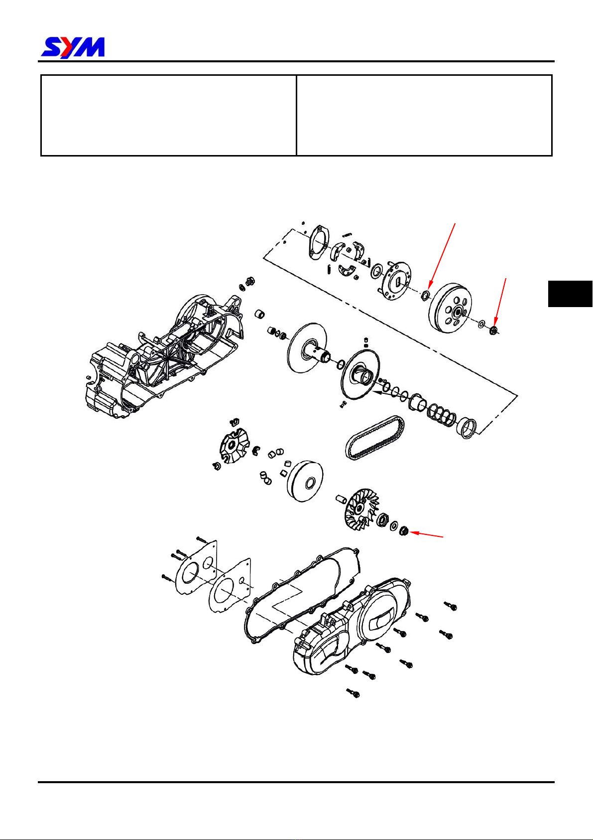
10. V-BELT DRIVING SYSTEM/KICK STARTER
10-2
Maintenance Description
Precautions in Operation
General Information
yDrive face, clutch outer, and driven pulley can be serviced on the motorcycle.
yDriving belt and driving pulley must be free of grease.
Specification Unit:mm
Item Standard value (mm) Limit (mm)
Driving belt width 19.500~20.500 18.500
ID of drive face boss 23.989~24.052 24.060
OD of drive face 23.960~23.974 23.940
OD of roller 17.920~18.080 17.400
ID of clutch outer 125.000~125.200 125.500
Thickness of clutch weight 4.000~4.100 1.200
Free length of driven pulley spring 168.900 163.700
OD of driven pulley 43.65~43.85 43.800
ID of drive face 39.000~39.025 39.060
Torque value
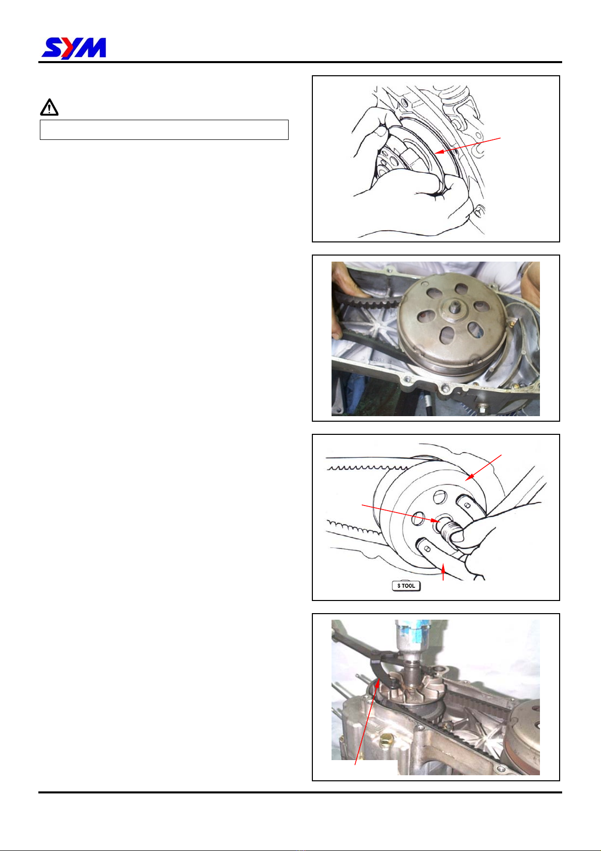
yDriven face nut: 5.0~6.0kgf-m
yClutch outer nut: 5.0~6.0kgf-m
Special Service Tools
Clutch spring compressor: SYM-2301000
Inner bearing puller: SYM-6204002
Clutch nut wrench 39 x 41 mm: SYM-9020200
Universal holder: SYM-2210100
Bearing driver: SYM-9100100
Trouble Diagnosis
Engine can be started but motorcycle can
not be moved
1. Worn driving Belt
2. Worn drive face
3. Worn or damaged clutch weight
4. Broken driven pulley
Shudder or misfire when driving
1. Broken clutch weight
2. Worn clutch weight
Insufficient horsepower or poor high
speed performance
1. Worn driving belt
2. Insufficient spring force of driven pulley
3. Worn roller
4. Driven pulley operation un-smoothly


 Supplementary service manual")