Symbol REDTAIL User manual

REDTAIL - Version 2015 - May Page 1of 28
OPERATIONS MANUAL
for
REDTAIL
54’ Symbol Pilothouse Motoryacht

REDTAIL - Version 2015 - May Page 2of 28
Welcome aboard!
We are happy you have chosen “REDTAIL” for your vacation. We are sure you will enjoy cruising the
enchanted islands of the Pacific Northwest.The stunning geography, birdlife, and incomparable marine life
make this one of the premier vacation destinations in the world.
We trust this manual will help you become
familiar with the boat. If you have questions
about the boat or about places to visit,
please do not hesitate to ask the AYC staff.
Enjoy!
For those who may be curious, about the
name, here is why the name REDTAIL.
We live in Northern California next to 400
acres of open space in the Santa Cruz
Mountains. From our home we enjoy a view
that looks down from a hilltop perch and out
over a majority of the open space. For more
than 20 years we have watched from our deck as families of REDTAIL hawks soar overhead and down below
as they roam out over the pastures and woodlands. They are graceful, adventurous and family oriented
birds. For us, we hope with the boat to soar over the water to reach out to places beyond our deck and do
this gracefully with family and friends with as much of the adventurous spirit displayed by the REDTAIL
hawks we admire at home.
We invite you to share our dream and realize the breathtaking beauty of the Pacific Northwest and the
Salish Sea…

REDTAIL - Version 2015 - May Page 3of 28
TABLE OF CONTENTS
BOAT OPERATION............................................................................................................ 5
Engine Inspection ...................................................................................................................................5
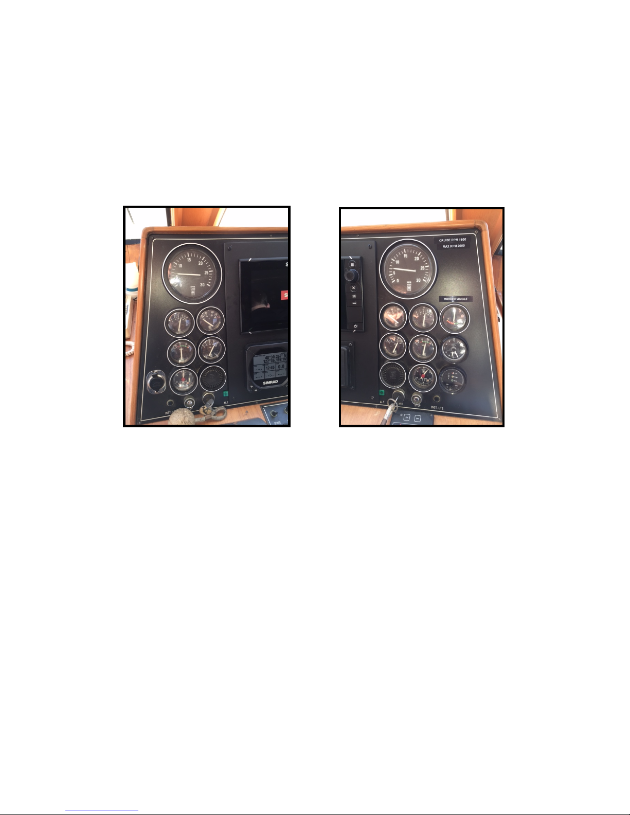
Engine Start-Up ......................................................................................................................................5
Running the Engines ...............................................................................................................................6
Shut-Down .............................................................................................................................................6
Getting Underway ..................................................................................................................................7
Cruising..................................................................................................................................................7
Docking..................................................................................................................................................7
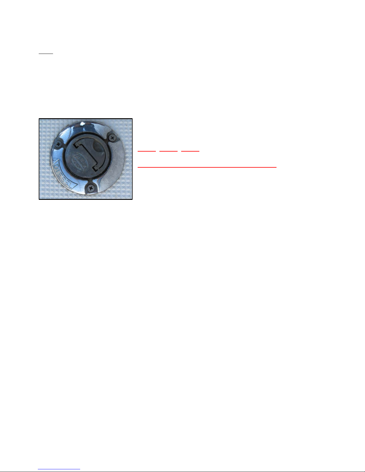
Fueling Up..............................................................................................................................................8
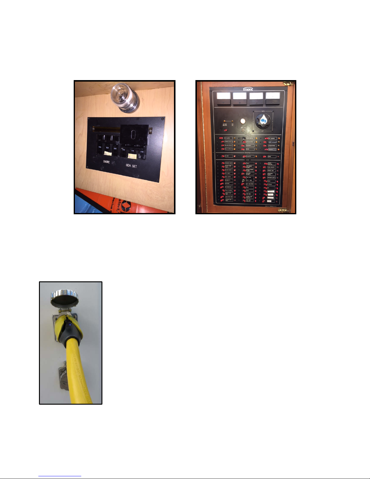
BOAT ELECTRICAL...................................................................................................................................8
110-Volt AC System ................................................................................................................................9
Inverter Power .....................................................................................................................................10
Generator ............................................................................................................................................ 10
CO/Smoke Detectors ............................................................................................................................ 11
House (12-volt) System......................................................................................................................... 11
House Battery Bank & Switch ...............................................................................................................11
SANITATION SYSTEM..................................................................................................... 12
Marine Toilet ....................................................................................................................................... 12
Holding Tank ........................................................................................................................................12
Y-Valve ................................................................................................................................................ 13
WATER SYSTEM ............................................................................................................. 13
Fresh Water Tank(s) ............................................................................................................................. 13
Fresh Water Pressure Pump.................................................................................................................. 14
Hot Water Tank....................................................................................................................................14
Shower ................................................................................................................................................ 14
Sinks & Shower Drains..........................................................................................................................14
GALLEY............................................................................................................................ 14
Stove/oven .......................................................................................................................................... 14
Refrigerator .........................................................................................................................................14
HEATING SYSTEM .......................................................................................................... 15
Diesel Heaters (DC)...............................................................................................................................15
ELECTRONICS................................................................................................................. 15
Multifunction Displays.......................................................................................................................... 16
GPS/Chartplotter .................................................................................................................................16
VHF Radio with AIS Receiver ................................................................................................................. 17
Depth Sounder ..................................................................................................................................... 17
Radar ...................................................................................................................................................17
ENTERTAINMENT SYSTEMS.......................................................................................... 18
The REDTAIL WIFI Network................................................................................................................... 18

REDTAIL - Version 2015 - May Page 4of 28
TV/DVD/ROKU Players .........................................................................................................................18
ANCHORING .................................................................................................................... 19
Mooring Cans....................................................................................................................................... 19
BARBECUE...................................................................................................................... 20
TENDER & OUTBOARD MOTOR.............................................................................................................20
PROPULSION INFORMATION ........................................................................................ 23
THRU-HULL LOCATIONS................................................................................................ 24
ACCOMMODATIONS....................................................................................................... 24
WHAT TO DO IF… ........................................................................................................... 25
ANCHOR CHAIN WON’T COME OUT OF CHAIN LOCKER.......................................................................... 25
ANCHOR FOULED, CAN’T RAISE IT ......................................................................................................... 25
ANCHOR WINDLASS WON’T TURN ........................................................................................................ 25
BATTERIES (HOUSE) KEEP RUNNING DOWN .......................................................................................... 25
ENGINE OVERHEATS ............................................................................................................................. 25
ENGINE WON’T START.......................................................................................................................... 25
ENGINE STARTS THEN SLOWLY DIES...................................................................................................... 26
FOG DELAYS RETURN............................................................................................................................ 26
HEAD WON’T FLUSH.............................................................................................................................26
HIT A FISH NET ..................................................................................................................................... 26
HIT A LOG OR ROCK..............................................................................................................................26
PROPELLER FOULED OR DAMAGED ....................................................................................................... 26
WATER (FRESH) WON’T FLOW ..............................................................................................................26
EMERGENCY PROCEDURES......................................................................................... 26
Protect your lives first! ......................................................................................................................... 26
Hitting a Log, Rock, or Debris ----- Please Don’t! .................................................................................... 27

REDTAIL - Version 2015 - May Page 5of 28
BOAT OPERATION
Engine Inspection
REDTAIL has twin Caterpillar 3208TA 375HP Turbocharged/Aftercooled E-Rated Engines with counter-
rotating screws.
Remember your “WOBBS” every morning: Water (Coolant), Oil, Bilges (Inspect and Pump-out), Belts and
Sea Strainer.
WATER Check the COOLANT level in the expansion tanks; you should see the green coolant in the
expansion tank just below the top of the coolant fill cap.
OIL Check the oil level on both engines. REDTAIL’s engines do not burn much oil so these levels should
remain fairly constant. The level should be in the middle but not over the top of the tic marks on
each dipstick. Please use a paper towel or oil rag, not the dish towels to wipe-off the dipstick! DO
NOT OVERFILL OIL! Don’t add oil unless the oil level is at or below the bottom tic-mark on the
dipstick. Conversely, only add oil (DELO 400LE 30wt) to bring the oil to the top tic mark on the
dipstick.
BILGES REDTAIL’s bilges should always be clean and dry.
BELTS Check the general condition of all BELTS (missing teeth or cracks) and HOSES (checked, cracked,
bulging, or kinked).
SEA STRAINER These are located at the forward end of each engine. Check the SEA STRAINER for debris
(use a flashlight to shine through the bowl). To clean them, close the THRU-HULL, spin the tops of
the sea strainer off, pull and clean the basket, clean out the glass, put the basket back in, screw the
top back on, and OPEN THE THRU-HULL (lever in line with the valve body). After start-up, confirm
that water is exiting exhausts.
And notice any leaks; leaks (water, diesel, oil, hydraulic fluid) are not good!
Engine Start-Up
1. Before starting the engines, do your WOBBS inspection.
2. The engines should be started from the lower helm station.
3. Ensure GEARSHIFTS are in ‘neutral’, or the engines cannot be started because of the “neutral
lockout”.
4. THROTTLES should be run up and down and then brought almost back to the idle position.
5. Insert both keys into the IGNITION SWITCHES.
6. START one engine, let idle for 30 seconds and then start the other.
7. Turn the key clockwise partially until the ENGINE ALARM sounds and pre-heat the engine for at
least 2 seconds.
8. Then turn the key fully clockwise to engage the engine. If the starter does not engage when the
key is turned, move the gearshift lever slightly until you find neutral and try again while turning key.
Note: REDTAIL’s big CAT engines should start easily on the first try. If the engine cranks slowly or fails to
turn over, check the condition of the battery on the ELECTRICAL PANEL.

REDTAIL - Version 2015 - May Page 6of 28
Note: There is no BATTERY PARALLEL SWITCH.
THROTTLE up to 800 rpm on both tachometers. Warm the engines up for about 5-10 minutes before
engaging the transmissions.
GAUGES should read as follows:
Oil pressure about 60-70 PSI or 5 bar. The engine temperature should rise slowly and settle at no more
than 180oF or about 80oC. See pictures below for details of instruments at starting.
Note -- If oil pressure is low, shut down engine, and inspect engine compartment
and look for possible cause (for example, loss of oil.) Caution -- If an engine is
overheating or there is lack of raw water expelled in the engine exhaust, stop the
engine immediately. Recheck the raw water-cooling system to ensure the seacock
is ‘open’ (handle in-line with valve). Next, check the raw water strainer for debris.
Remove the strainer, clean, re-assemble, and reopen the raw water intake valve
(seacock). Restart the engine and re-check water flow from the exhaust. If water is
not flowing properly, the RAW WATER PUMP may need to be serviced. Seek help.
Running the Engines
After the engines have been run up to temperature for a few hours you should “run them hard” for 15-20
minutes at 2300 rpm. Believe-it-or-not, doing this helps the engines, makes them run cleaner, and makes
them run more efficiently.
Shut-Down
Before shutting down, allow the engines ‘idle’ for about 5 minutes to cool them gradually and uniformly.
Usually, this can be accomplished as you enter the marina and head for your slip. The time engaged in
preparing to dock the boat is usually sufficient. Ensure each GEARSHIFT is in the “neutral” position and
each THROTTLE is in the “idle” position. Turn off engines by depressing the start/kill switches next to the
keys then turn the keys to the off position.

REDTAIL - Version 2015 - May Page 7of 28
Getting Underway
DISCONNECT the shore power cord (see 110-Volt next page). Close the PORTHOLES, WINDOWS, and
FORWARD HATCH. Turn on your VHF and electronics. ASSIGN crew members their various positions. Once
outside the marina, idle the engines while crew brings in fenders and lines. Do not exceed 1,200 RPM until
the engines have fully warmed-up; the temperature gauge should indicate 160-180 on both engines.
Cruising
All close quarters maneuvering may take place from either helm station depending upon your skill,
situation, crew, and communications. Communications is critically important. Nothing bespeaks great
seamanship like a crew quietly and competently maneuvering the boat and handling the lines while
docking. No yelling, shouting, or panic; just calm control.
Personally, I always perform close quarters maneuvering from the Pilothouse helm with the Pilothouse
door open to facilitate communications and allow me quick access to the starboard midship dock lines as
appropriate. I also have the “backup” camera display on the starboard MFD at the pilothouse helm station
– handy if you are backing into the slip.
Engage the GEARSHIFTS. Ensure the throttles are in the ‘idle’ position before engaging the gearshifts to
avoid transmission damage. Cruising speed is a maximum of 2,000 RPMS. If you run at 1,600 RPMS you
will easily cruise at 10 knots and use only 12 gallons of diesel per hour; this is considered efficient cruising
speed. If you travel a bit slower, your fuel efficiency will increase. Your speed will vary depending upon
the weight, load, sea, current, and weather conditions. At these speeds, the TRIM TABS do not have much
effect. If you want to run faster (up to 2000 rpm) the TRIM TABS can be put in the “bow down” position to
provide for a better and more efficient ride (though still consuming more fuel than travelling at lower
rpms).
Docking
During docking, use the Pilothouse helm for greater visibility to the stern. Have your crew make ready the
lines and fenders in advance and give clear instructions on how you will be docking. Often times your crew
will need to step off from the swim step with the stern line. Another crew member will need to be at the
bow or mid-ships to hand over the next lines.
Rock TRIM TAB switches to the ‘bow up’ position (8 to 10 seconds) to make slow-speed backing and turning
easier. While moving slowly to the dock or mooring location, center the WHEEL (e.g. rudders straight) and
use only the GEARSHIFTS and THROTTLES to maneuver the boat.
A word of experienced advice…Use one of the longer black dock lines amidships. Make it fast to the
boat’s midship cleat. When you come alongside a pier, slip, or dock you can lasso the dock cleat and then
make fast the bitter end to the midship cleat (so you essentially have a loop). Now the helmsperson can
take their time as you have the boat under control. Power forward slowly and the boat will move forward
and sideways towards the dock or you can accomplish the same maneuver in reverse.
There are bow thruster controls in the pilothouse and on the flybridge (new 2015). The new Vetus bow
thruster is meant to augment and help control the bow of the boat. Warning – this is a 57,000lbs boat, the
bow thruster will not have a large effect – do not count on it to move the boat sideways against current or
wind.

REDTAIL - Version 2015 - May Page 8of 28
To turn “ON” the Thruster, on the thruster control in the pilothouse or on the bridge, press the on button
twice. The boat’s bow will move in the direction of the arrow you press. When you are done, please turn
the thruster off.
Fueling Up
OPEN FILLER CAP(S) located on the port and starboard side decks. Note that these filler caps do not
require a DECK FITTING KEY.Be very careful as the chain securing the caps to the boat often break – do
not lose one of these caps overboard, they are expensive to replace and we don’t want any water in our
diesel.
MAKE SURE YOU HAVE THE RIGHT FUEL!
DIESEL! DIESEL! DIESEL!
MAKE SURE IT IS GOING INTO THE RIGHT DECK FILL!
DOUBLE-CHECK!
Before pumping, have an oil/fuel sorbs handy to soak up spilled fuel. You should have a rough idea of the
number of gallons of DIESEL you will need by the engine hour indicator or the sight glasses located on the
forward end of each fuel tank in the engine room. Also periodically have someone look at the sight glasses
to see your progress. Note that you will have to open the ball-valves at the top & bottom of the sight
glasses to allow the fuel level to be accurately read. When full, the fuel level in the sight gauges should be
slightly above the top of the metal indicator gauges. Watch both sight gauges in the engine room as both
tanks will fill while fueling one side.
Place the DIESEL nozzle into the tank opening, pump slowly and evenly, and note the sound of the fuel flow.
Pumping too fast may not allow enough time for air to escape, which may result in spouting from the tank
opening. As the tank fills, the sound will rise in pitch or gurgle; the sound may indicate that the tank is
nearly full. Pay attention to the TANK OVERFLOW VENT on the outside of the hull near the fuel fill opening.
Pay attention to the sight glasses; do not over fill. Top off carefully, and be prepared to catch spilled fuel.
Spillage may result in a nasty fine from law enforcement.
Replace each tank cap. Turn on blower before starting engines. Caution -- Clean up splatter and spillage
immediately for environmental and health reasons. Wash hands with soap and water thoroughly. Also,
note that diesel on fiberglass when mixed with salt water can be extremely slippery.
Fill the DIESEL fuel tanks FULL, but do not overfill.
BOAT ELECTRICAL
The electrical system is divided into two distribution systems: 110-volt AC and 12-volt DC.
The systems are controlled from the AC/DC ELECTRICAL PANEL located in the stairwell from the Pilothouse
to the staterooms and the SHIP-SHORE MAIN POWER SOURCE SWITCH found behind the door just below
the electrical panel. When not connected to shore power, batteries are providing all power. Therefore,

REDTAIL - Version 2015 - May Page 9of 28
monitor the use of onboard electricity carefully with your amp meter located on the top of the electrical
panel, and turn off electrical devices that are not needed.
See pictures for more details.
Most breakers are labeled by colored dots. Green signifies “usually on”. Red is “usually off”.Blue dots are
water pressure or water-related like pumps. Yellow signifies electronics or items to use cautiously. No dots
are breakers signify irregular use or use with discretion.
110-Volt AC System
SHORE POWER supports all AC equipment and receptacles on board, as well as the battery chargers.
To connect to shore power, plug the 50 amp or 30 amp Marinco EEL POWER
CORD into the boat (note receptacles are in the cockpit first and then into the
dock receptacle. Check the power rating/plug size of the nearest dock receptacle
(that is 50 amp, 30 amp, 20 amp, or 15 amp). If necessary, add a CORD ADAPTER
located in the forward end of the engine room by the workbench. NOTE, never
plug the shore 50 amp supply into the boat’s 30 amp input.Once all connections
are fast then turn the dock power circuit breaker on. Cords coming off the boat
can be wrapped loosely around the line to keep them out of the water. Salt
water and power cords don’t mix well!
At the ELECTRICAL PANEL, flip the SHORE CIRCUIT AC MAIN BREAKER on. Check
for reverse polarity. Then turn on appropriate breakers for battery charger,
Inverter, refrigeration, and water heater. Watch your amp meter for load. If the
load exceeds amperage, you will pop your breaker. If this occurs, wait to turn on
one of your systems (i.e. water heater) until your use of amperage drops.
If your outlets fail to work, check your GFIs to make sure that they have not been tripped.

REDTAIL - Version 2015 - May Page 10 of 28
Inverter Power
The INVERTER provides AC power to the 110-volt receptacle plugs (i.e. the microwave oven) when the boat
is disconnected from shore power. REDTAIL has a charger/inverter (Magnum) and a charger (Blue Sea).
The inverter does not provide power to the water heater or the battery charger. Your inverter panels are
located just to starboard of the aft companionway sliding door each with an on/off switch. Make certain
that they are on.
The actual chargers and inverter are located on the aft bulkhead
in the engine room.
The inverter’s power source is the DC house or inverter batteries
(3 8D wet cell batteries) located between the drive shafts under
the engine room floor. The quantity of DC power is limited to
the capacity of these batteries... Therefore, running hair dryers,
toaster, coffeepots, space heater, etc. and will quickly discharge
the house/inverter batteries. Use these items VERY SPARINGLY!
Monitor your battery usage very carefully!
When connected to shore power, the inverter automatically
becomes a battery charger for the 12-volt HOUSE BATTERIES.
Should you detect the inverter failing to charge the house
batteries, check the circuit breaker in the AC panel. And the
inverter control panel. Also, there is usually a circuit breakers
located on top of the inverter box.
The Blue Sea battery charger is dedicated to charging the
GENERATOR and ENGINE START batteries.
Generator
To start your GENERATOR, first check that your generator’s fluids are topped off and the raw water intake is
open. The generator controls are located below and to the left of the Pilothouse helm station (see picture).
First pre-heat the generator for about 30 seconds. Then while still pre-
heating turn the switch to start. Hold the switch in that position while
the generator catches. (About 5-10 seconds).
Make sure water and exhaust is
exiting the generator exhaust at
the port aft portion of the hull.
(See picture).
After generator is running, turn
your SHIP-SHORE MAIN POWER
SOURCE SWITCH to “GEN SET”.
Then turn on AC systems as you
would on shore power one
system at a time.

REDTAIL - Version 2015 - May Page 11 of 28
To turn the generator off, first take off the load by turning off AC breakers. Then turn the SHIP-SHORE MAIN
POWER SOURCE SWITCH to “SHORE”. Lastly kill the generator by switching generator switch to “off” until it
stops.
CO/Smoke Detectors
There are 2 combination Carbon Monoxide (CO)/Smoke Detectors onboard REDTAIL. One is located in the
engine room between the 2 HALON fire suppression canisters, and the other is located in the hallway just
outside the guest head. Both are battery powered by 2 AA batteries and are therefore independent of any
house electrical system. You should check these by depressing the test button to make sure they are
operable. If not, replace the batteries.
The alarms are loud and have a voice message letting you know whether the problem is fire or CO related.
House (12-volt) System
3 battery banks support 12-volt DC power:
1) Engines – 1 8D starting battery each (in engine room)
2) Genset - 1 8D starting battery (aft of port water tank in lazarette next to the generator)
3) House/Inverter - 3 8D deep-cycle batteries (between drive shafts below floor)
There are 4 primary BATTERY SWITCHES which are located on the aft wall of the engine room just to port of
the entryway stairs. Normally, leave all switches on the “ON” position.
Your 12 volt panel shows all the systems supported by your batteries. Primarily you will be turning on the
breakers for your lights, water pressure, electronics, instrumentation, etc. Bilge and the shower sump
pumps should always be left on.
House Battery Bank & Switch
The HOUSE BATTERY BANK provides power for all DC systems, except the engines and 3 automatic bilge
pumps. When disconnected from shore power, all 12-volt devices drain the house battery. Use devices as
needed. The DC voltmeter on the DC panel can be switched between Port, Starboard, and House Battery
banks to measure charging or resting battery voltages.
When a battery bank is being charged, the voltage will read from about 13.1 volts to 14.4 volts depending
upon state-of-charge of the battery bank. When the battery bank is at rest, (not being charged), the
voltmeter can give a rough indication of the state-of-charge
of the battery bank.
All batteries are charged by the engine ALTERNATORS while
underway. The engine/house batteries are charged by the
BATTERY CHARGER when connected to shore power. Ensure
the Battery Charger and Inverter circuit breakers at the
electrical panel are ON. The GENERATOR will also charge the
batteries.
Voltage (Wet Cell Battery)
Battery State
12.65 volts
100%
12.47 volts
75%
12.25 volts
50%
11.95 volts
25%
11.70 volts
0%

REDTAIL - Version 2015 - May Page 12 of 28
SANITATION SYSTEM
Marine Toilet
It is important that every member of the crew be informed on the proper use of the MARINE TOILET. The
valves, openings, and pumps are small and may clog easily. If the toilet clogs, it is YOUR RESONSIBILITY!
Always pump the head for children, so you can make sure nothing foreign is being flushed.
Caution – Never put paper towels, tampons, Kleenex, sanitary napkins, household toilet paper, or food into
the marine toilet. Use only the special dissolving marine toilet tissue provided by AYC.
Note both toilets are electric, macerate at the head itself, and flush with FRESH WATER. This is ideal as it
prevents most causes of clogging toilets presuming you follow the instructions for not putting inappropriate
objects into it.
In both heads you will find a small switch panel beside each toilet. There are 4
switches on the panel (Fill, Empty, Quick Flush, and Flush). These do exactly what
they state.
To use the toilet, make sure there is water in the bowl. After using the toilet, hit the
appropriate button for “flush” or “quick flush”. Make sure the bowl empties. There
will be a small amount of water left in the bowl and this is as it should be.
Clean the toilet as necessary.
There is no direct overboard discharge on REDTAIL. All effluent goes directly into the 2 holding tanks.
Holding Tank
REDTAIL does not smell like “old-head”. The entire sanitation system is new and top-of-the-line.
There are 2 roto-molded polyethylene sanitation HOLDING TANKS which hold approximately 35 gallons
each. Be aware of the rate of waste production (about 1/2 gallon per flush). With an overfilled tank, it is
possible to break a hose, clog a vent, or burst the tank. The result will be indescribable catastrophe and an
EXPENSIVE FIX to you. Empty the tank EVERY OTHER DAY to avoid this problem.
The HOLDING TANKS are located under the VIP berth and under the Master berth. Some may be subject to
a visual check with a flashlight or the “watermelon” test by thumping it. Both tanks are polyethylene roto-
molded tanks. You can hold a flashlight up to the side and visually see the level of effluent. There is a
tank watch warning light but DO NOT trust or rely upon this as they often get clogged.
The holding tank is emptied in one of two ways:
#1 At the Marine Pump-Out Station, remove the WASTE CAP located on the midships side
decks, port and starboard. Insert the pump-out nozzle into the waste opening. Double-
check your deck fitting! Turn on pump and open valve located on handle. When pumping
is finished, close lever on handle and turn off pump. Remove SLOWLY from deck fitting.

REDTAIL - Version 2015 - May Page 13 of 28
If there is a fresh water hose on the dock, rinse the tank by adding 2 minutes of water into tank. Then re-
pump to leave the tank rinsed for the next charter. This also eliminates head odors.
#2 The tank’s contents can be discharged with the OVERBOARD MACERATOR pump, but only in Canadian
waters.
To empty the forward holding tank overboard:
1. The forward holding tank THRU-HULL is located in the engine room, forward end, starboard side.
The handle is aligned with the THRU-HULL when the valve is open.
2. Turn ON the macerator pump switch on the main DC electrical panel labeled “Spare”.
3. WATCH the gauge in the VIP Head and/or LISTEN to the pump. When the gauge indicates or the
sound the pump makes changes pitch the tank is empty.
4. Turn the macerator pump OFF.
5. Close the THRU-HULL.
To empty the aft holding tank overboard:
1. The forward holding tank THRU-HULL is located in the engine room, forward end, port side
between the fuel tank and the forward bulhead. The handle is aligned with the THRU-HULL when
the valve is open.
2. Turn ON the macerator pump switch on the main DC electrical panel labeled “Holding Tank Pump”.
3. WATCH the gauge in the Master Head and/or LISTEN to the pump. When the gauge indicates or
the sound the pump makes changes pitch the tank is empty.
4. Turn the macerator pump OFF.
5. Close the THRU-HULL.
Y-Valve
There is no Y-VALVE.
WATER SYSTEM
Fresh Water Tank(s)
The FRESH WATER TANKs hold 230 gallons in two 115 gallons stainless water tanks located in the lazarette.
Observe the water level by the site-tubes inconveniently located on the forward sides of each water tank.
The port tank is easier to see than the starboard one. Both tanks are interconnected so you can use the
port tank site-tube to monitor the water level in both tanks.
To refill the tank
1. Rinse off the deck around the WATER CAP, located on the starboard side deck.
2. Remove the WATER CAP.
3. Fill the tanks. Use a clean hose (There is a 50’ green hose in the lazarette we use for this purpose.
4. Please have someone in the lazarette observing the water level. DO NOT OVERFILL the water
tanks. Fill them to just under full. If you hear thumping/popping noises, that is the water tanks
“canning”, meaning the water is too full.
Avoid flushing debris from the deck into the tank opening. NEVER fill water and diesel at the same time!

REDTAIL - Version 2015 - May Page 14 of 28
Fresh Water Pressure Pump
The WATER PRESSURE PUMP is located on the floor just forward of the hot water tank in the engine room.
It is a brand new ShurFlow 5GPM pump. Activate the pump at the DC panel by turning on the breaker.
The pump will automatically come on when it senses a pressure drop. There is an accumulator tank to
keep the running of this pump to a minimum. If the water pump continues to run, you are either out of
water or might have an air lock and need to bleed the system by opening up a faucet. If you run out of
water SHUT OFF YOUR HOT WATER HEATER on the AC panel. Serious damage can occur!
Hot Water Tank
The HOT WATER HEATER has a 20 gallon capacity tank and is available when connected to shore power or
via a heat exchanger from the engine when underway. To use on shore power, flip on the water heater
circuit breaker on the AC electrical panel. Do not use the water heater if the water tank level is very low.
The water heater is located just forward of the starboard engine.
Shower
Before taking a SHOWER, make sure water pressure and shower sump breakers are on. Take only very
short “boat” showers (turning off water between soaping up and rinsing). To keep shower tidy wipe down
the shower stall and floor. There is a squeegee blade in each shower, please use if after you are done. This
keeps the boat drier and reduces mildew. Check for accumulation of hair in the shower and sink drains.
An additional FRESH WATER SHOWER is located in the cockpit. Ensure that the faucets and nozzle are
completely off after use.
A pressured RAW WATER WASHDOWN is available from a hose spigot on the starboard bow. To activate,
flip the PUMP ROCKER SWITCH located on the DC electrical panel. DO NOT USE the green 50’ fresh water
hose. There is a hose located in the bow locker for this purpose. After use, turn the switch off to prevent
pump burn out, and ensure no object leans on the switch to turn it on accidentally.
Sinks & Shower Drains
Waste water from the sinks and showers drains overboard through various thru-hulls located in the engine
room, forward on the port side.
GALLEY
The boat has an open U-shaped galley with nice counter space and easy access to stored items. In
addition, with this set up you are not blocked off from the rest of the space, so when you are
cooking, you can remain part of the conversation.
Stove/oven
The stove/oven is electric and runs either when on shore power
or when on the generator. Turn on the “stove” breaker on the
AC panel.
Refrigerator
The REFRIGERATOR is dual voltage (12-volt and 110-volt power).
It will automatically use 110-volt power when the shore power
is connected; otherwise, it will operate on 12-volt power.

REDTAIL - Version 2015 - May Page 15 of 28
Monitor the use of the refrigerator when the engines are not charging the 12-volt battery system. The local
power switch is located below the front door. It can be turned down to the lowest position when anchored
or moored or turned off when turning in for the night.
Other items included in the galley setup:
•Microwave
•Blender with chopper attachment
•Coffee Pot
•Knife Sharpener
•Small Fan
•Iron – Master Cabin Closet
•Electric Fryer
•Electric Griddle
•Crockpot
•Keurig
•Wine Cooler
HEATING SYSTEM
Diesel Heaters (DC)
There are 2 Espar Airtronic D5 18,800BTU Diesel Forced Air heaters onboard REDTAIL. These can generate
enough heat to make the boat toasty warm even in the coldest winters. When operating on high, each
furnace will consume about 0.15 Gallons of diesel per hour. These are very efficient and economical. If
you operate them on “high” you will have a sauna aboard, about half way seems to keep REDTAIL warm
even on the coldest nights.
The furnace for the staterooms is located under the floor, starboard side in the VIP
stateroom. The thermostat that controls this is located in the Master cabin just by
the head-board and to port.
The furnace for the main saloon, galley, and pilothouse is located in the engine
room just forward of the port fuel tank. The thermostat is located just to starboard of the pilothouse
steering wheel.
Check The furnace EXHAUST PORTS located just outboard of the 2 furnaces. Note that the exhaust is HOT!
Check to make sure that there are no obstructions such as fenders or lines. Do not block this opening when
operating the furnace. Heat will damage fiberglass or rubber. Once it is on, allow it to run for at least 15
minutes before turning it off. Turn ‘off’ the furnace heater by turning each thermostat switch to the “off
position”.
ELECTRONICS
All navigation electronics are new as of 2014/2015. There is a complete
setup of 3 SIMRAD NSS EVO2 multifunction displays, GPS, depth/fish
finders, 4G Broadband Radar, Wind
Instrumentation, ICOM AIS receiver, ICOM
VHFs radios, Cameras, and a ComNav
AutoPilot.
There is also a Nav Laptop Computer with

REDTAIL - Version 2015 - May Page 16 of 28
RosePoint Coastal Explorer in the Pilothouse with its own GPS antenna.
All electronic manuals are located in the pilothouse under the settee.There are lots of manuals. Please
do not reprogram all of these electronics.
Multifunction Displays
There are 2 displays in the pilothouse and 1 on the flybridge. These are all SIMRAD NSS EVO2 and they are
all networked together. The “Master” is the port display in the pilothouse. This display shares the
Navionics Platinum Plus cartography to the other units. Turn this display on first. Then turn on any other
displays.
Here is the sequence I follow when starting up
the Nav Electronics:
1. Turn on the breakers in the main DC
electrical panel.
a. Horn
b. Wipers
c. Trim Tabs
d. Rudder Indicator
e. Navigation Lights
f. Radar
g. Autopilot
h. VHF
i. N2K System
j. P/H Displays
k. Cameras
2. Turn on the port MFD, then turn on the other MFDs.
3. Setup the Chart display on the port MFD. You can choose to overlay the radar image on the chart
if you so wish.
4. On the starboard MFD setup a split screen with the Radar and Depth/Fish Finder on the starboard
display.
5. Make sure the dedicated IS40 displays for depth, speed, wind, etc. are working.
6. Turn on the VHF (if not already on).
7. Turn on the Nav Laptop Computer and choose your preferred cartography (raster, vector, aerial
photography, topographical, etc.).
You are now set and ready to go.
GPS/Chartplotter
As mentioned, there is 1 SIMRAD dedicated GPS sensor and 1 Nav Computer dedicated GPS sensor. The
GPS information is integrated with and displays on the MFDs and the Nav Computer.
The NAV COMPUTER is a Dell laptop with a USB GPS receiver; it can be found in the pilothouse forward of
the settee. The navigation software is the current version of RosePoint Coastal Explorer running on
Windows 7 Professional. On this Nav Computer there is also a PDF of the current copy of NAVIGATION
RULES International – Inland (COMDTINST M16672.2D).

REDTAIL - Version 2015 - May Page 17 of 28
This is a navigational tool, not a gaming computer. Please do not play games, install any software, connect
it to any network or otherwise do anything to it other than use it for navigation. The laptop is plugged into
the 110V system on the boat so to power it you will want the inverter “ON”.
Coastal Explorer is a very intuitive chartplotter. It has 2 modes; Cruising & Planning. Cruising mode is the
mode you will be in when underway. Planning mode is what you will use if you want to layout waypoints,
routes, and otherwise plan your voyage in advance. I strongly recommend that you preplan your routes.
There is no manual for this application, but there is a help function built into it.
VHF Radio with AIS Receiver
There are 2 fixed-mount ICOM VHF RADIOS, one at each helm station. For the fixed-mount VHF radios
there is a circuit breaker on the DC electrical panel – make sure this is turned “ON”.
Both fixed-mount VHF radios have DSC and the MMSI numbers have been
properly registered.
The CALL SIGN is: WDH7361
Note that the pilothouse VHF has AIS and it is integrated with the
multifunction displays.
Always monitor channel 16 while underway.
Depth Sounder
There are 2 DEPTH SOUNDERS, one is Depth/Speed through the water/Water Temperature with a digital
display (SIMRAD IS40) and the other is a graphic display available on all helm station MFDs.
All depth sounders are “zeroed” for the water line, not water under the keel. REDTAIL draws about 5’ so
please be advised that anything under 10’ (3 meters or 1.5 fathoms) is risky. Be prudent and be careful.
Stay in deeper waters and mind your tides.
Remember to ALWAYS consult your charts for depth!
Radar
To operate the SIMRAD Broadband 4G RADAR once the MFDs are powered up; select the Radar menu and
press “TRANSMIT”. It will take about 10 seconds for the RADAR for the RADAR to display on the MFD. You
can then overlay on the Chart screen and/or view it in its own screen. I recommend both.
Remember you are not allowed to travel in FOG or in serious wind conditions.

REDTAIL - Version 2015 - May Page 18 of 28
ENTERTAINMENT SYSTEMS
The REDTAIL WIFI Network
REDTAIL has a complete WIFI network on the boat and a high-gain WIFI antenna to reach out to connect to
any WIFI networks in the area.
The idea is that all local devices connect to the REDTIAL WIFI network and the REDTAIL WIFI Network
connects to a shore-based WIFI network for Internet access.
To use the REDTAIL WIFI network:
1. Make sure the “WIFI” circuit breaker is “on”. This is located on the main DC Electrical Panel.
2. Use any laptop or WIFI device you have (NOT THE NAV COMPUTER) to connect the Wireless
network called “REDTAIL”.
3. Then open your browser and type: http://192.168.89.1/ in the address bar.
4. You will see a listing of all the WIFI networks that are in range and their relative signal strengths.
At this point you have 2 options. If you see a network called BBX you can connect to this as
REDTAIL has an annual contract with this service. BBX can be found in many of the marinas in the
San Juan and Gulf Islands. Select BBX. You will see that it connects.
5. Open another browser window, go to any website and you will be directed to log into the BBX
account. The Username is “REDTAIL” and the password is “kpqao99169”
If you don’t see BBX, then pick any open (no password required) WIFI network with a strong signal.
6. Once you have connected the REDTAIL WIFI network to the shore-side WIFI network you will have
Internet access on your devices and the ROKU TV player.
7. NOTE: Internet bandwidth in marinas is a function of demand. In the summer months the demand
can be very high, meaning that you may not always have great bandwidth. If your Internet
connection is too slow, try a different shore-side WIFI network or just go boating instead.
TV/DVD/ROKU Players
In the main saloon is the video entertainment system which consists of a 40” LED TV (HD 1080p), and Blu-
Ray DVD Player, the ROKU3 Streaming media player, an Xbox player, and a Polk Audio soundbar and
subwoofer. These all run on AC power from the Main Saloon circuit.
The remote controls for these devices and the devices themselves are
located in the cabinet under the TV.
To display these devices on the TV, change the inputs as follows:
•HDMI-1 is the ROKU3 player
•HDMI-2 is the Blu-Ray DV player
•HDMI-3 is the Xbox 360 Elite player
There is also a TV/DVD player in the guest/VIP stateroom forward. It is an all-in-one unit and you can move
it to other cabins as needed, this requires AC power to operate.
Note: there is a collection of DVD’s on board for your use. Please be sure to leave them for the next guest.

REDTAIL - Version 2015 - May Page 19 of 28
ANCHORING
The primary WORKING ANCHOR is a 90lb CQR-type and is attached to
260ft 3/8 BBB chain and 100ft ¾ nylon line passed through the deck from
the ANCHOR LOCKER in the bow. The locker can be accessed through
the port bow locker.
The WINDLASS is a vertical capstan MUIR 2500 with rope and chain
gypsy. The POWER SWITCH is located below the pilothouse helm station
to port of the steering wheel. There are “up” and “down” controls just
aft of the windlass. Make sure that switch is turned to the “ON”
position. At the bow, tap gently on the “down” foot control to lower the anchor. If necessary, guide the
anchor over the anchor roller to prevent binding on the pulpit. Initially you may have to push the anchor
over the roller until the weight of the anchor and chain is sufficient to pay itself out.
Let out sufficient ANCHOR RODE (you’ve got a total of 260’ of chain and 100’ nylon rode) before setting the
anchor. Colored markers (yellow paint) are placed every 30feet on the chain; the nylon rode is unmarked.
If the anchorage is crowded put down at least a 3 to 1 scope (75 feet for 20 feet of water – remember the
bow is 6’ above the waterline), Attach the bridle (either the single or double bridle) to the Samson post or
the bow cleats then back the anchor in with a short burst from one engine. Let out additional scope
depending upon conditions.
NEVER, just let the anchor tension be taken solely by the windlass. That’s not what it was built for; use a
bridal on the Samson post. Be aware of your swing radius as compared to other boats and objects around
you. You might want to set an anchor alarm to alert you should REDTAIL drag.
Don’t forget to turn “OFF” the WINDLASS POWER SWITCH when you are done.
Before raising the anchor, ALWAYS start the engines as it uses large amounts of power. Turn “on” the
WINDLASS SWITCH. Bump the engine controls forward and as the boat moves toward the anchor, press
the “up” control to take up slack chain/line. Don’t run over the anchor chain. Give the windlass short
rests as you are pulling it up. Place yourself in position to guide the anchor onto the roller. As the anchor
rises, be careful not to allow it to swing against the hull.
If the windlass motor does not work, there is a manual handle (looks like a winch handle) in the aft cockpit
locker just to port of the saloon door.
We suggest that you use the wash-down pump at the bow to wash the rode and anchor as you are
retrieving it and before storing in the anchor locker. This helps keep it from smelling in the forward locker.
Turn “off” the WINDLASS POWER SWITCH.
Mooring Cans
The State Park Sticker on your vessel allows you to pick up the MOORING CANS in the parks for free. You
only need to register at the kiosk usually located at the heads of the docks. Mooring cans have a metal
triangle at the top upon which is a metal ring. The metal ring is attached to the chain which secures your
boat. IT IS VERY HEAVY. The strongest member of your crew should be picked for this job.

REDTAIL - Version 2015 - May Page 20 of 28
Come up to the CAN into the wind as you would for anchoring. Have crew members on the bow, one with
a boat hook and one with a mooring line secured like a bow line. As you are coming slowly up to the can
have the crew holding the boat hook point at the can with the hook so the skipper always knows where it
is. Hook the can and bring the ring up to the boat to allow the second crew to thread the ring with the line.
Release the hold with the boat hook. If your mooring line is led out the starboard chock bring the end of
the line back through the port side. You will essentially create a bridle with about 10 feet of slack from the
chalk to the can.
BARBECUE
The BARBECUE is stored in the Lazarette.
When you wish to cook with the barbecue, place the barbecue on the back deck with foil underneath to
catch any drips. Attach a PROPANE BOTTLE to the REGULATOR found. Propane bottles are provided by
AYC and should be stored in the cockpit cabinet. Carefully light the unit, preferably with long-stem butane
lighter. The barbecue generates a lot of heat and cooks hot and fast. Ensure gasoline and flammable
materials are not near the barbecue.
CLEAN the Barbecue before storing it. A quick wipe down to remove grease will go a long way towards
making your use of it more pleasurable and less messy. Store the barbecue unit back in the lazarrette.
Caution -- For safety reasons, do not store an opened propane bottle within the salon or engine
compartment. Chances are these will leak slightly once opened and propane gas could settle into low
spaces. Store these bottles in the cockpit cabinet. Please do not place the bottles on the teak deck without
something underneath; the bottles can stain the wood. Note: Propane bottles are stocked by AYC.
TENDER & OUTBOARD MOTOR
The Apex 11’, 5-person TENDER with a 25hp Nissan engine is stored on the swim platform, aft. The tender
has a capacity of about 1,050 pounds (motor, equipment, and 5 adult people). The davit is a
Roskelley/Olsson Transom Fork-davit with an 800lbs capacity.
DO NOT TOW the Tender, lift it with the davits. This system is so easy, quick, and safe to use there is no
reason to tow the tender. Towing reduces your speed by ½ a knot, decreases fuel economy, puts
tremendous strain on the tender’s tow eye, and you run the risk of flipping the tender in a wake or other
wave. Just lift it and then these are all non-issues.
To deploy the tender: remove & stow the cover, Make sure the tender
painter is cleated to the REDTAIL, Remove all other straps. Using the
control unit (stored in a bag that hangs just inside the Engine access door
and plugs into the round outlet just to the port side of the swim platform
door in the aft cockpit) raise the davits a few inches. Then disconnect
the safety keeper carabineer on the starboard side compression post.
Then lower the tender in to the water. Disconnect the sling and you are
ready to go.
Table of contents