Introduction
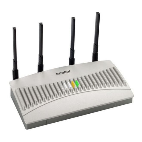
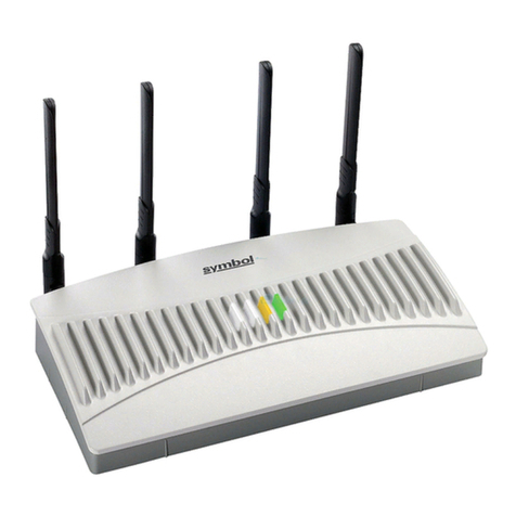
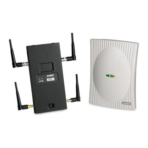
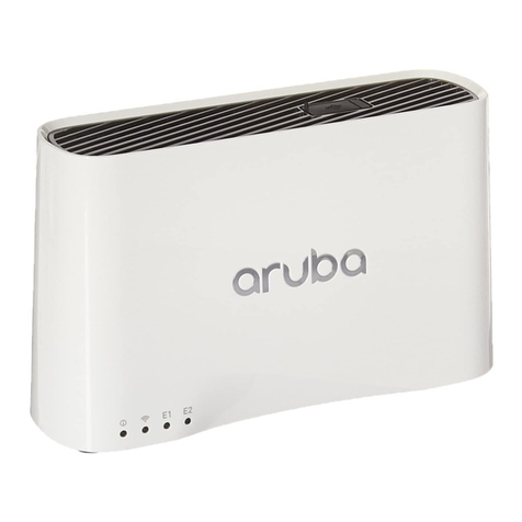
The AP-41X1-1050 Direct Sequence access point provides a bridge between
Ethernet wired LANs and Spectrum24 wireless networks. The access point
provides access between Ethernet wired networks and radio-equipped mobile
units (MUs). MUs include all Symbol Spectrum24 terminals, scanners,
PC Cards, phones, third-party devices and other equipment.
For additional installation and configuration information, go to
www.symbol.com and search for the Spectrum24 AP-41X1 HR Access Point
Product Reference Guide.
Hardware Installation
Precautions
Before installing the access point verify the following:
• The location of the unit is dry and dust free. Install in wet or dusty areas
only with additional protection. Contact a Symbol representative for
more information.
• The installation environment is between -20°C and 55°C.
• AP can be installed on a different subnet if mobile IP is enabled.
Requirements
The minimum installation requirements for a single-cell, peer-to-peer
network are:
• Power outlet
• Access point
• Null modem serial cable.
Note: Use and test the access point with an associated MU.
Network Connection
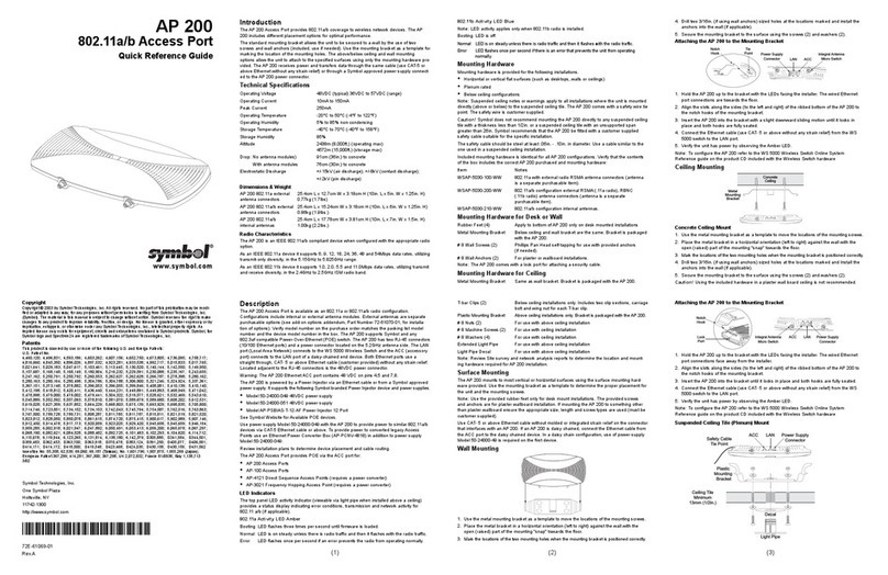
Locate connectors for Ethernet and power on the back of the access point.
Ethernet configurations vary according to the environment.
10Base-T UTP
Use a 10Base-T connection for multiple access points or an access point
attached to a wired UTP Ethernet hub. Normal 10Base-T limitations apply.
1. Plug the data cable RJ-45 connector into the AP RJ-45 connector.
2. Plug the other end of the data cable into the LAN access port (possibly
a hub or wall connection.)
3. Add additional access points as needed.
Mounting the Access Point
The access point rests on a flat surface or attaches to any hard, flat, stable
surface. Use the access point mounting kit to secure the access point.
Select an access point mounting option based on its intended
operating environment.
• Resting flat
The access point rests on four rubber pads on the underside of the AP.
Place on a surface clear of debris and away from office traffic.
• Attached to the wall
The access point attaches to a wall and can be oriented in any position as
long as the antennas are vertical.
AP-41X1-1050 HR Access Point Antenna
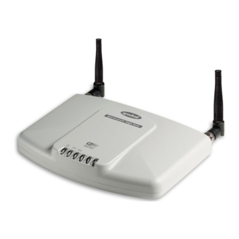
The access point uses two dipole antennas to provide diversity, improved
performance and increased signal strength over single antenna applications.
Antenna coverage resembles lighting in that an area lit from far away might
not be bright enough. An area lit sharply minimizes coverage and creates
dark areas where no light exists. Uniform access point placement provides
even, efficient coverage.
Position the access point and antenna using the following guidelines:
• Install the access point as high a practical
• Orient the access point vertically for best reception
• Point the antenna downward if attaching the access point to the ceiling.
AP-41X1-1050 HR
Access Point
Quick Reference Guide
www.symbol.com
Copyright
Copyright © 2000 by Symbol Technologies, Inc. All rights reserved.
No part of this publication may be modified or adapted in any way, for any purposes without permission in writing from
Symbol Technologies, Inc. (Symbol). The material in this manual is subject to change without notice.
Symbol reserves the right to make changes to any product to improve reliability, function, or design.
No license is granted, either expressly or by implication, estoppel, or otherwise under any Symbol Technologies, Inc.,
intellectual property rights. An implied license only exists for equipment, circuits, and subsystems contained in
Symbol products.
Symbol, the Symbol logo and Spectrum24 are registered trademarks of Symbol Technologies, Inc.
Other product names mentioned in this manual may be trademarks or registered trademarks of their respective companies
and are hereby acknowledged.
IBM is a registered trademark of International Business Machine Corporation.
Microsoft, Windows, and Windows NT are registered trademarks of Microsoft Corporation.
Novell and LAN Workplace are registered trademarks of Novell Inc.
Toshiba is a trademark of Toshiba Corporation.
Patents
This product is covered by one or more of the following U.S. and foreign Patents:
U.S. Patent No.
4,360,798; 4,369,361; 4,387,297; 4,460,120; 4,496,831; 4,593,186; 4,603,262; 4,607,156; 4,652,750; 4,673,805;
4,736,095; 4,758,717; 4,816,660; 4,845,350; 4,896,026; 4,897,532; 4,923,281; 4,933,538; 4,992,717; 5,015,833;
5,017,765; 5,021,641; 5,029,183; 5,047,617; 5,103,461; 5,113,445; 5,130,520; 5,140,144; 5,142,550; 5,149,950;
5,157,687; 5,168,148; 5,168,149; 5,180,904; 5,229,591; 5,230,088; 5,235,167; 5,243,655; 5,247,162; 5,250,791;
5,250,792; 5,262,627; 5,262,628; 5,266,787; 5,278,398; 5,280,162; 5,280,163; 5,280,164; 5,280,498; 5,304,786;
5,304,788; 5,306,900; 5,321,246; 5,324,924; 5,337,361; 5,367,151; 5,373,148; 5,378,882; 5,396,053; 5,396,055;
5,399,846; 5,408,081; 5,410,139; 5,410,140; 5,412,198; 5,418,812; 5,420,411; 5,436,440; 5,444,231; 5,449,891;
5,449,893; 5,468,949; 5,471,042; 5,478,998; 5,479,000; 5,479,002; 5,479,441; 5,504,322; 5,519,577; 5,528,621;
5,532,469; 5,543,610; 5,545,889; 5,552,592; 5,578,810; 5,581,070; 5,589,679; 5,589,680; 5,608,202; 5,612,531;
5,619,028; 5,664,229; 5,668,803; 5,675,139; 5,693,929; 5,698,835; 5,705,800; 5,714,746; 5,723,851; 5,734,152;
5,734,153; 5,745,794; 5,754,587; 5,762,516; 5,763,863; 5,767,500; 5,789,728; 5,808,287; 5,811,785; 5,811,787;
5,815,811; 5,821,519; 5,821,520; 5,823,812; 5,828,050; 5,850,078; 5,861,615; 5,874,720; 5,875,415; 5,900,617;
5,902,989; 5,907,146; 5,912,450; 5,914,478; 5,917,173; 5,920,059; 5,923,025; 5,929,420; 5,945,658; 5,945,659;
5,946,194; 5,959,285; D305,885; D341,584; D344,501; D359,483; D362,453; D363,700; D363,918; D370,478;
D383,124; D391,250; D405,077; D406,581; D414,171; D414,172
Invention No. 55,358; 62,539; 69,060; 69,187 (Taiwan); No. 1,601,796; 1,907,875; 1,955,269 (Japan);
European Patent 367,299; 414,281; 367,300; 367,298; UK 2,072,832; France 81/03938; Italy 1,138,713
Symbol Technologies, Inc.
One Symbol Place
Holtsville, NY
11742-1300
70-20846-01
Revision B
