SYMEO LPR-1DHP-291 Operator's manual

SYMEO LOCAL POSITIONING RADAR
Product: LPR®-1DHP-291
Product Documentation

SYMEO Local Positioning Radar System
LPR®-1DHP-291 –Product Documentation
Content
Copyright © Symeo GmbH 2022 Page 2 of 37
DOC.EDO.000519.0001.EN_LPR-1DHP-291_Product-Documentation.docx
Content
CONTENT................................................................................................................................2
1SAFETY NOTES ..........................................................................................................5
2THE LPR®-1DHP-291...................................................................................................8
3RADAR BASICS ..........................................................................................................9
3.1 Radar Distance Measurement Principle ...................................................................9
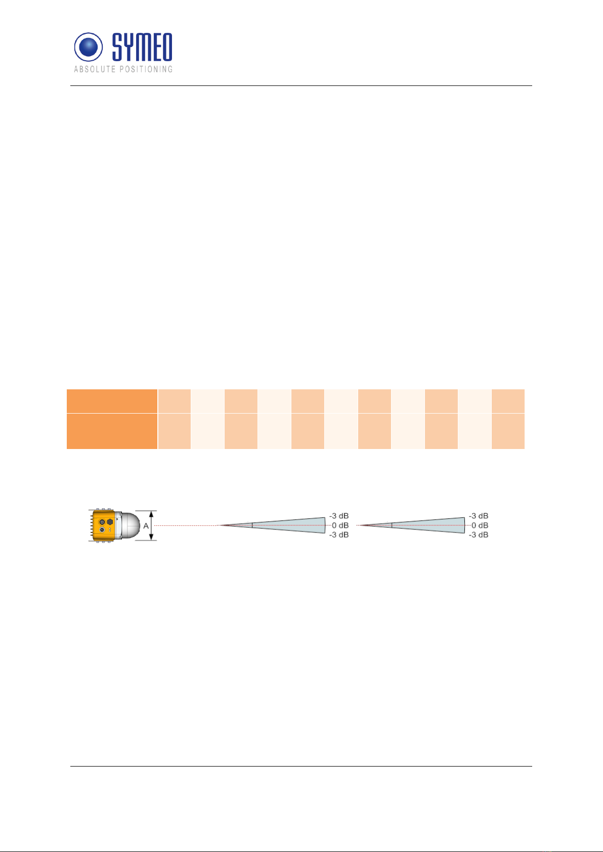
3.2 Radar Beam and Field of View (FoV)........................................................................9
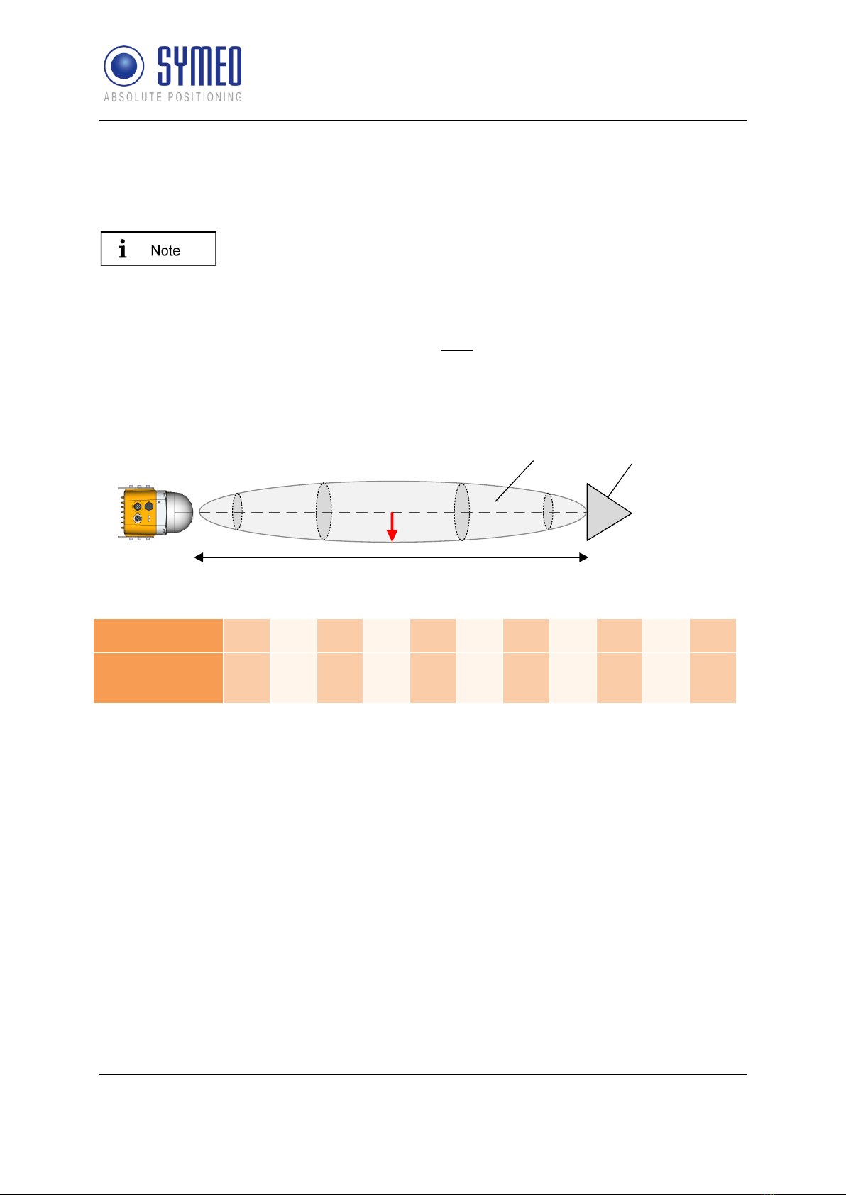
3.3 Fresnel Zone .............................................................................................................10
3.4 Radar Modes.............................................................................................................10
3.4.1 Primary Radar Mode...................................................................................................10
3.4.2Secondary Radar Mode..............................................................................................11
3.4.3 Diversity Radar Mode.................................................................................................12
3.5 Bandwidth Modes.....................................................................................................13
3.6 Accuracy....................................................................................................................13
3.7 Range.........................................................................................................................14
4COMPONENTS..........................................................................................................15
4.1 Device Overview.......................................................................................................15
4.2 LED Display...............................................................................................................18
4.3 Connectors................................................................................................................19
4.3.1 Power Supply..............................................................................................................19
4.3.2 Ethernet M12 (TCP/IP or Profinet)..............................................................................20
4.4 Mounting Brackets ...................................................................................................22
4.4.1 Mounting Bracket –MTM102513................................................................................22
4.4.2 Diversity Mounting Bracket –MTM102467.................................................................23
4.4.3 Protective cover –MTM102512..................................................................................23
4.5 Corner Reflectors .....................................................................................................24
4.5.1 Corner Reflector 500 mm –MTE000958....................................................................24
4.5.2 Corner Reflector 250 mm –MTE001011....................................................................24
4.5.3 Adjustable mounting device tube/wall –MTM000169 ................................................24
5MOUNTING................................................................................................................25

SYMEO Local Positioning Radar System
LPR®-1DHP-291 –Product Documentation
Content
Copyright © Symeo GmbH 2022 Page 3 of 37
DOC.EDO.000519.0001.EN_LPR-1DHP-291_Product-Documentation.docx
5.1 General Mounting Instructions................................................................................25
5.2 Mounting for Primary Radar Mode..........................................................................25
5.3 Mounting for Secondary Radar Mode.....................................................................26
5.4 Mounting for Diversity Radar Mode........................................................................27
6QUICK SETUP ...........................................................................................................29
6.1 Initial Setup ...............................................................................................................29
6.2 Quick Setup for Primary Radar Mode.....................................................................29
6.3 Quick Setup for Secondary Radar Mode................................................................30
6.4 Quick Setup for Diversity Radar Mode...................................................................30
7THE CUSTOMER PROTOCOL..................................................................................33
7.1 General Description..................................................................................................33
7.1.1 Structure of a Data Type.............................................................................................33
7.1.2 CRC............................................................................................................................33
7.2 Data Types.................................................................................................................34
7.2.1 Type 0x16 –Distance Data ........................................................................................34
8TECHNICAL DATA....................................................................................................37

SYMEO Local Positioning Radar System
LPR®-1DHP-291 –Product Documentation
Content
Copyright © Symeo GmbH 2022 Page 4 of 37
DOC.EDO.000519.0001.EN_LPR-1DHP-291_Product-Documentation.docx
The documentation for the LPR®-1DHP-291 Local Positioning Radar System is published by:
SYMEO GmbH
Prof.-Messerschmitt-Str. 3
D-85579 Neubiberg
www.symeo.com
If you have any questions or suggestions, please contact:
Email: [email protected]
phone: +49 89 660 7796 0
Copyright
©
Symeo GmbH
HISTORY
Version
Date
Description
0001
12.08.2022
Release for FCC/RED
SYMBOLS USED
The following symbols are used throughout the documentation:
This symbol appears before instructions that must be followed at all times.
Failure to comply with these instructions will result in personnel injury.
This symbol appears before instructions that must be followed at all times.
Failure to comply with these instructions will result in damage to
equipment.
This symbol appears before information of particular importance.
All rights reserved, particularly those relating to the translation, reprinting, and reproduction
by photocopying or similar processes of all or part of the documentation and for purposes of
the award of patents or submission of utility models.
Delivery options and technical changes reserved.
Wherever the term LPR®-1DHP-291 is used during this documentation, all products included
in the LPR®-1DHP-291 are addressed.

SYMEO Local Positioning Radar System
LPR®-1DHP-291 –Product Documentation
Safety Notes
Copyright © Symeo GmbH 2022 Page 5 of 37
DOC.EDO.000519.0001.EN_LPR-1DHP-291_Product-Documentation.docx
1 Safety Notes
General
The LPR®-1DHP-291 is a radar distance measurement sensor that may be used to measure
distances between a radar unit and a reflector or between two radar units.
LPR®-1DHP-291 radars are purely tracking and assistance systems.
They do not feature a functional safety level, e.g., Safety Integrity Level
(SIL) or Performance Level (PL), as specified in functional safety
standards (e.g., IEC 61508, EN ISO 13849, EN 62061).
Do not expose the radar to flames or heat above the specified
temperature range.
Read the documentation before operation of the radar and follow the
included safety notes.
Take note of the safety and operating instructions of the system in
which you want to install the device.
Follow national safety norms and regulations.
Installation
Installation must be carried out by qualified and trained technicians.
When the system is mounted on tubes, measures to prevent slippage of
the system must be taken.
Only screwed connections with safety against loosening may be used
for mounting the radar.
Adhere to the specified tightening torques for all screws and connectors.
Screwed connections, mounting structures and the device itself must be
examined at regular intervals, with respect to external damage and
loosened connections especially if the radar is mounted exposed or is
exposed to high stress.
Repairs and Modifications
Repairs or modifications may only be performed by the manufacturer.
Opening of the device is prohibited.
Any change or modification not expressly approved by the party
responsible for compliance could void the user’s authority to operate the
equipment.
The warranty shall be voided if defects are caused to the device by
installing or exchanging system extensions.
Transport and Storage
Do not drop the device and do not expose it to strong vibrations.

SYMEO Local Positioning Radar System
LPR®-1DHP-291 –Product Documentation
Safety Notes
Copyright © Symeo GmbH 2022 Page 6 of 37
DOC.EDO.000519.0001.EN_LPR-1DHP-291_Product-Documentation.docx
Power Supply
While installing or using it in open-air, transient overvoltage cannot be
excluded. Overvoltage protection is to be used for low voltage in
accordance with DIN EN 61643-21 and IEC 61643-21.
While connecting the plug and sockets, please observe the
correspondent chapter in this document "Connectors" and adhere to the
specified tightening torques.
Do not use damaged cables (damaged insulation, bare wires). A
defective cable may cause a fire hazard.
Be careful that the device can be damaged by reverse polarity despite
implementation of polarity reversal protection.
Setup and Operation
Protect the contacts of all the device's sockets and plugs from static
electricity.
Proper operation (in accordance with IEC60950/EN60950) of the device
is only assured if the housing and integral covers for mounting slots are
fully installed (electric shock, cooling, fire protection, noise suppression).
In case of intense, direct solar radiation or other radiant heat, it may be
necessary to provide a sun or heat shield.
Be aware, that misuse, modification, or damage of the sensor can lead
to erroneous distance measurements.
After mounting and commissioning, compare the actual distance to the
distance measured by the radar sensor with respect to your needed
accuracy. This step must be repeated after major changes to your
measurement setup.
System Extensions and Accessories
For LAN cabling, the requirements in accordance with EN 50173 and
EN 50174-1/2 apply. Use of either a Category 5 shielded cable for
10/100 Ethernet or Category 5e shielded cable for gigabit Ethernet is a
minimum requirement. The specifications of standard ISO/IEC 11801
must be complied with.
General Requirements for Compliance of Radio Apparatus
The operation of this device requires compliance with regional radio
regulations.
This device complies with Part 15 of the FCC Rules and with Industry
Canada license-exempt RSS standard(s). Operation is subject to the
following two conditions: (1) this device may not cause harmful
interference, and (2) this device must accept any interference received,
including interference that may cause undesired operation.
Le présent appareil est conforme aux CNR d'Industrie Canada
applicables aux appareils radio exempts de licence. L'exploitation est

SYMEO Local Positioning Radar System
LPR®-1DHP-291 –Product Documentation
Safety Notes
Copyright © Symeo GmbH 2022 Page 7 of 37
DOC.EDO.000519.0001.EN_LPR-1DHP-291_Product-Documentation.docx
autorisée aux deux conditions suivantes: (1) l'appareil ne doit pas
produire de brouillage, et (2) l'utilisateur de l'appareil doit accepter tout
brouillage radioélectrique subi, même si le brouillage est susceptible
d'en compromettre le fonctionnement.
Exposure Requirements
To satisfy FCC exposure requirements a separation distance of 20 cm
or more should be maintained between the antenna of this device
and persons during operation.
To ensure compliance, operations at closer distances than this are not
recommended.
To satisfy ISED exposure requirements a separation distance of 20 cm
or more should be maintained between the antenna of this device
and persons during operation.
To ensure compliance, operations at closer distances than this are not
recommended.
Pour satisfaire aux exigences d'exposition ISED, une distance d-e sépa
ration de 20 cm ou plus doit être maintenue entre l'antenne de cet
appareil et les personnes pendant le fonctionnement.
Pour assurer la conformité, les opérations à plus courte distance ne
sont pas recommandées.

SYMEO Local Positioning Radar System
LPR®-1DHP-291 –Product Documentation
The LPR®-1DHP-291
Copyright © Symeo GmbH 2022 Page 8 of 37
DOC.EDO.000519.0001.EN_LPR-1DHP-291_Product-Documentation.docx
2 The LPR®-1DHP-291
The LPR®-1DHP-291 is a radar distance measurement sensor, which performs 1D distance
measurements for short, medium and long ranges with highest accuracy.
The radar sensor can be operated in three different radar modes: primary radar mode,
secondary radar mode and diversity radar mode. Table 2.1 shows the radar modes.
LPR®-1DHP-291
Primary Radar Mode
X
Secondary Radar Mode
X
Diversity Radar Mode
X
Table 2.1: Supported radar modes for LPR®-1DHP-291 product types
Typical applications of the LPR®-1DHP-291 are:
Positioning of cranes, crane trolleys, hoists and other railbound transport systems
Process automation, monitoring and control
Collision avoidance
Radar barriers
All LPR®-1DHP-291 product types can be configured with the help of a
Web User Interface (WebUI).

SYMEO Local Positioning Radar System
LPR®-1DHP-291 –Product Documentation
Radar Basics
Copyright © Symeo GmbH 2022 Page 9 of 37
DOC.EDO.000519.0001.EN_LPR-1DHP-291_Product-Documentation.docx
3 Radar Basics
3.1 Radar Distance Measurement Principle
The LPR®-1DHP-291 radar distance sensors use electromagnetic waves to measure the
distance and speed between two radars (secondary radar mode) or a single radar and a
reflector (primary radar mode).
The underlying measuring principle is based on the Round-Trip Time-Of-Flight (RTOF)
measurement between a transmitted radar signal and a received signal. The radar estimates
the time τthe radar signal needs to travel the unknown distance dfrom one radar to the other
(or to a reflector) and back.The distance is then calculated with the formula
𝑑 = 0.5 𝜏 𝑐
where cis the speed of light.
3.2 Radar Beam and Field of View (FoV)
The LPR®-1DHP-291 emits a high frequency electromagnetic radio signal with its integrated
antenna. The EM-wave is focused by a dielectric lens and creates a radar beam with an FoV
(half power beam width, HPBW) of +/-2,5°.
Table 3.1: Radar beam 3 dB diameter vs. distance
LPR®-1DHP-220-R
Integrated antenna
verticalhorizontal
5° 5°
Figure 3.1: Radar beam and field of view
Distance d in m
1
3
10
30
50
70
100
200
300
400
600
Radar beam 3dB
diameter in m
0.1
0.3
0.9
2.6
4.4
6.1
8.7
17.5
26.2
34.9
52.4

SYMEO Local Positioning Radar System
LPR®-1DHP-291 –Product Documentation
Radar Basics
Copyright © Symeo GmbH 2022 Page 10 of 37
DOC.EDO.000519.0001.EN_LPR-1DHP-291_Product-Documentation.docx
3.3 Fresnel Zone
The area for radio transmission between two antennas is called Fresnel zone. The main part
of energy is concentrated in the first Fresnel zone.
The Fresnel zone must be free of any obstacles to ensure that the
signal is not attenuated or interrupted.
The maximum radius of the first Fresnel zone (in the middle between two antennas) can be
calculated as follows:
𝑟 = 0.5 ∙ √𝜆 ∙ 𝑑
𝜆is the wavelength and 𝑑the distance between the two radar devices or a radar device and
a reflective target. For a frequency of 61 GHz the wavelength 𝜆equals to 0.005 m. The
maximum radius for different distances is given in Table 3.2.
Corner reflector
r
Fresnel zone
Figure 3.2: Fresnel zone
Table 3.2: Fresnel zone radius vs. distance
3.4 Radar Modes
3.4.1 Primary Radar Mode
In primary radar mode, a single radar measures the distance and speed to a reflective object
/ target, typically a metal corner reflector.
Figure 3.3 shows the typical setup of an LPR®-1DHP-291 radar and a corner reflector for a
primary radar distance measurement.
Distance d in m
10
20
30
40
50
70
100
200
300
400
600
Fresnel zone
Radius r in m
0.11
0.16
0.19
0.22
0.25
0.30
0.36
0.50
0.62
0.71
0.86

SYMEO Local Positioning Radar System
LPR®-1DHP-291 –Product Documentation
Radar Basics
Copyright © Symeo GmbH 2022 Page 11 of 37
DOC.EDO.000519.0001.EN_LPR-1DHP-291_Product-Documentation.docx
Figure 3.3: Primary radar mode measurement setup
3.4.2 Secondary Radar Mode
In secondary radar mode, two radars measure the distance and speed between each other.
Figure 3.4 shows the typical setup of two LPR®-1DHP-291 radars for a secondary radar
range measurement.

SYMEO Local Positioning Radar System
LPR®-1DHP-291 –Product Documentation
Radar Basics
Copyright © Symeo GmbH 2022 Page 12 of 37
DOC.EDO.000519.0001.EN_LPR-1DHP-291_Product-Documentation.docx
Figure 3.4: Secondary radar mode measurement setup
3.4.3 Diversity Radar Mode
In diversity radar mode, four radar units are grouped into two pairs, which are mounted in a
way that two secondary radar measurements are performed side by side separated by a
defined distance.
Figure 3.5 shows the typical setup of four LPR®-1DHP-291 radars for a diversity radar range
measurement.
Figure 3.5: Diversity radar mode measurement setup

SYMEO Local Positioning Radar System
LPR®-1DHP-291 –Product Documentation
Radar Basics
Copyright © Symeo GmbH 2022 Page 13 of 37
DOC.EDO.000519.0001.EN_LPR-1DHP-291_Product-Documentation.docx
3.5 Bandwidth Modes
The LPR®-1DHP-291 operates in the 57 - 64 GHz band. Depending on your used region and
regulatory authority setting, a limited number of bandwidth modes are available for selection
in the WebUI.
The selected bandwidth modes have impact on the accuracy, resolution and range of the
radar.
Within a single bandwidth mode, multiple sync channels are available. For each channel
block, the effective bandwidth of a sync channel slightly reduces with increasing sync
channel number.
3.6 Accuracy
To maximize the accuracy of an LPR®-1DHP-291 measurement setup, different error
sources which influence the accuracy need to be taken into account:
Mounting position
oAdhere to the mounting instructions (see chapter 5) to minimize systematic errors
(e.g., horizontal or vertical offset and alignment)
Reflective surfaces and objects
oUnwanted reflections of the radar signal, e.g., from crane tracks or walls, can cause
distance errors which vary with the measured distance. Ensure the recommended
clearance to surfaces and objects described in chapter 5.1 or use diversity radar
mode to minimize errors caused by reflections
Measurement noise
oMeasurement noise caused by the radar itself is the lower limit to the overall
accuracy. The noise will decrease with increasing bandwidth. For primary radar mode
the influence of noise will increase with range and decrease with target radar cross
section (dependent on target size, shape and material). In secondary radar mode
noise is mostly constant within the specified range and will increase for longer ranges.
A reduction of the transmit power can lead to a reduction of the measurement noise
at the expense of maximum range
Temperature drift
oChanges in device and air temperature can lead to measurement offsets. These
errors vary slowly with time and can be countered by ensuring constant
environmental conditions, running a warmup phase of 30 minutes before operation or
by using a calibration reference
Weather and environmental conditions
oUnder severe weather and environmental conditions such as very heavy rain or snow
fall and layers of ice, snow, dust or other absorbing and reflecting material being
attached to the lens the measurement may be prone to distance offsets of up to +/-
10mm.

SYMEO Local Positioning Radar System
LPR®-1DHP-291 –Product Documentation
Radar Basics
Copyright © Symeo GmbH 2022 Page 14 of 37
DOC.EDO.000519.0001.EN_LPR-1DHP-291_Product-Documentation.docx
3.7 Range
To maximize the range of an LPR®-1DHP-291 measurement setup the following aspects
must be taken into account:
Mounting position
oAdhere to the mounting instructions (see chapter 5). Ensure minimum alignment error
and vertical / horizontal offset and equal orientation (for secondary and diversity radar
mode)
Fresnel zone
oEnsure the Fresnel zone is free of absorbing or reflecting objects
Reflective surfaces and objects
oReflections of the radar signal, e.g., from walls, can lead to a reduction of the
received signal strength and hence maximum range. Ensure the recommended
clearance to surfaces and objects described in chapter 5.1 or use diversity radar
mode to counter the effects caused by reflections
Target RCS (only primary radar mode)
oIn primary radar mode the maximum range depends on the target RCS (radar cross
section) which is a function of target size, material, and shape. If a high range is
required use targets with a high RCS (e.g., the corner reflector MTE000958)
Weather and environmental conditions
oUnder severe weather and environmental conditions as stated in chapter 3.6 the
maximum operating range may be decreased.
The measurement range given in the technical specification in chapter 8 and the datasheets
is the typical range in which operation is possible under most conditions. The sensor may be
operated at higher or lower ranges if circumstances permit.

SYMEO Local Positioning Radar System
LPR®-1DHP-291 –Product Documentation
Components
Copyright © Symeo GmbH 2022 Page 15 of 37
DOC.EDO.000519.0001.EN_LPR-1DHP-291_Product-Documentation.docx
4 Components
4.1 Device Overview
The LPR®-1DHP-291 consists of the following parts (see Figure 4.1 and Figure 4.2):
Dielectric lens (A1)
ofocuses the radar beam
Metal gland (A2)
ofixes the lens to the housing with four screws
oseals the device against water and dirt
oholds the inner parts of the device in place
Housing (A3)
oprovides LEDs (B1) and a pressure equalization membrane (B2)
oprovides the M12 power supply connector (C1) and the M12 Ethernet connector (C2)
oprovides 2 x 3 M6 screwing holes (B3) for mounting in the mounting bracket
oprovides an adjustment guide for usage with a laser level for exact radar beam
alignment (B4)
oensures IP65 protection class and heat dissipation
The housing must not be opened.

SYMEO Local Positioning Radar System
LPR®-1DHP-291 –Product Documentation
Components
Copyright © Symeo GmbH 2022 Page 16 of 37
DOC.EDO.000519.0001.EN_LPR-1DHP-291_Product-Documentation.docx
Figure 4.1: Front view of the LPR®-1DHP-291
A1
A2
A3
B1
B2
B3
B3
C1
C2

SYMEO Local Positioning Radar System
LPR®-1DHP-291 –Product Documentation
Components
Copyright © Symeo GmbH 2022 Page 17 of 37
DOC.EDO.000519.0001.EN_LPR-1DHP-291_Product-Documentation.docx
Figure 4.2: Side view of the LPR®-1DHP-291
B3
B4

SYMEO Local Positioning Radar System
LPR®-1DHP-291 –Product Documentation
Components
Copyright © Symeo GmbH 2022 Page 18 of 37
DOC.EDO.000519.0001.EN_LPR-1DHP-291_Product-Documentation.docx
Figure 4.3: LPR®-1DHP-291 housing dimensions
4.2 LED Display
The LEDs (Status LED on the left and Ethernet LED on the right) indicate the different states
of the device (see Table 4.1).
LED Indication
Status of the Device
Status LED lights up BLUE
Device is booting up
Status LED lights up RED
Invalid measurement
Status LED lights up GREEN
Valid measurement
Status LED flashes BLUE
Firmware update in progress
Ethernet LED lights up WHITE
Ethernet interface established
Ethernet LED flashes WHITE
Ethernet interface transmits data
Table 4.1: LED Display

SYMEO Local Positioning Radar System
LPR®-1DHP-291 –Product Documentation
Components
Copyright © Symeo GmbH 2022 Page 19 of 37
DOC.EDO.000519.0001.EN_LPR-1DHP-291_Product-Documentation.docx
4.3 Connectors
The housing of the LPR®-1DHP-291 provides the following M12 connectors (see Figure 4.1
and Figure 4.2):
Power supply input (C1)
Ethernet connector (C2) for network connection
The necessary connectors for manufacturing cables that fit your installation and cable length
are available from Symeo and are described in the following chapters.
We recommend the following tool set from PHOENIX CONTACT for proper M12 torque
moment screwing:
•Torque head - SAC BIT M12-D15 –1208432
•Grip - TSD 04 SAC –1208429
4.3.1 Power Supply
The LPR®-1DHP-291 is powered via a 4-pin M12-Connector.
Plugs
Recommended connector:
•SACC-M12FST-4CON-PG 9-M - 1418052
oCable diameter: 6 - 8 mm
Tightening torque: 0.4 Nm
oSymeo order number: MTE101761
The connector is also part of the following M12 connector set:
•M12 connector set (Ethernet + Power supply)
oSymeo order number: MTE102366
Figure 4.4: M12 power supply connector

SYMEO Local Positioning Radar System
LPR®-1DHP-291 –Product Documentation
Components
Copyright © Symeo GmbH 2022 Page 20 of 37
DOC.EDO.000519.0001.EN_LPR-1DHP-291_Product-Documentation.docx
Pin Assignment
Power Supply 11 V DC –36 V DC
M12 Connector
VDC+
Pin 1
VDC+
Pin 2 (bridged to Pin 1)
VDC-
Pin 3
VDC-
Pin 4 (bridged to Pin 3)
Table 4.2: Pin assignment power supply
4.3.2 Ethernet M12 (TCP/IP or Profinet)
The LPR®-1DHP-291 can be connected to a TCP/IP or a Profinet bus system (Production
Code "n" required) via an M12 Ethernet Connector.
A Profinet interface application note is available for download in the
Symeo Partner Login area.
Plugs
Recommended connector:
•SACC-M12MSD-4CON-PG 7-SH –1521258
oCable diameter: 4 –6 mm (PG7)
Tightening torque: 0.4 Nm
oSymeo order number: MTE101768
The connector is also part of the following M12 connector set:
•M12 connector set (Ethernet + Power supply)
oSymeo order number: MTE102366
Table of contents
Other SYMEO Accessories manuals