565E
1
IntroductionChapter 1
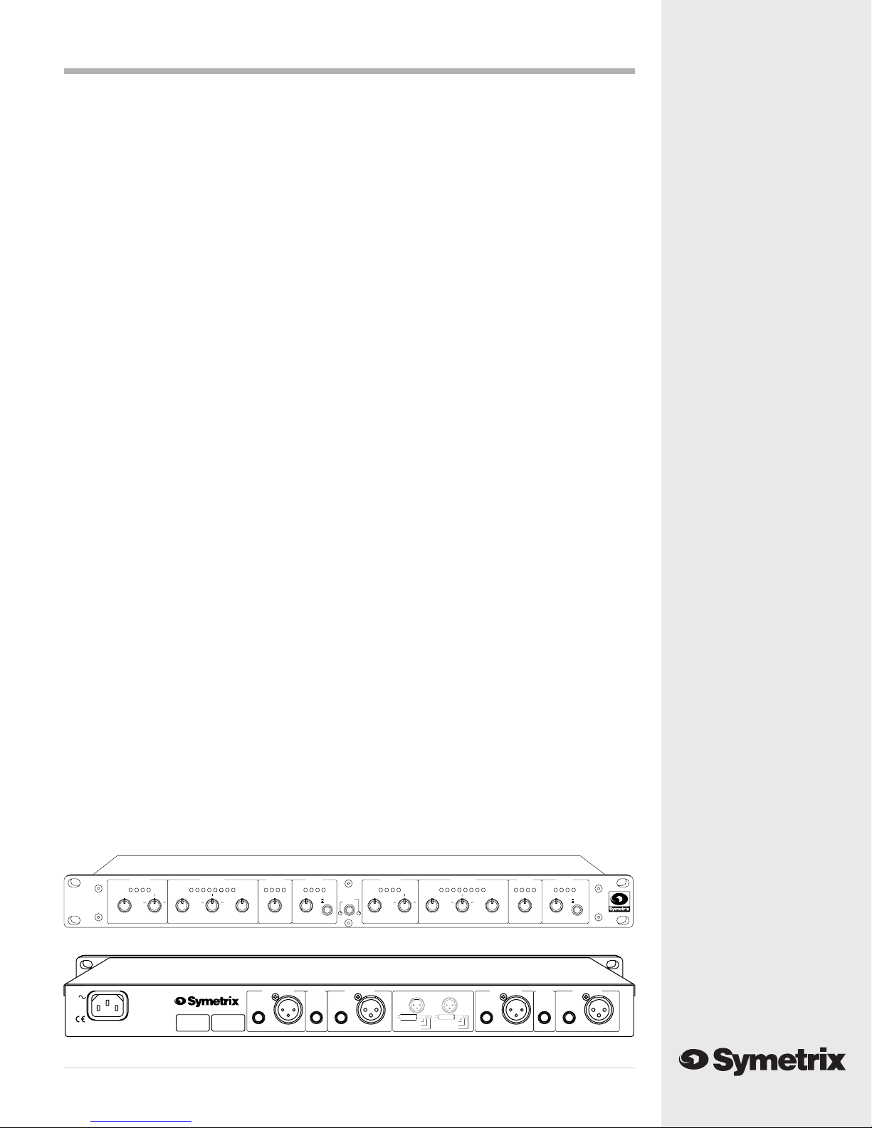
Front panel
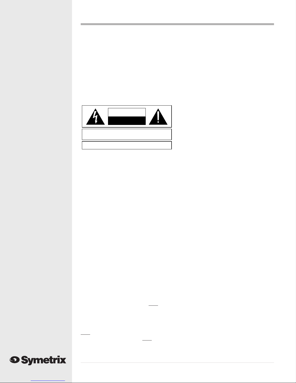
Rear panel
CH2 OUTPUT
-10 0dBu CLIP
-3 -20
-12 -9 -6
CH2 COMPRESSOR
-6 -4 -2-12-15 -10 -8-2-6-18 -12
CH2 EXPANDER
-25
CH2 LIMITER
0
IN
+10-10
+13
BYPASS
+20
-20
GAIN (dB)
4 +5
-362.5
-10
-12
-25-250 +5
-12
10SLOW 1FAST
RELEASE RATIO (X:1)
-40 +20
SLOW
RELEASE
BYPASS
+10
THRESHOLD (dBu)
FAST
THRESHOLD (dBu) THRESHOLD (dBu)
BYPASS
CH1 OUTPUT
-10 0dBu CLIP
CH1 LIMITER
-12 -6-9 -3 -20-4-6 -2-15 -10-12 -8-25
CH1 COMPRESSOR
CH1 EXPANDER
-18 -2-12 -6
IN
+5 0
+10-10
-3 +13
BYPASS
4-10
62.5+5
+20
-20-12 BYPASS
THRESHOLD (dBu) GAIN (dB)
10
1
RATIO (X:1)
FAST-40 +20 SLOW
RELEASE
-12
-250
565
DUAL
EXPANDER
COMPRESSOR/
LIMITER/
E
SLOW
BYPASS FAST
RELEASE
+10
THRESHOLD (dBu) THRESHOLD (dBu)
-25
STEREO LINK
STEREO
DUAL MONO
CHANNEL 1 INPUTSIDECHAIN
INPUT
KEY
CHANNEL 1 OUTPUT
BALANCED/
UNBALANCED
BALANCEDBALANCED
OUTPUTS
BALANCED
TYPICAL CONNECTIONS
3
1
SIDECHAIN
31
GROUND=PIN 1
HIGH(+)=PIN 2
LOW(-)=PIN 3
22
INPUTS
BALANCED
CHANNEL 2 INPUT
1/4"BALANCED
SIDECHAIN OUT
KEY INPUT
GROUND
BALANCED
SLEEVE=GROUND
RING=LOW(-)
TIP=HIGH(+)
SIDECHAIN
INPUT
KEY
E
DUAL COMPRESSOR/
LIMITER/EXPANDER
BALANCED/
UNBALANCED
CHANNEL 2 OUTPUT
BALANCED
UNBALANCED
BALANCED/
AC INPUT
MAXIMUM
15 WATTS
FABRIQUÉ AUX E.-U. PAR SYMETRIX INC., LYNNWOOD, WA USA.
RÉFÉREZ TOUTE RÉPARATION À UN TECHNICIEN QUALIFIÉ.
MANUFACTURED IN LYNNWOOD, WASHINGTON USA
565
UNBALANCED
BALANCED/
Congratulations on your purchase of the
Symetrix565E:aone-boxanswertoyour
dynamics processing needs. The 565E Dual
Compressor/Limiter/Expanderofferstwo
channels of simultaneous, in-line controls for
compression,limitinganddownwardexpan-
sion. In addition, the 565E employs a new
circuitrydesign,DynamicsSquared™,for
dramatically reduced distortion during gain
reduction.
Compression,limiting,anddownwardexpan-
sion clear up different but related audio
problems. Whether you work with vocal tracks,
stage monitors, radio signals, paging systems
or playback systems, it's likely that your audio
needs more than one of these solutions.
The compressor and expander sections of the
565Efeaturenewly-developedcircuitry,
DynamicsSquared™.Thisproprietarydesign
addresses a key problem: most analog com-
pressors use conventional voltage-controlled
amplifier topography, which creates added
distortion when compressing mid-band
frequencies.DynamicsSquared™resolves
this problem by using circuitry that controls
gain while reducing distortion. As a result, the
565E allows you to apply high levels of
compression and expansion with much less
distortion.
If background noise, tape hiss, or pickup hum
isaproblem, eliminate itwiththe downward
expander. The 565E uses a true downward
expander, not a so-called “soft gate”. The
565E's downward expander won’t chop off the
transients and decays like a gate would, yet it
can work just as effectively for reducing those
noises between sounds.
While the downward expander quiets un-
wanted noise, the 565E’s compressor section
allows you to apply the right amount of
compression without pumping or breathing.
The separate limiter section guards against
peaks that lead to overload problems, freeing
the compressor section for settings specific to
compression and not protection. (Trying to set
a typical compressor for both compression and
peak protection usually results in less-than-
idealsettings.)The 565E'slimiterprotects
against sharp peak signals while the compres-
sor smooths out the audio program for a silky,
pleasing finish.
The 565E's sidechain allows users to alter all
three processing sections for special applica-
tions. Inserting an equalizer at the sidechain
can make the action of the 565E's compressor/
limiter/expanderfrequency-dependent.Empha-
size or de-emphasize a particular signal range to
make the 565E respond more or less to certain
frequencies.
Regardless of what your audio challenges may
be, the 565E offers a powerful variety of
solutions. In-line compression, limiting, and
expansion produce clean, clear audio in any
situation. Innovative circuitry permits users to
choose optimal settings without paying the
price of extra distortion.
We recommend that you read this manual
cover-to-cover. You will find the answers to
most of your questions inside. However, if you
are in a hurry, go directly to Chapter 3 (Fast
Setup). It will get you started quickly. Should
you have any comments or questions, please
do not hesitate to contact us at the numbers/
addresses below. Your calls are always
welcome.
Phone: (425)7873222
Fax: (425)7873211
Website:www.symetrixaudio.com