DOC-1000598-B-4
•For outdoor installations use a proper sized conduit
and a sealed power entry connector in order for the
box to meet NEMA 4X standards.
NOTE: The Central Base Station holds a rating of IP65 for
outdoor when the door is latched, and all entry ports
(power and ethernet) are properly sealed. Failure to
properly seal entry ports and latch the door will void the
IP65 rating.
SURGE PROTECTION OPERATION
Lights will come on after 15 minutes of no communication with
the unit.
In the event of a strong surge, this unit will protect itself and
will be disconnected from AC power until the surge protection
device (SPD) is replaced. The Surge protection device must be
replaced if the facility lights remain on and there is no power to
the unit. Inside the connection compartment, if the green LED
on the SPD is off, replace with part number SPD-20HP-277S.
WARNING: THERE ARE NO SERVICEABLE
COMPONENTS INSIDE THE CENTRAL BASE
STATION, except for the Surge Protection Device
which should only be replaced by a licensed electrician.
The Surge Protection Device replacement part number
is SPD-20HP-277S.
OPERATION INSTRUCTIONS FOR PUSH BUTTONS
The default behavior for the 5 buttons are as follows:
1. 100% Light Level (Zone All)
2. 75% Light Level (Zone All)
3. 50% Light Level (Zone All)
4. 25% Light Level (Zone All)
5. Off (Zone All)
NOTE: To program the button for a different behavior please
contact your commissioning agent, refer to any training
material you received, or open a support ticket at-
https://support.synapsewireless.com/
INSTRUCTIONS FOR INSTALLING OUTDOOR
ANTENNA KIT - OPTIONAL
The Central Base Station includes an external connector on the
bottom of the unit for use with the Synapse Outdoor Antenna
Kit. This external antenna and cable help ensure that the
SimplySnap gateway signal is amplified and propagated to
other devices. This is important on large sites or sites with
large physical obstructions between the SimplySnap gateway
and lighting controllers.
Note: For more Details on outdoor antenna installation
instructions please see the Outdoor Antenna Install Guide
https://help.synapsewireless.com/Lighting/Assets/Hardware_Gui
des/Outdoor Antenna Install Guide.pdf
If you are using an outdoor antenna kit, follow the instructions
below to prepare the Central Base Station for connection using
the external connector on the bottom of the unit.
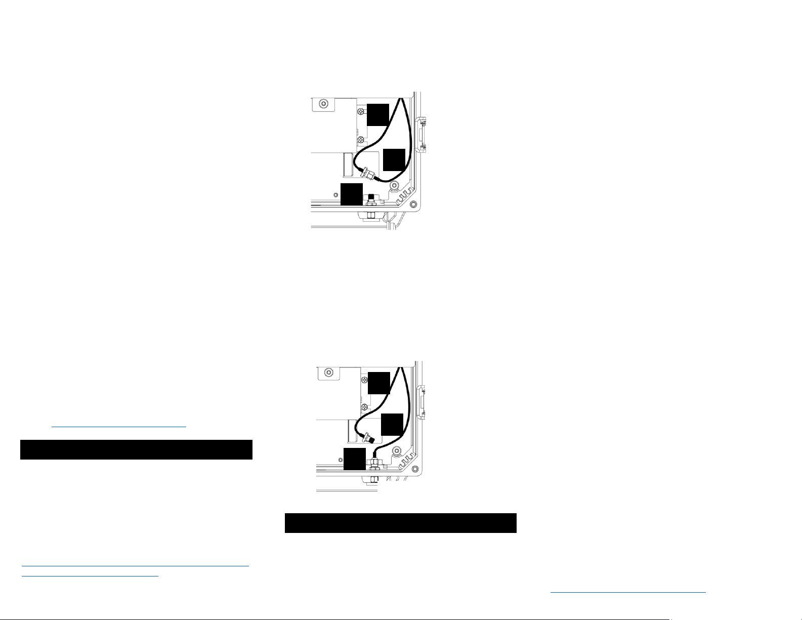
1. With the lower cover of the wiring compartment removed,
find the cable A and B and connector C as shown below in
the bottom right of the unit. (Figure 2).
2. Unscrew the connectors on cable A and B to disconnect
cable A from cable B.
3. Screw on and hand tighten the connector on cable B to
connector C as shown below. (Figure 3)
4. Tighten a ¼ turn with a pair of needle nose pliers. Do
not over tighten or the RF pin in the bulkhead will crack,
creating poor RF link quality.
5. Place the lower cover back into position and tighten the
two screws. (Figure 1)
6. Connect the external cable and antenna according to
the install guide included with the Outdoor Antenna Kit.
REGULATORY INFORMATION AND
CERTIFICATIONS
RF Exposure Statement: This equipment complies
with FCC radiation exposure limits set forth for an
uncontrolled environment. This equipment should be
installed and operated with minimum distance of 20cm
between the radiator and your body. This transmitter
must not be co-located or operating in conjunction with
any other antenna or transmitter.
Industry Canada (IC) certifications: This digital
apparatus does not exceed the Class B limits for radio
noise emissions from digital apparatus set out in the
Radio Interference Regulations of the Canadian
Department of Communications.
Le present appareil numerique n’emet pas de bruits
radioelectriques depassant les limites applicable aux
appareils numeriques de la class B prescrites dans le
Reglement sur le brouillage radioelectrique edicte par le
ministere des Communications du Canada.
FCC certifications and regulatory information
(USA only)
FCC Part 15 Class B: This device complies with part
15 of the FCC rules. Operation is subject to the
following two conditions: (1) These devices may not
cause harmful interference, and (2) These devices must
accept any interference received, including interference
that may cause harmful operation.
RADIO FREQUENCY INTERFERENCE (RFI) (FCC
15.105): This equipment has been tested and found to
comply with the limits for a Class B digital device,
pursuant to Part 15 of the FCC rules. These limits are
designed to provide reasonable protection against
harmful interference in a residential installation. This
equipment generates, uses, and can radiate radio
frequency energy and, if not installed and used in
accordance with the instructions, may cause harmful
interference to radio communications. However, there
is no guarantee that interference will not occur in a
particular installation. If this equipment does cause
harmful interference to radio or television reception,
which can be determined by turning the equipment off
and on, the user is encouraged to try to correct the
interference by one or more of the following measures:
(1) Re-orient or relocate the receiving antenna; (2)
Increase the separation between the equipment and
the receiver; (3) Connect the equipment into an outlet
on a circuit different from that to which the receiver is
connected; (4) Consult the dealer or an experienced
radio/TV technician for help.
CERTIFICATIONS
Model : CBSSW-450-002
Contains FCC ID : U9O-SM220
Contains IC : 7084A-SM220
UL File No : E346690
ROHS :3:2011/65/EU(2015/863)
For Support-
Please contact your commissioning agent or installer,
or open a support ticket at-
https://support.synapsewireless.com/