Synovatron cvgt MM User manual

cvgt MM User Manual
1
Copyright © 2014 Synovatron Limited. All rights reserved. (Rev 0 Febr ary 2014)

cvgt MM User Manual
2
Copyright © 2014 Synovatron Limited. All rights reserved. (Rev 0 Febr ary 2014)
Introduction
Thank yo for p rchasing the Synovatron cvgt MM B chla™ Translator
Mod leMod le™. This man al explains what the cvgt MM is and how it works.
The cvgt MM is a Mod leMod le format synthesizer mod le and is compatible
with the Eardrill™ Mod leMod le Model 041 Frame. The cvgt MM fits in any
one of the fo r positions within the Model 041 frame.
The cvgt MM (Control Voltage Gate Trigger Mod le Mod le) is a CV and
Gate/Trigger interface that provides a means of exchanging CV and timing
p lse control signals between a B chla 200e Series synthesizer and another
1V/octave synthesizer. The cvgt MM is available in fo r basic variants: the
3.5mm jack socketed E rorack and banana socketed Serge™, B gBrand™ and
Fenix™ variants.
Caution
Personal and equipment safety
Please ens re yo se the cvgt MM in accordance with these instr ctions
especially taking great care to connect the power cable to the Model 041
Frame. The power cable is keyed b t always do ble check!
Only fit and remove mod les with the rack power off and
disconnected from the mains electricity supply for yo r own safety.
Refer to the connection section for power cable connection instructions.
Synovatron Electronic Music cannot be held responsible for any damage or
harm caused through incorrect or unsafe use of this module. If in doubt, stop
and check. If you are still unsure of what to do then please contact
Synovatron for advice before proceeding.

cvgt MM User Manual
3
Copyright © 2014 Synovatron Limited. All rights reserved. (Rev 0 Febr ary 2014)
Eurorack variant: Switchcraft™ Tini-jax™ plu and 3.5mm
jack socket incompatibility
The Eurorack variant cvgt MM, shown above, has 3.5mm jack sockets for
E rorack connections. Please be warned that connecting a Switchcraft Tini-
jax plug to a 3.5mm jack socket will damage the 3.5mm jack contacts as the
Tini-jax pl g has a larger diameter. Synovatron Electronic M sic cannot be held
responsible for any contact damage ca sed thro gh incorrect connection to
this mod le and this will invalidate yo r warranty.

cvgt MM User Manual
4
Copyright © 2014 Synovatron Limited. All rights reserved. (Rev 0 Febr ary 2014)
cvgt MM Description
The cvgt MM has fo r channels; two for CV signal translation and two for
timing signal translation. These are described as follows:-
1.2V/Octave to 1V/Octave CV Translation Channel
This is a precision b ffered DC co pled atten ator with an atten ation factor
of 0.8333. It is designed to translate B chla CV inp t signals, which have a
1.2V/octave scaling, to an o tp t compatible with synthesizers with a
1V/octave scaling.
1.2v/octave in A B chla compatible 1.2V/octave CV
inp t black banana socket. The nominal inp t range is
0V to +10V.
1v/octave out A 1V/octave compatible CV o tp t.
The o tp t range is 0V to +8.333V.
Variant Info: A 3.5mm jack socket (Eurorack
compatible) is shown but depending on the variant
purchased could be a banana socket (colour coded
either blue for Serge and enix or red for BugBrand
outputs).
There is a front panel accessible 10-t rn trim pot that can be adj sted with a
small screwdriver. This is factory set to an atten ation of 0.8333 exactly. It is
for very fine t ning only and can only adj st over a small range.
External CV to Buchla CV Translation Channel
This is a precision DC co pled amplifier designed to translate nipolar and
bipolar inp t signals from external synthesizers into the B chla 0V to +10V
inp t range.
These inp ts co ld, for example, be from a bipolar LFO (±5V), a nipolar ADSR
(0-8V), a nipolar q antizer (0-5V) etc. The scale and offset switches, in
conj nction with the –v LED, are sed to keep the o tp t to the B chla within
the 0V to +10V range.

cvgt MM User Manual
5
Copyright © 2014 Synovatron Limited. All rights reserved. (Rev 0 Febr ary 2014)
ext cv in The CV inp t from an external
synthesizer.
Variant Info: A 3.5mm jack socket (Eurorack
compatible) is shown but depending on the
variant purchased could be a banana socket
(colour coded either blue for Serge and
BugBrand or black for enix inputs).
CV out A B chla compatible CV o tp t bl e
banana socket. The o tp t range is 0V to +10V.
scale This switch allows the gain to be changed to match the scale factor
or voltage range of the synthesizer signal connected to ext cv in. This can be
set for 1V/octave, 1.2V/octave and 2V/octave scales; in the 1 position the
amplifier has a gain of 1 ( nity), in the 1.2 position it has a gain of 1.2 and in
the 2 position it has a gain of 2.
offset This switch provides an o tp t offset that is added to the scaled
inp t signal of either 0V (0v) or +5V (+v). In the 0v position no offset is added
so a positive going inp t signal (e.g. envelope) will keep the o tp t positive
going.
–v LED indicator lights if the o tp t signal goes negative to warn that the
signal is o tside the sef l range of 0V to +10V for the B chla synthesizer.
The simplified schematics (a) to (f) explain in simple arithmetic terms what
inp t ranges are req ired to translate to an o tp t range of 0V to +10V sing
the vario s offset and scale switch positions.
Schematics (a) to (c) show the offset switch in the 0v position for each of the
three scale positions. Schematics (d) to (f) show the offset switch in the +v
position for each of the three scale positions.
There is a front panel accessible trim pot that can be adj sted with a small
screwdriver. This is factory set to a gain of 1.200 exactly (for the 1.2 scale). It
is for very fine t ning only and can only adj st over a small range.

cvgt MM User Manual
6
Copyright © 2014 Synovatron Limited. All rights reserved. (Rev 0 Febr ary 2014)

cvgt MM User Manual
7
Copyright © 2014 Synovatron Limited. All rights reserved. (Rev 0 Febr ary 2014)
B chla P lse to Gate Trigger Translator Channel
This channel is specifically designed to convert the tri-state timing p lse o tp t
from B chla 225e and 222e synthesizer mod les into 10V gate and trigger
signals that are compatible with other formats. It will also work with any signal
that exceeds the inp t thresholds of either the gate or trigger detectors as
follows:-
pulse in An orange banana socket inp t
compatible with B chla p lse o tp ts in the
range of 0V to +15V.
gate out A 0V to 10V o tp t. The o tp t
goes high (+10V) when the pulse in voltage is
above +2.7V. This is intended to follow the
gate or s stain part of B chla 225e and 222e
mod le p lses altho gh any signal exceeding
+2.7V will ca se this o tp t to go high. Refer
to the example timing diagram below. The LED
ill minates when gate out is high.
Variant Info: A 3.5mm jack socket (Eurorack compatible) is shown but
depending on the variant purchased could be a banana socket (colour coded
either red for Serge and BugBrand or blue for enix outputs).
trig out A 0V to 10V o tp t. The o tp t goes high (+10V) when the pulse
in voltage is above +7.7V. This is intended to follow the initial trigger part of
B chla 225e and 222e mod le p lses altho gh any signal exceeding +7.7V will
ca se this o tp t to go high.
Variant Info: A 3.5mm jack socket (Eurorack compatible) is shown but
depending on the variant purchased could be a banana socket (colour coded
either red for Serge and BugBrand or blue for enix outputs).
Note that trig out does not shorten pulses it just transmits the high
level pulses at the width presented to pulse in which are all narrow
pulses on Buchla synth pulse outputs. Refer to the example timing
diagram on the next page.

cvgt MM User Manual
8
Copyright © 2014 Synovatron Limited. All rights reserved. (Rev 0 Febr ary 2014)
(a) (b) (c) (d)
The timing diagram above shows fo r example pulse in inp t waveforms and
the gate out and trig out responses. The inp t switching thresholds for the
gate and trigger level detectors are shown at +2.7V and +7.7V.
The first example (a) shows the p lse shape similar to that of a B chla 225e
and 222e mod le p lses; an initial trigger p lse followed by a s stain level
which is reflected in the gate out and trig out responses.
Examples (b), (c) and (d) show that p lses are j st passed thro gh (at +10V) to
gate out and trig out if they exceed the respective thresholds. A signal that
exceeds both thresholds will be present on both o tp ts.

cvgt MM User Manual
9
Copyright © 2014 Synovatron Limited. All rights reserved. (Rev 0 Febr ary 2014)
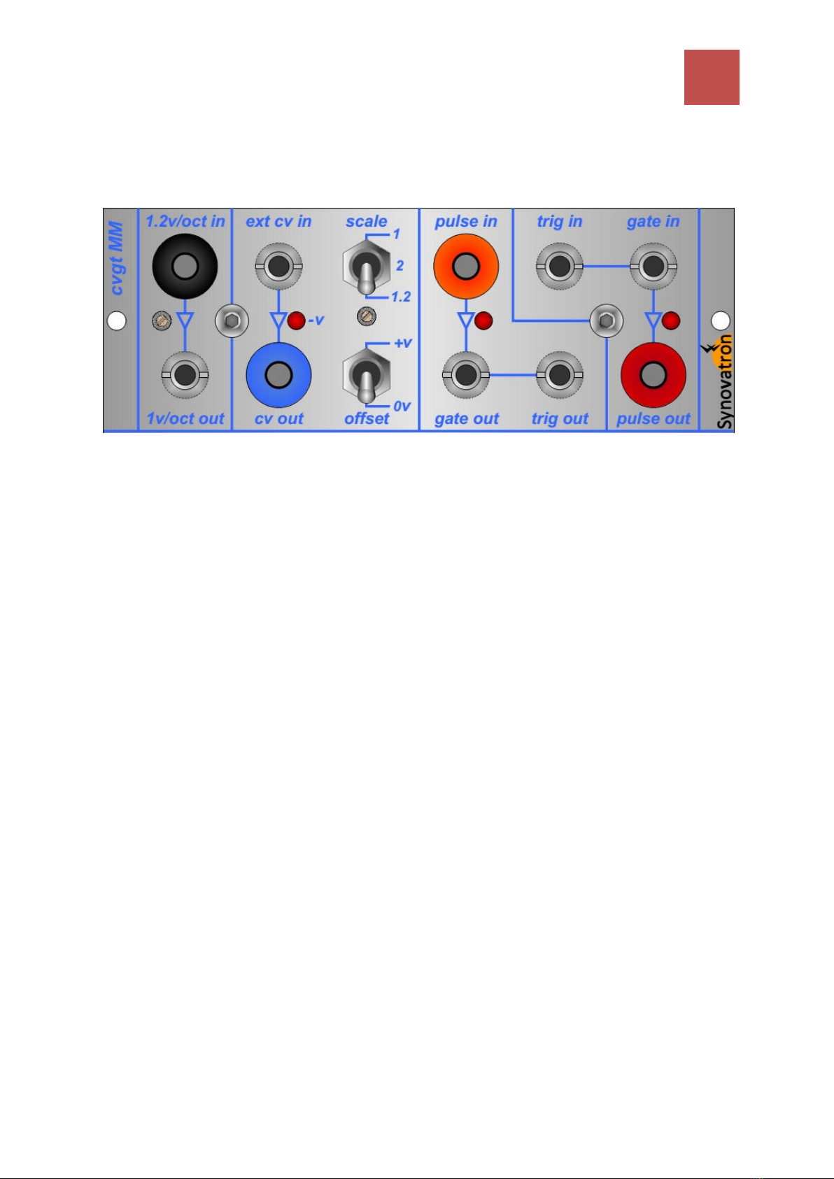
Gate Trigger to B chla P lse Translator Channel
This channel is specifically designed to convert gate and trigger signals into a
timing p lse o tp t compatible with B chla synthesizer p lse inp ts.
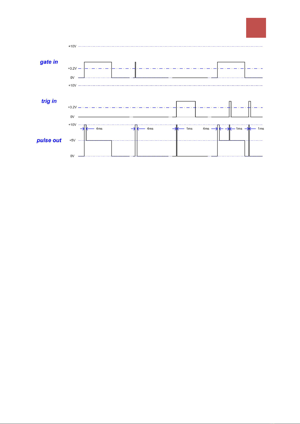
trig in An inp t that when the signal
applied exceeds the inp t threshold of
+3.2V will generate a +10V narrow p lse
(trimmer adj stable in the range 0.5ms to
5ms; factory set to 1ms) at pulse out
irrespective of the inp t p lse width.
Variant Info: A 3.5mm jack socket
(Eurorack compatible) is shown but
depending on the variant purchased could
be a banana socket (colour coded either
red for Serge, black for enix or blue for
BugBrand inputs).
gate in An inp t that when the signal applied exceeds the inp t threshold
of +3.2V will generate an o tp t at pulse out that is compatible with B chla™
225e and 222e mod le p lses i.e. it will ca se a tri-state o tp t p lse. The
gate in leading edge will generate a +10V narrow trigger p lse (also trimmer
adj stable in the range 0.5ms to 5ms; factory set to 4ms) at pulse out
irrespective of the inp t p lse width. It will also generate a +5V s staining
‘gate’ signal for the d ration of the inp t p lse if it extends beyond the narrow
trigger p lse. This can be seen in example (a) in the timing diagram on the next
page.
Variant Info: A 3.5mm jack socket (Eurorack compatible) is shown but
depending on the variant purchased could be a banana socket (colour coded
either red for Serge, black for enix or blue for BugBrand inputs).
pulse out A banana socket o tp t compatible with B chla synthesizer p lse
inp ts. It o tp ts a composite (an OR f nction) of the signals derived from the
trig in and gate in p lse generators. The o tp t has a diode in its path so it
can simply be connected to other B chla compatible p lses witho t signal
contention. The LED ill minates when pulse out is high.

cvgt MM User Manual
10
Copyright © 2014 Synovatron Limited. All rights reserved. (Rev 0 Febr ary 2014)
(a) (b) (c) (d)
The timing diagram above shows fo r examples of gate in and trig in inp t
waveforms and the pulse out responses. The inp t switching thresholds for
the gate and trigger level detectors are shown at +3.2V.
The first example (a) shows how a B chla 225e and 222e mod le compatible
p lse is generated in response to a gate in signal; an initial 4ms trigger p lse
followed by a s stain level lasting the length of the gate in signal.
Example (b) shows what happens when the gate in signal is short and j st
generates the initial 4ms trigger p lse witho t a s staining level.
Example (c) shows what happens when the trig in signal is applied; the o tp t
is a 1ms trigger p lse triggered off the leading edge of the trig in signal and
ignores the remainder of the trig in signal d ration.
Example (d) shows what happens when a combination of gate in and trig in
signals are present.

cvgt MM User Manual
11
Copyright © 2014 Synovatron Limited. All rights reserved. (Rev 0 Febr ary 2014)
Fitting Instructions
The cvgt MM can fit in any one of the fo r positions available in the
Mod leMod le Model 041 frame. The power connection from the cvgt MM is
a keyed 9-way Molex socket that pl gs into the Model 041 frame’s distrib tion
board.
The cvgt MM only ses ±15V and GndQ (0V); the other 6 pins are not
connected.
Please ens re the power is off and connect the cvgt MM power connector to
the Model 041 frame. Do ble check that the connector has been pl gged in
correctly; it is keyed to prevent misconnection so it sho ld be straightforward.
Fit the two 4-40 UNC screws s pplied to fix the cvgt MM into the Model 041
frame (nylon washers are also s pplied).
Only fit and remove mod les with the synthesizer power off and
disconnected from the mains electricity supply for yo r own safety.
Synovatron Electronic Music cannot be held responsible for any damage or
harm caused through incorrect or unsafe use of this module. If in doubt, stop
and check. If you are still unsure of what to do then please contact
Synovatron for advice before proceeding.

cvgt MM User Manual
12
Copyright © 2014 Synovatron Limited. All rights reserved. (Rev 0 Febr ary 2014)
Adjustments
The cvgt MM is adj sted d ring man fact ring tests and it sho ld not be
necessary to adj st it nless a repair has been carried o t. These adj stments
sho ld only be performed by a s itably experienced person. The CV offset and
scale adj stments req ire a precision settable/adj stable DC voltage so rce
and a precision Digital M lti-Meter (DMM) with a basic acc racy of better than
±0.1%; preferably ±0.01%. The p lse timing adj stments sho ld be performed
with the aid of a clock or repeating gate so rce (e.g. LFO set to ro ghly 10Hz),
an oscilloscope. A small screwdriver or trim tool is req ired.
CV scale adj stments are accessible via holes in the front panel. Offset and
p lse width adj stments are accessible only from the rear of the mod le as
shown below.

cvgt MM User Manual
13
Copyright © 2014 Synovatron Limited. All rights reserved. (Rev 0 Febr ary 2014)
1.2V/Octave to 1V/Octave CV scale adjustment procedure
(1) Meas re 1v/oct out with a DMM and with no inp t
connected to 1.2v/oct in - record the val e of the resid al
offset voltage reading.
(2) Apply 6.000V to 1.2v/oct in (this sho ld be checked
with the DMM).
(3) Meas re 1v/oct out with a DMM and adj st the pot
for a reading of 5.000V greater than the val e recorded in
step 1.
External CV to Buchla CV adjustment procedure
(1) Set the scale switch to 1.2 and the offset
switch to 0v.
(2) Meas re cv out with a DMM and with no inp t
connected to ext cv in - record the val e of the
resid al offset voltage reading.
(3) Apply 8.333V to ext cv in (this sho ld be
checked with the DMM).
(4) Meas re cv out with a DMM and adj st the
scale adj stment pot for a reading of 10.000V greater than the val e recorded
in step 2.
(5) Disconnect the voltage applied to ext cv in.
(6) Set the offset switch to +v.
(7) Meas re cv out with a DMM and adj st the offset adj stment pot RV3, at
the rear of the mod le, for 5.000V greater than the val e recorded in step 2.

cvgt MM User Manual
14
Copyright © 2014 Synovatron Limited. All rights reserved. (Rev 0 Febr ary 2014)
Note there is only one scale adjustment pot for the ext cv in channel so
the adjustment is optimised for a scale of 1.2. However due to the high
precision components used the other scale positions will track the 1.2
setting to within 0.1%.
Pulse width timin adjustment procedure
as shown below.
The p lse widths prod ced at pulse out in response to gate in and trig in
inp ts are factory set to a 4ms (RV2) for a gate in leading p lse and 1ms (RV1)
for a trig in p lse. These can however be set anywhere from 0.5ms to over 5ms
as req ired. The trig and gate p lse width timing adj stment pots RV1 and RV2
are on the rear of the mod le.
(1) Connect a clock so rce, e.g. an LFO, set to ro ghly 10Hz to trig in. Yo
sho ld see the LED flashing.
(2) Connect an oscilloscope to pulse out.
(3) Adj st RV2 for the desired p lse width of the 10V trigger p lse at pulse out
in response to trig in.
(4) Move the clock so rce to gate in.
(5) Adj st RV1 for the desired p lse width of the 10V leading p lse, not the 5V
gate portion, at pulse out in response to gate in.
This completes the adj stments

cvgt MM User Manual
15
Copyright © 2014 Synovatron Limited. All rights reserved. (Rev 0 Febr ary 2014)
cvgt MM Specification
1.2V/Octave to 1V/Octave CV Translation Channel
Input: 4mm banana socket 1.2v/oct in
Input range: 0V to +10V
Input impedance: 1MΩ
Bandwidth: DC-19kHz (-3db)
Attenuation: 0.833 ±0.1% max
Output: 3.5mm jack 1v/oct out
Output range: 0V to +8.333V
Output impedance: <1Ω
External CV to Buchla CV Translation Channel
Input: 3.5mm jack ext cv in
Input range: ±10V
Input impedance: 1MΩ
Bandwidth: DC-19kHz (-3db)
Gain: 1.000 (1), 1.200 (1.2), 2.000 (2) ±0.1% max
Output: 4mm banana socket cv out
Output impedance: <1Ω
Output range: 0V to +10V
Output indication: Red LED for negative o tp ts -v
Buchla Pulse to Gate Tri er Translator Channel
Input: 4mm banana socket pulse in
Input impedance: 100kΩ
Input threshold: +2.7V (gate), +7.5V (trigger)
Gate output: 3.5mm jack gate out
Gate output level: gate off 0V, gate on +10V
Trigger output: 3.5mm jack trig out
Trigger output level: trigger off 0V, trigger on +10V
Output indication: Red LED is on for d ration of pulse in

cvgt MM User Manual
16
Copyright © 2014 Synovatron Limited. All rights reserved. (Rev 0 Febr ary 2014)
Gate Tri er to Buchla Pulse Translator Channel
Gate input: 3.5mm jack gate in
Gate input impedance: 100kΩ
Gate input threshold: +3.2V
Trigger input: 3.5mm jack trig in
Trigger input impedance: 100kΩ
Trigger input threshold: +3.2V
Output: 4mm banana socket pulse out
Output level:
• Gate initiated: gate off 0V, gate on +10V initially (0.5ms to 5ms) falling
to +5V for d ration of gate in. The leading edge of the gate in signal
initiates the timer. The p lse d ration (0.5ms to 5ms) is set by a trimmer
(factory set to 4ms).
• Trigger initiated: trigger off 0V, trigger on +10V (0.5ms to 5ms) initiated
by trig in. The leading edge of the trig in signal initiates the timer. The
p lse d ration (0.5ms to 5ms) is set by a trimmer.
• Pulse output: The gate and trigger initiated signals are OR’ed together
sing diodes. This allows other mod les with diode connected o tp ts
to also be OR’d with this signal.
Output indication: Red LED is on for the d ration of pulse out
Please note that Synovatron reserves the right to change the specification without notice.
General
Dimensions
107.8mm x 38.5mm (4.24” x 1.51”)
Power consumption
±15V @ 25mA
Contents
cvgt MM Mod le, 2 x 4-40 Phillips screws and 2 x nylon washers

cvgt MM User Manual
17
Copyright © 2014 Synovatron Limited. All rights reserved. (Rev 0 Febr ary 2014)
Environmental
All components sed on the cvgt MM Mod le are RoHS compliant. To comply
with the WEEE Directive please do not discard into landfill – please recycle all
Waste Electrical and Electronic Eq ipment responsibly – please contact
Synovatron to ret rn the cvgt MM Mod le for disposal if req ired.
Warranty
The cvgt MM Mod le is g aranteed against defective parts and workmanship
for 12 months from date of p rchase. Note that any physical or electrical
damage d e to mis se or incorrect connection invalidates the warranty. A low
cost repair service will be available for any repairs o tside of warranty
conditions.
Quality
The cvgt MM Mod le is a high q ality professional analog e device that was
lovingly and caref lly designed, b ilt, tested in the United Kingdom by
Synovatron Electronic M sic. Please be ass red of my commitment to
providing good reliable and sable eq ipment! Any s ggestions for
improvements will be gratef lly received.
Thank yo and happy m sic making.
Tony.
Contact details
Tony Steventon
Synovatron Electronic M sic
104 Twyford Aven e
Portsmo th
PO2 8DJ
UK
M: +44 (0) 7889 053435
T: +44 (0) 2392 669339
E: Synovatron@btinternet.com
W: http://synovatron.blogspot.com

cvgt MM User Manual
18
Copyright © 2014 Synovatron Limited. All rights reserved. (Rev 0 Febr ary 2014)
EC Declaration of Conformity
in preparation
Popular Electronic Dictionary manuals by other brands

Franklin
Franklin IC-117 user manual

Chell
Chell TP9000CI Installation and operating manual

Resolution Products
Resolution Products RE108N quick start guide

Sharp
Sharp PW-E510 Operation manual

Franklin
Franklin IC-135 user manual

Excalibur
Excalibur The New York Times Crossword Puzzle Dictionary... operating manual