Synthes Air Power Line II User manual

INSTRUCTIONS FOR USE
Air driven power tool system for
orthopedics and traumatology
AIR POWER LINE II
Instruments and implants approved by the AO Foundation.
This publication is not intended for distribution in the USA.


Air Power Line II Instructions for Use DePuy Synthes 1
Introduction General Information 3
Startup of the Air Power Line system 6
Working with the Air Power Line system 7
Air Reamer/Drill II Power Tool 8
Attachments for the Air Reamer/Drill II 9
Air Oscillator Power Tool 18
Attaching the Saw Blades 19
Positioning the Saw Head 20
Air Reciprocator Power Tool 21
Attaching the Saw Blades 22
Positioning the Saw Head 23
Contents

2 DePuy Synthes Air Power Line II Instructions for Use
Care and Maintenance General Information 24
Preparation prior to Cleaning 26
Manual Cleaning Instructions 27
Automated Cleaning Instructions with 29
Manual Pre-cleaning
Maintenance and Lubrication 33
Inspection and Function Test 35
Packaging, Sterilization and Storage 36
Repairs and Technical Service 38
Disposal of Waste 39
Troubleshooting 40
System Specifications 42
Ordering Information 46
Contents

Air Power Line II Instructions for Use DePuy Synthes 3
General Information
For the tool to function properly, Synthes recommends that
it is cleaned and serviced after each use in accordance with
the process dened in the “Care and Maintenance” section.
Compliance with these specications can considerably ex-
tend the service life of the tool and reduce the risk of mal-
function or harm to the user and patient. Only use Synthes
Special Oil (519.970) to lubricate the tool.
We recommend using new Synthes cutting tools for every
surgical procedure. Efciently working cutting tools are the
basis for successful surgery. Therefore, check used cutting
tools after every use for wear and/or damage and replace
them if necessary.
Cutting tools must be cooled with irrigation uid to prevent
heat necrosis.
Unusual Transmissible Pathogens
Surgical patients identied as at risk for Creutzfeldt-Jakob
disease (CJD) and related infections should be treated with
single-use instruments. Dispose of the instruments used or
suspected of use on a patient with CJD after surgery and/or
follow the current national recommendations.
Servicing
This system requires regular maintenance service, at least
once a year, in order to maintain its functionality. This service
has to be performed by the original manufacturer or an au-
thorized site.
The manufacturer assumes no responsibility for damage re-
sulting from improper operation, neglected or unauthorized
maintenance of the tool.
Intended use
The Air Power Line II is a compressed air powered system to
be used for treatment in orthopedic and traumatology sur-
gery, i.e. drilling, reaming, cutting, placing of Kirschner Wires
on bone of human skeleton.
Safety Instructions
The surgeon has to evaluate if the machine is suitable for an
application, based on power limitation of the machine, at-
tachment and cutting tool regarding bone strength/anatomi-
cal situation as well as handling of the machine, attachment
and cutting tool regarding bone size. In addition, the contra-
indications of the implant have to be respected. Please refer
to the corresponding “Surgical Techniques” of the implant
system used.
The Air Power Line System is only to be used for patient
treatment after careful consultation of the instructions for
use. It is recommended that an alternative system is available
to use during application, as technical problems can never be
completely ruled out.
The Air Power Line System is designed for use by physicians
and trained medical personnel.
DO NOT use any apparently damaged components.
DO NOT use any component if the packaging is damaged.
To ensure correct operation of the Air Power Line, use only
Synthes original accessories.
Recommended operating pressure: 6–7 bar (max 10 bar).
Only use original Synthes hoses for compressed air.
Before the rst and every use and prior returning for service,
power tools and their accessories/attachments have to run
through the complete reprocessing procedure. Protective
covers and lms must be fully removed before sterilization.
The user of the product is responsible for proper user of the
equipment during surgery.
Check correct operation of the tools before using it on the
patient.
High torque of the powerful Reamer/Drill (511.606) must
always be observed.
Introduction

4 DePuy Synthes Air Power Line II Instructions for Use
Locating of the instrument or fragments of
instruments
Synthes instruments are designed and manufactured to per-
form within the scope of their intended use. However, if a
Power Tool or accessory/attachment breaks during use, a vi-
sual inspection or a medical imagine device (e.g. CT, Radia-
tion Devices, etc.) can aid in locating the fragments and/or
components of the instrument.
Storage and transport
Only use the original packaging for dispatch and transport as
otherwise damage may occur. If the packing material is no
longer available, please contact your local Synthes ofce.
For storage and transport environmental conditions please
refer to the section “System specication”.
Warranty/Liability
The warranty for the tools and accessories does not cover
damage of any kind resulting from wear, improper use, im-
proper reprocessing and maintenance, damaged seal, use of
non Synthes cutting tools and lubricants or improper storage
and transport.
The manufacturer excludes liability for damage resulting
from improper use, neglected or unauthorized maintenance
or servicing of the tool.
For further information on the warranty please contact your
local Synthes ofce.
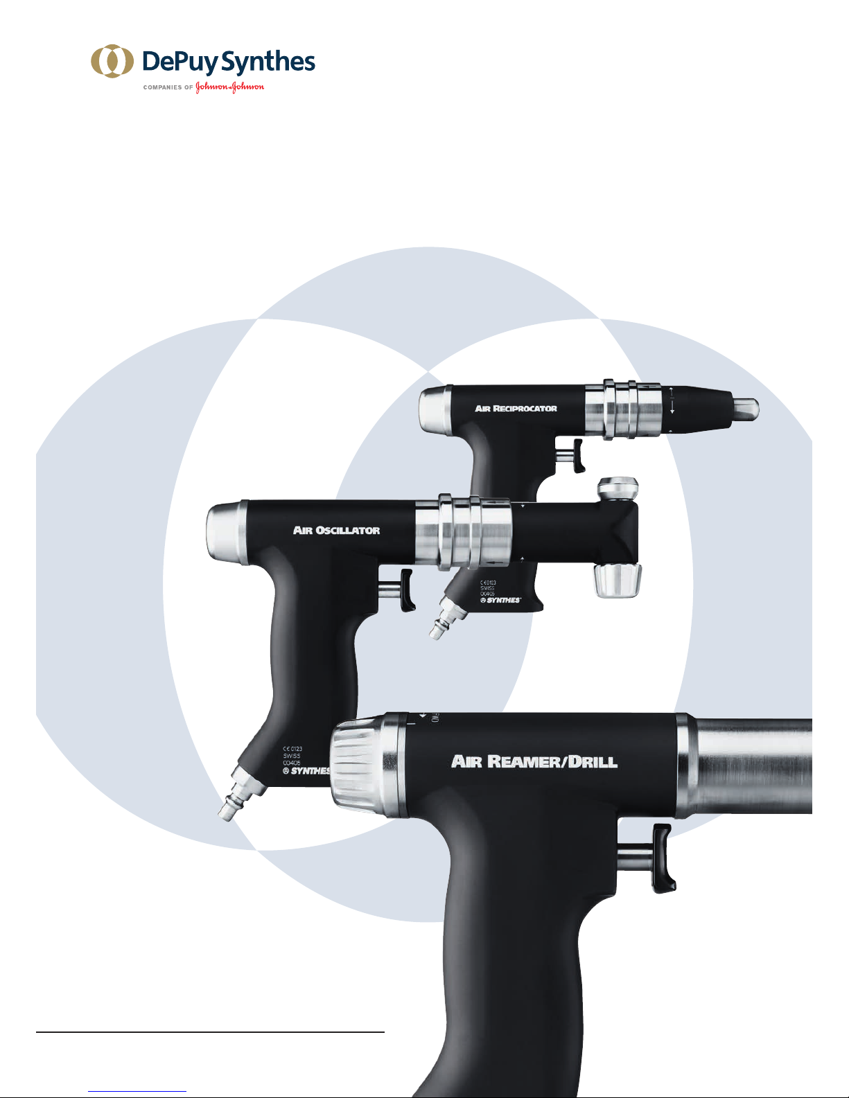
Accessories/Scope of delivery
The Air Power Line consists of three different handpieces, air
hoses and a range of attachments and accessories designed
for the system. Please refer to the “Ordering Information”
section for an overview of the components of the system.
To reach the specied performance only Synthes cutting
tools should be used. These are optimized to meet the spe-
cic requirements of the tool. Non Synthes saw blades can
considerably reduce the lifetime of the system.
Special auxiliaries such as cleaning brushes (516.101) and
Synthes Special Oil (519.970) are available for cleaning and
servicing the system.
No oils from other manufacturers may be used. Only Synthes
Special Oil (519.970) must be used to lubricate the power
tools and attachments. Lubricants with other compositions
may cause jamming, have a toxic effect or have a negative
impact on the sterilization results. Only lubricate the power
tool and the attachments when clean.
Precautions:
– Always wear personal protective equipment (PPE) includ-
ing safety goggles when handling with the Air Power Line
system.
– DO NOT use this equipment in presence of oxygen, ni-
trous oxide or a mixture consisting of ammable anes-
thetic and air (danger of explosion). Only use compressed
air or nitrogen for this equipment.
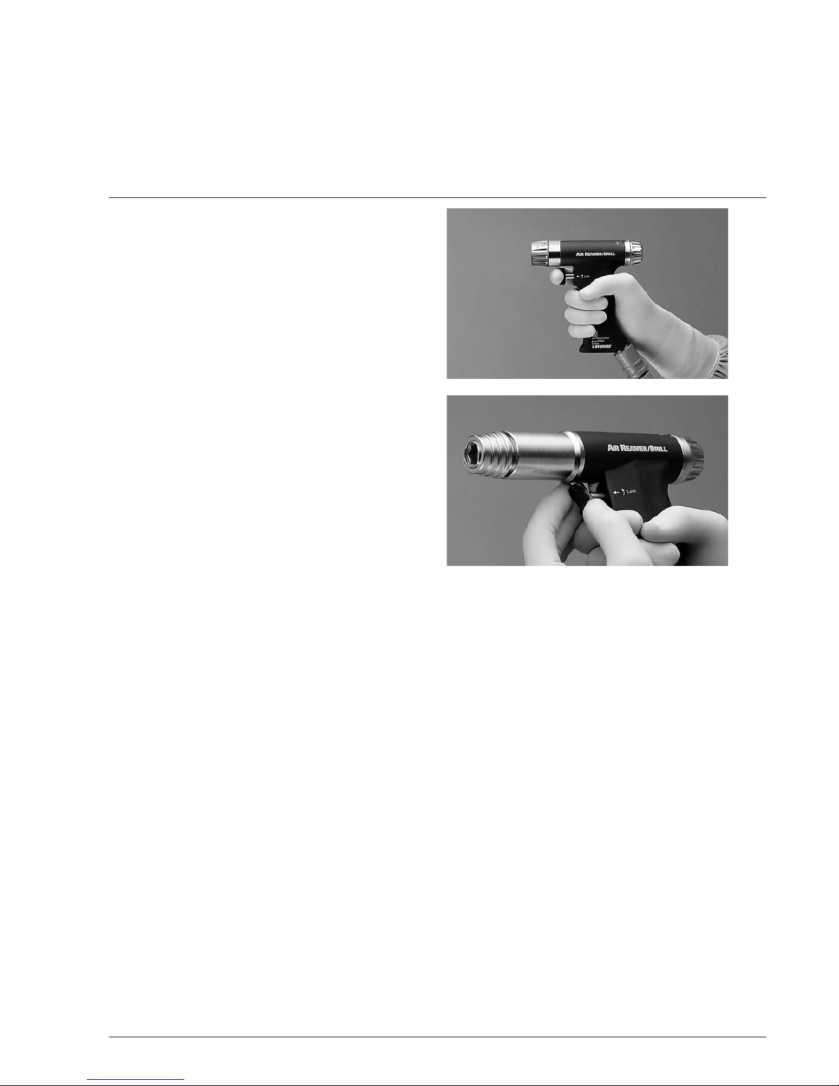
– To avoid injuries, the locking mechanism of the tool has to
be activated before every manipulation and before placing
the tool back down, i.e. the trigger has to be in the LOCK
position (refer to page 7, Safety system).
– Should the machine drop on the oor and have visible de-
fects, do not use it anymore and send it to the Synthes
Service Center.
– If a product drops on the oor, fragments may split off.
This represents a danger for the patient and user as:
– these fragments may be sharp.
– unsterile fragments may enter the sterile eld or hit the
patient.
– Should the system have corroded parts, do not use it any-
more and send it to the Synthes Service Center.
Introduction

Air Power Line II Instructions for Use DePuy Synthes 5
Explanation of symbols used
The following symbols are applied to the device or individual
components. Information on additional symbols is given in
the relevant sections of this document.
Caution
Read the provided Instructions for Use before
operating the device.
Do not reuse
Products intended for single use must not be
reused.
Reuse or reprocessing (e.g. cleaning and resteril-
ization) may compromise the structural integrity
of the device and / or lead to device failure,
which may result in patient injury, illness or
death. Furthermore, reuse or reprocessing of sin-
gle use devices may create a risk of contamina-
tion e.g. due to the transmission of infectious
material from one patient to another. This could
result in the injury or death of the patient or
user.
Synthes does not recommend reprocessing con-
taminated products. Any Synthes product that
has been contaminated by blood, tissue and / or
bodily uids / matter should never be used again
and should be handled according to hospital
protocol. Even though they may appear undam-
aged, the products may have small defects and
internal stress patterns that may cause material
fatigue.
SM_109761
This symbol indicates that the corresponding
device may not be immersed in liquids.
0123
The device meets the requirements of directive
93/42/EEC for medical devices. It is authorized
by an independent notied body for which it
bears the CE symbol.
Date of manufacture and manufacturer
Date of manufacture
non stérile Non sterile
Non sterile
The marked device shall only be used within
a specied temperature range.
Relative humidity
Atmospheric pressure
Do not use if package is damaged.

6 DePuy Synthes Air Power Line II Instructions for Use
Introduction
Startup of the
Air Power Line system
Removing the compressed air hose
Disconnect the hose by pulling back the hose coupling
sleeve.
Remove the air hose from the compressed air or nitrogen
source.
Precaution: The air hose has to be connected properly and
should never be squeezed or obstructed by any loads.
Non-respect might lead to bursting of the outer hose.
Connecting the compressed air hose to the handpiece
Attach the hose coupling over the air inlet nipple on the unit
up to the stop. The coupling will lock by itself with an
audible click.
Attach the other end of the air hose to the compressed air or
nitrogen source. Ensure that the coupling geometry of the
air hose is compatible with the geometry of the wall cou-
pling.
If the operating room does not have an exhaust air system
then use the Air Diffusor (519.950) to diffuse the air. The Air
Diffusor is connected between the source and the air hose.

Air Power Line II Instructions for Use DePuy Synthes 7
Working with
the Air Power Line system
Safety system
Air Power Line power tools have a safety system that pre-
vents unintentional operation.
To lock the trigger, pull it forward according to the marking
on the handle and then turn it. To unlock the trigger, twist it
in the opposite direction and then push it back.
Operating the trigger
The trigger smoothly regulates the speed of the Air Reamer/
Drill II (511.606) and the frequency of the Air Oscillator
(511.610) and the Air Reciprocator (511.615).

1
2
3
4
5
8 DePuy Synthes Air Power Line II Instructions for Use
Technical data is subject to tolerances.
Power Tool
Air Reamer/Drill II
1Attachment coupling
2Unlocking ring for attachment coupling
3Trigger and safety device
4Air inlet
5Knob for forward and reverse
Reverse operation of the Air Reamer/Drill II
The Air Reamer/Drill is equipped with a knob for forward
and backward 5.
By turning the knob in the indicated direction, the tool
switches from forward to reverse or vice versa.
Caution:
– Do not switch the direction of rotation while the tool is
operating.
– Use reverse only with tools that are approved for such
use. Otherwise the tool may break and cause damage.
Technical data
Rpm, without attachment: 0–340 rpm
Weight: 1,100 g
Air consumption at 6 bar: max. 380 l/min
Recommended operating pressure: 6 –7 bar (max. 10 bar)
Cannulation: B4.0 mm

Air Power Line II Instructions for Use DePuy Synthes 9
Please observe the safety instructions and warnings on the
relevant pages when working with attachments.
Mounting the attachments
Insert the attachment into the front of the attachment cou-
pling and turn until the positioning pins lock into the grooves
of the unlocking ring. Applying slight pressure, turn the at-
tachment clockwise until it has completely locked into posi-
tion. Check that it is tted properly by lightly pulling
the attachment.
Removing the attachments
Turn the unlocking ring for the attachment coupling 2
(see page 8) clockwise and remove the attachment.
Precautions: To prevent injury, the tool must be locked with
the safety system (see page 7) during each manipulation.
Make sure not to press the triggers when mounting and re-
moving the attachments.
Only use original attachments and tools from Synthes.
Damage that might arise from using attachments and tools
of other manufacturers is not covered by the warranty.
Properly functioning attachments are essential to the success
of an operation.
For this reason, used attachments must be checked for wear
and/or damage after each use and replaced if necessary.
Precaution: During reaming procedure, high torque values
must be provided by the power tool to the reaming head to
allow efcient bone removal. In cases where the reaming
head suddenly is blocked, these high torque values can be
transferred onto the user’s hand, wrist and/or the patient’s
body. In order to prevent injuries it therefore is essential that:
– The power tool is held in an ergonomic position with a
rm grip.
– If the reamer head blocks, the speed trigger is released
immediately.
– The correct function of the speed trigger (immediate stop
of the system when the trigger is released) is checked be-
fore the reaming process.
Attachments for the Air Reamer/Drill II

10 DePuy Synthes Air Power Line II Instructions for Use
Technical data is subject to tolerances.
Air Reamer/Drill II
Figure 2: Chuck with reaming speed (text REAM and red color marking)
Figure 1: Chuck with drilling speed (text DRILL and blue color marking)
Color marking on the attachments
Some rotating attachments are available in two different
speeds for drilling and reaming, respectively. The attach-
ments are marked accordingly (Figs. 1 and 2):
Drill attachments:
Blue color marking and inscribed with DRILL
All drilling speed attachments are geared to increase the
maximum drive speed to 930 rpm while reducing the maxi-
mum torque to 8.0 Nm.
Ream attachments:
Red color marking and inscribed with REAM
All reaming speed attachments transfer the speed and
torque of the drive unit with a maximum speed of 340 rpm
and a maximum torque of 20 Nm.

Air Power Line II Instructions for Use DePuy Synthes 11
Technical data is subject to tolerances.
AO/ASIF Quick Coupling (530.750)
(Speed: 0–930 rpm)
Trinkle Quick Coupling XXL, modified (530.795)
(Speed: 0–340 rpm)
Trinkle Quick Coupling (530.794)
(Speed: 0–930 rpm)
Quick Coupling for DHS/DCS Triple Reamers (530.760)
(Speed: 0–930 rpm)
AO/ASIF Quick Coupling for Reamer (530.780)
(Speed: 0–340 rpm)
Hudson Quick Coupling (530.782)
(Speed: 0–340 rpm)
Trinkle Quick Coupling (530.784)
(Speed: 0–340 rpm)
Hudson Quick Coupling (530.792)
(Speed: 0–930 rpm)
Trinkle Quick Coupling, modified (530.783)
(Speed: 0–340 rpm)
Trinkle Quick Coupling, modified (530.793)
(Speed: 0–930 rpm)

12 DePuy Synthes Air Power Line II Instructions for Use
Air Reamer/Drill II
Inserting the tools in the attachments
(on page 9)
Attaching cutting tools
Pull the unlocking sleeve on the attachment backwards (for-
wards for the DHS/DCS Quick Coupling, 530.760) and com-
pletely insert the tool (e.g. drill bit) by lightly turning it.
Once the tool is completely locked in place, release the un-
locking sleeve. Turn slightly to ensure that the tool is properly
locked into the coupling.
For the AO/ASIF Quick Coupling (530.750/530.780) the tool
can be inserted without moving the unlocking sleeve
(“click-in”).
Removing cutting tools
Pull the unlocking sleeve on the attachment backwards
(forwards for the DHS/DCS Quick Coupling, 530.760) and
remove the tool.
Caution: Properly operating tools are essential to the success
of an operation. For this reason, used tools must be checked
for wear and/or damage after each use and should be re-
placed if necessary.

1
3
2
Air Power Line II Instructions for Use DePuy Synthes 13
Technical data is subject to tolerances.
Quick Coupling for Guide Pins B1.5 to 4.0 mm
(510.790)
(Speed: 0–930 rpm)
Load the guide pin and insert into the bone
1. Adjust the adjusting sleeve 3 to t the diameter of the
guide pin to be used. Slightly press the adjusting sleeve
axially against the tool and rotate the sleeve.
2. Apply a slight amount of pressure to insert the guide pin
from the front or back into the cannulation 1. The guide
pin is held automatically.
3. Adjust the working length by pulling on the guide pin.
4. To t the guide pin pull the tension lever 2 against the
tool. Only pull the tension lever against the tool as much
as necessary. The clamping force can be varied by pulling
and releasing the clamping lever.
5. Insert the guide pin into the bone. Apply the clamping
force as long as the guide pin is advanced.
6. To regrip the guide pin, reduce the clamping force and
move the tool to the desired length. Reclamp the guide
pin by pulling on the tension lever.
The guide pin is removed from the bone analogue as
described above.

14 DePuy Synthes Air Power Line II Instructions for Use
Drill Chuck (530.731)
Drill Chuck (530.732)
Spare key (510.191)Drill Chuck (530.730)
Air Reamer/Drill II
Drill Chuck with key (530.732)
(Speed: 0–340 rpm)
Accept round and triangular shafts up to B7.3 mm
Loading tools into the chuck
Drill chuck with key (530.730, 530.732)
Open the clamps of the drill chuck with the key provided
(510.191): Insert the key into the suitable shaft and turn anti-
clockwise. Insert the shaft of the tool into the centre of the
opened chuck.
Close the chuck in reverse order.
Ensure that the shaft of the tool is tted between the centre
of the three clamps of the chuck. Turn the key clockwise to
tighten. The teeth of the key must be properly seated in the
gear of the drill chuck. The teeth of the chuck and of the key
must not be worn.
Drill Chuck, keyless (530.731)
Open the clamps manually be holding the retaining ring and
turning the securing ring clockwise. Insert the shaft of the
tool into the centre of the opened chuck. Lock and tighten
the chuck by holding the retaining ring and turning the
securing ring clockwise. Ensure that the shaft of the tool is
loaded between the centre of the three clamps of the chuck.
Drill Chuck with key (530.730)
(Speed: 0–930 rpm)
Drill Chuck, keyless (530.731)
(Speed: 0–930 rpm)

Air Power Line II Instructions for Use DePuy Synthes 15
Technical data is subject to tolerances.
Caution: Do not allow the tools tted in the keyless Drill
Chuck to rotate backwards, as the Drill Chuck can otherwise
open.
Use the Drill Chuck with Key for reverse mode (530.730,
530.732).
Precaution: To ensure secure xation of the instrument,
make sure the toothed rims on the drill chuck and key are
not worn.
Replace damaged or worn components. Only use original
Synthes key.
Removing cutting tools
Drill Chuck with key (530.730, 530.732)
Release the chuck by turning the key (510.190) anticlockwise
and remove the tool. The teeth of the chuck and of the key
must not be worn.
Universal Drill Chuck, Keyless (530.731)
Hold the Drill Chuck on the retaining ring and release the
securing ring by turning anticlockwise. Remove the tool from
the Drill Chuck.

16 DePuy Synthes Air Power Line II Instructions for Use
Air Reamer/Drill II
Figure 1
Radiolucent Drive (511.300)
Inserting the drill
Pull the ring on the attachment forward, and push the drill
into the coupling as far as it can go while rotating it slightly
(Fig. 1). Push the ring on the attachment back to x the drill.
Check if the drill is seated correctly by gently pulling on it.
For removal, follow the same procedure in reverse.
Coupling the Radiolucent Drive to the power tool
Attach the Adapter for Radiolucent Drive (530.741) to the Air
Reamer/Drill II (for information please refer to page 9,
Mounting the attachments). Push the Radiolucent Drive as
far as it will go over the quick coupling and the adapter, and
rotate it into the desired working position. Support the drive
with your free hand.
For removal, follow the same procedure in reverse.
Adapter for Radiolucent Drive (530.741)

Air Power Line II Instructions for Use DePuy Synthes 17
Using the Radiolucent Drive
Before positioning the Radiolucent Drive, align the image
intensier until the distal locking hole of the medullary nail is
round and easily visible.
After the incision, position the Radiolucent Drive and center
the drill bit tip over the locking hole. On the monitor of the
image intensier, you can see both the drill bit and the tar-
get rings of the drive.
Swing the drive up and center it precisely so that the drill bit
appears as a round point and the locking hole is visible
around it. The target rings also assist centring. The locking
hole can now be drilled directly.
For further information on the Radiolucent Drive and on
the special 3-flute spiral drill bits please consult the relevant
Instructions for Use (036.000.150) or your local Synthes
office.
Notes: Grip the coupled Radiolucent Drive tightly when
switching on the power tool, particularly if the power tool is
held face down.
– Only special 3-ute spiral drill bits can be used. Your
Synthes representative will provide you with additional
information on which drill bits can be used.
– Handle the Radiolucent Drive with great care. Do not
allow contact between the drill bit and the medullary nail.
– Depending on the setting of the image intensier, a zone
may appear in the rear of the Radiolucent Drive that is not
radiolucent. However, this does not inhibit aiming and
working with the device.
– To protect the gears, the Radiolucent Drive is equipped
with a slip clutch that disengages in case of an overload
and emits an audible rattling noise.
– The following procedures can cause an overload:
– Correcting the drilling angle when the cutting edge
of the drill bit are completely in the bone.
– Hitting the nail with the drill bit.
– Drilling can continue after making the following
corrections:
– Correcting the drilling angle: Remove the drill bit until
the utes are visible and then restart the drilling.
– Hitting a nail: Remove the drill bit until the utes are
visible, and reaim the drill bit or ex change the drill bit
if necessary.

1
2
3
4
18 DePuy Synthes Air Power Line II Instructions for Use
Technical data is subject to tolerances.
Power Tool
1Locking knob for the saw blade quick coupling
2Sliding sleeve for positioning the saw head
3Trigger and safety device
4Air inlet
Technical data
Continuously adjustable frequency: 0–14000 1/min
Weight: 1,260 g
Air consumption at 6 bar: max. 380 l/min
Recommended operating pressure: 6–7 bar (max. 10 bar)
Saw blade deflection: 4.5°
Air Oscillator
Other manuals for Air Power Line II
2
Table of contents
Other Synthes Paint Sprayer manuals
Popular Paint Sprayer manuals by other brands

Daewoo
Daewoo DAPSP5L user manual

AG SPRAY
AG SPRAY BRONZE25 owner's manual

Campbell Hausfeld
Campbell Hausfeld AL1860 - METAL Operating instructions and replacement parts list

KREA Swiss
KREA Swiss multiSPRAY operating instructions

Graco
Graco 295530 Operation, parts, service and repair

Maruyama
Maruyama MSD41 Operator's manual