Synway ATP2410-8 User manual

ATP2410 Recording Server
ATP2410-8
ATP2410-16
ATP2410-24
Analog Call Recording Server
Version 4.0.0.0

Content
Content ....................................................................................................i
Revision History....................................................................................iii
Chapter 1 Overview..........................................................................1
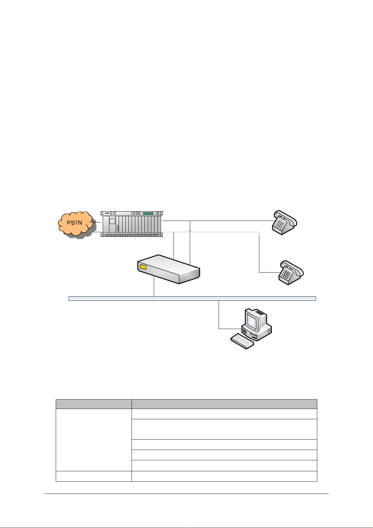
1.1 Typical Application ......................................................................................... 1
1.2 Feature List.................................................................................................... 1
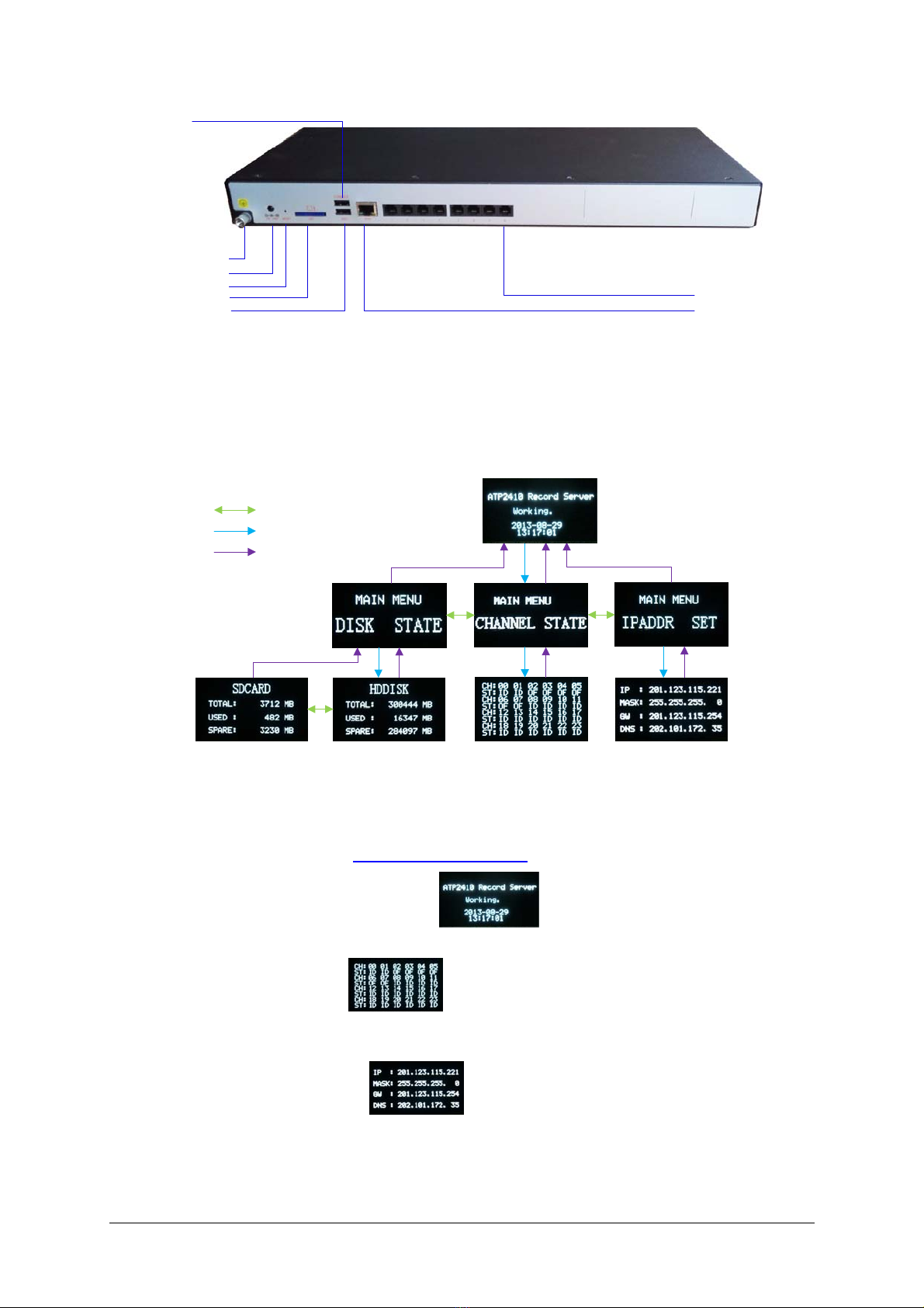
1.3 Product Appearance ...................................................................................... 3
1.4 Button Operation............................................................................................ 4
Chapter 2 Installation.......................................................................6
2.1 Package List .................................................................................................. 6
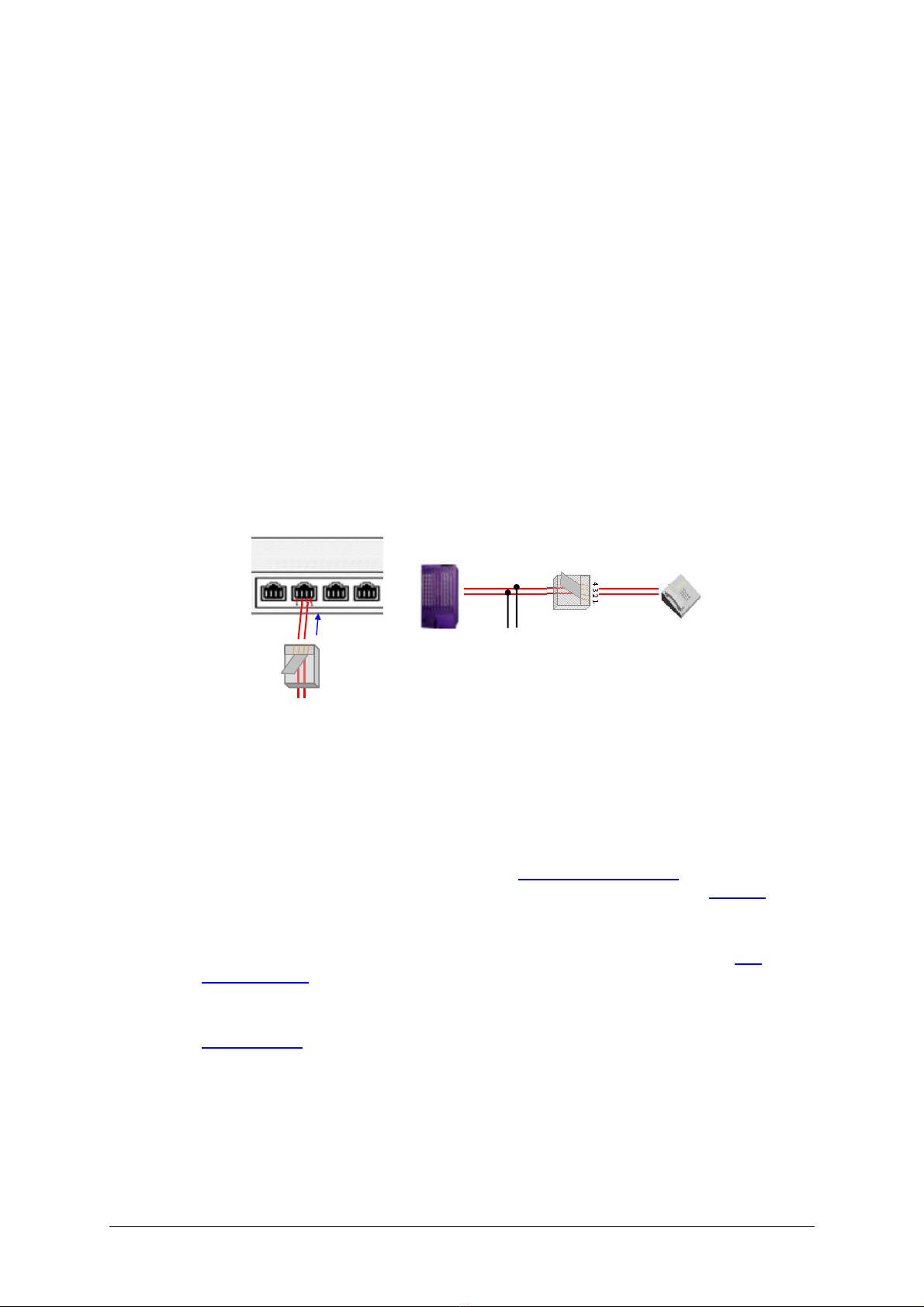
2.2 Installation Procedure .................................................................................... 6
2.3 Quick Guide ................................................................................................... 6
Chapter 3 Instructions .....................................................................8
3.1 System Login ................................................................................................. 8
3.2 Channel State ................................................................................................ 9
3.3 Recoding Options ........................................................................................ 12
3.3.1 Recording Inquiry....................................................................................................12
3.3.2 Recording Parameters ............................................................................................15
3.3.3 DVD Writer..............................................................................................................16
3.4 System Settings........................................................................................... 17
3.4.1 System....................................................................................................................18
3.4.2 Storage ...................................................................................................................19
3.4.3 Number...................................................................................................................22
3.4.4 IP ............................................................................................................................25
3.4.5 Debugging Log .......................................................................................................25
3.4.6 Alarm ......................................................................................................................27
3.4.7 Time........................................................................................................................28
3.4.8 SNMP .....................................................................................................................29
3.4.9 Remote Update.......................................................................................................30
3.4.10 WEB Settings..........................................................................................................30
3.5 User Management ....................................................................................... 30
3.6 Info Management......................................................................................... 33
3.6.1 Station Management...............................................................................................34
3.6.2 Customer Management ..........................................................................................36
3.7 Statistics Report........................................................................................... 40
3.8 Operating Log .............................................................................................. 41
3.9 Change Password ....................................................................................... 42
3.10 Database Management ............................................................................... 42
3.10.1 Database Settings ..................................................................................................43
3.10.2 Database Restore...................................................................................................44
3.11 Centralized Management............................................................................. 44
3.11.1 Management...........................................................................................................45
3.11.2 Master/Slave Settings.............................................................................................47
ATP2410 User Manual (Version 4.0.0.0) Page i

ATP2410 User Manual (Version 4.0.0.0) Page ii
3.12 Reboot&Reset ............................................................................................. 48
3.13 FTP Feature................................................................................................. 49
3.14 Real-Time Monitoring................................................................................... 50
3.14.1 Install “RemoteListener”..........................................................................................50
3.14.2 Monitor a Channel ..................................................................................................51
3.14.3 Use Monitoring Tool ................................................................................................51
3.15 Alarm Info .................................................................................................... 51
3.15.1 SD Card Alarm........................................................................................................51
3.15.2 Disk Abnormal Alarm ..............................................................................................52
3.15.3 Long Time No Recording Alarm..............................................................................52
3.15.4 Channel Off-line Alarm............................................................................................52
3.15.5 RecSvr Abnormal Alarm..........................................................................................52
3.15.6 Slave Device Off-line Alarm ....................................................................................53
3.15.7 Database Damage Alarm........................................................................................53
Appendix A Technical Specifications.................................................54
Appendix B Troubleshooting..............................................................55
Appendix C Technical/sales Support.................................................56

Revision History
Version Date Comments
Version 3.1.0.0 2016-7 Initial publication
Version 4.0.0.0 2016-9 New Revision
ATP2410 User Manual (Version 4.0.0.0) Page iii

Chapter 1 Overview
Thank you for choosing ATP2410 Recording Server!
The ATP2410 series recording servers (hereinafter referred to as ‘recording server’) support
continuous 24-hour independent recording of analog calls, saving call records and audio files in
the hard disk. Each call record includes the start time and the end time, phone numbers of the two
parties, call length, station information, channel number, etc. They support online management,
that is, allow users to do such operations as modifying configurations, checking real-time status,
querying recording files, backing up files, recording and burning files through WEB. They are in
hardware equipped with OLED display and configuration buttons for users to query channel state
and hard disk information, and to modify IP address, eliminating the need of PC, and with the LED
indicator to tell the state of channels and devices. Also they provide the DLL and webservice
interfaces for configuration and information inquiry. At present the ATP2410 series has three
modules, ATP2410-8, ATP2410-16 and ATP2410-24 which contain 8, 16, 24 channels
respectively.
1.1 Typical Application
Phone
Phone
Subscriber
Terminal
PBX Recoding line
parallel circuit
LAN
Recording
Server
Figure 1-1 Typical Application
1.2 Feature List
Feature Description
Single/multi query items support.
Query items include channel number, caller number, called number,
recording time, recording length, call direction, call type (toll/local), etc.
Query results can be exported to Excel.
Remarks can be added on recording items.
Recording Inquiry
Recording files can be played, downloaded, and deleted
Call Monitoring Real-time call monitoring (only available to privileged users).
ATP2410 User Manual (Version 4.0.0.0) Page 1

Single/multi count terms support, including: caller number, called
number, recording time, recording length, call direction, call type
(toll/local), etc.
Statistical reports can give the amount and length of total calls, toll calls,
local calls, outgoing calls, incoming calls and missed calls, as well as
the average call length.
Statistical Report
Statistical reports can be exported to excel.
System Operation Log System operation logs record the operating time and details of both the
client and the server.
The settings include file format, compressed format, silence threshold,
alarm condition, etc.
Five recording start conditions are optional: Voltage, Barge-in, DTMF,
Always Recording and Voltage (after call connection). Each channel is
supported to set independently.
Recording Parameters
Support up to 3 recording periods.
Automatically scan all the disks and calculate capacity.
Save data into the next disk once the current is full.
Disk Management
Give an alarm or delete part of the data when all disks are full.
Automatically backup recording data to a designated disk everyday
once set.
Support the set of backup expires. After the due time, the backup files
will be deleted automatically.
Recording Backup
Automatically delete the earliest files when the disk space is less than
the preset lower limit.
User information can be added, deleted or modified. There is no limit in
the amount of system users.
User Management
Different authorities can be customized for different WEB users.
Phone number and station number can be set for a channel.
Each channel can be set separately with a recording direction (record
all, record none, record incoming calls only or record outgoing calls
only).
Setting values for a channel can be applied to all if necessary.
Channel Parameters
Offline alarm can be set for a designated channel.
A certain number or numbers with a certain prefix can be designated for
recording.
Conditions can be set for recognization of area codes.
Batch adding of number information is supported.
Number Filtering
A certain number or numbers with a certain prefix can be designated for
pop-up display of call information.
Station information can be added, deleted or modified.
Station Management
Station information can be exported to Excel.
ATP2410 User Manual (Version 4.0.0.0) Page 2

Station information can be imported from Excel.
Customer information can be added, deleted or modified.
Customer information can be exported to Excel.
Customer Management
Customer information can be imported from Excel.
Audio alarm, pop-up display alarm and mail alarm are available.
Multiple alarming conditions are optional: SD Card Alarm, Disk
Abnormal Alarm, Long Time No Recording Alarm, Channel Off-line
Alarm, RecSvr Abnormal Alarm, Slave Device Off-line Alarm, Database
Damage Alarm.
Alarming
Support auto restart when error occurs in software.
Reboot&Reset Support reboot and reset of the recording server.
Driver Configuration Driver configuration can be queried or modified through the web page.
Support remote modification of the IP address of RecSvr.
Remote Modification Support remote modification of time and date on RecSvr.
Centralized Management Support of a master device (PC or ATP2410 recording device) to
manage all slave devices in the network.
Support auto backup of database. Once set, the system will regularly
back up tables in the database.
External interfaces to database can be opened via configuration.
Database Management
Database can be restored to a previous backup on a designated time.
High Impedance
Recording
Support recording in different environments with varied call density,
widely applicable to such occasions as the call recording system and
the call center monitoring system.
Support detection of both DTMF and FSK.
Tone Detection Configurable tone detector is provided to detect all type of tones.
Voltage Detection Line voltage can be automatically detected and displayed on the web
page.
Record & Burn Select a recording file to burn.
Webservice Interface Configure the webservice interface, with the default value of 80.
1.3 Product Appearance
ESC Button
LAN Indicator
HDD Indicator
OK Button
+/- Button
Channel Indicator
Run Indicator
Alarm Indicator
Power Indicator
OLED Screen
Figure 1-2 Front Panel
ATP2410 User Manual (Version 4.0.0.0) Page 3

RJ11
DVD Interface
Power Interface
Grouding Stud
Network Interface
SD Card Interface
Console
Reset Button
Figure 1-3 Rear Panel
1.4 Button Operation
The recording Server is equipped with configuration buttons and OLED display through which
users can query the operating status and configure the IP address. The button operations are
demonstrated in Figure 1-4 below.
图例: +/-
OK
ESC
Figure 1-4 Button Operation
Note:
1. The images in the flow chart are the actual interfaces on the OLED display. The arrows and
corresponding legends indicate the button presses and directions. For exact location of the
buttons on the panel, refer to 1.3 Product Appearance.
2. The word ‘Working’ in the main interface shall be ‘Booting’ instead during the
starting process.
3. In the channel state interface , CH represents channel number while ST indicates
state. The abbreviations and corresponding meanings of the channel states are: ID (Idle), OF
(Offline), RI (Ringing) and PI (Pickup).
4. In the IP configuration interface , users can modify the IP address. The flashing
field in the interface is the current field to be set. Use the ‘+/-’ button to modify it. Press the
“OK” button to go to the next field. After all fields are configured, press “ESC” button to save
the settings and return to the main IP configuration interface.
ATP2410 User Manual (Version 4.0.0.0) Page 4

ATP2410 User Manual (Version 4.0.0.0) Page 5

ATP2410 User Manual (Version 4.0.0.0) Page 6
Chapter 2 Installation
2.1 Package List
ATP2410 Series Recording Server *1, with a 500G 2.5-inch hard disk
Foot Bracket*2, Rubber Foot Pad*4, Screw for Foot Bracket*8
User Manual *1
+19V DC Power Supply *1
2.2 Installation Procedure
Step 1: Connect the +19V DC power line.
Step 2: Connect the network cable.
Step 3: Plug one end of a phone line into an RJ11 jack for the corresponding channel
on the recording server and connect the other end parallelly to any position
between the PBX and the telephone.
Figure 2-1 Line Connection
Step 4: Check the state of the channel connected in Step 3 through the OLED display.
If the channel is in the state ID (Idle), it indicates the connection is normal;
otherwise, the channel is not available, and you should check if there is
something wrong with the connection.
Step 5: Modify the IP address through the configuration buttons on the recording
server. For detailed instructions, refer to 1.4 Button Operation. (Note: The IP
address can also be modified through the WEB interface, refer to 3.4.4 IP for
detailed instructions and default IP values.)
Step 6: Type in the IP address set in Step 5 into the browser and enter the Recording
Management Software. For detailed instructions about login, refer to 3.1
System Login.
Step 7: Check through the WEB interface if the hard disk is formatted. If not, format it
before use. For detailed instructions about formatting the hard disk, refer to
3.4.2 Storage.
2.3 Quick Guide
After completing the above steps, you can well run the recording server. The default values of the
main recording parameters are listed here below.
Recording Start Condition: Voltage
4 3 2 1
Ch11 b
Ch11 a
PBX Phone
Ch11 a
Ch11 b

ATP2410 User Manual (Version 4.0.0.0) Page 7
Compression Format: G711-A
File Format: wav
Recording Period: 24 hours
Recording Direction: Record all
To modify the recording parameters, refer to 3.3.2 Recording Parameters.
Note:
1. We suggest that you change the initial password after your first login. For detailed instructions
about changing the password, refer to 3.9 Change Password.
2. To perfect the recording information, you need to add corresponding station and customer
information. For detailed instructions, refer to 3.6 Info Management.
3. The detailed configurations and operations of the recording server will be introduced in
Chapter 3 Instructions.
Special Instructions:
When an alarm buzzes, it should be promptly handled according to the user manual.
Otherwise it may lead to a drop in performance or unexpected errors.
The case of the recording server must be grounded for safety reasons, according to
standard industry requirements. The grounding studs on the machine guarantee
effective earthing. No or improper grounding may cause instability in operation as well as
decrease in lightning resistance.

Chapter 3 Instructions
3.1 System Login
Type the IP address into the browser and enter the login interface. See Figure 3-1.
Figure 3-1 Login Interface
The recording management software has an initial administrator whose user name is ‘admin’ and
initial password is ‘admin’ too.
After login, you can see the main interface as below.
Figure 3-2 Main Interface with All Features
For users owning all authorities, all features in Figure 3-2 are available. For other users, only the
authorized features are shown on this page.
All users can change their password for safety reasons and those with system setting authorities
can modify the IP address of the recording server to put it in the same network segment with the
PC to avoid repeated modification on every visit. For more instructions about IP modification, refer
to 3.4.4 IP.
ATP2410 User Manual (Version 4.0.0.0) Page 8

3.2 Channel State
Figure 3-3 Channel State Interface
See Figure 3-3 for the channel state interface. The above list shows the operating states of all
recording channels. Each channel supports customer and station information inquiry as well as
real-time monitoring. The table below explains the query items in Figure 3-3.
Item Descriptions
Monitor
The icon appearing in the Monitor column indicates that the channel is
recording. Click it and you can monitor the call on this channel in real time. For
detailed operations, refer to 3.14 Real-Time Monitoring.
Ch No. Logical channel number in the recording server.
Voltage Line voltage on the corresponding channel.
State Channel state. Each channel has 4 states (see Figure 3-3): Idle, pickup, ringing,
off-line.
Remote Phone
The number of the remote phone in conversation with the monitoring end. If this
number and its corresponding customer information exist in the database, click it
and you can see the customer information (See Figure 3-4). For instructions about
adding or modifying customer information, refer to 3.6.2 Customer Management.
DTMF DTMF digits pressed on the remote phone and the phone which is connected to the
recording line.
Station
Station number corresponding to the channel. If the station information exists in the
database, click it and you can see station information (See Figure 3-5). For
instructions about adding or modifying station information, refer to 3.6.1 Station
Management. Station, as well as Monitored Phone and Remarks, can be
modified by Modify.
Name Station name corresponding to the channel.
Monitored Phone The phone number monitored by the recording channel. It can be modified by
Modify.
Call Direction
Call direction of the current conversation, taking the monitoring end as reference.
That is, if the monitoring end is the calling party, Call Direction column displays the
call out icon; otherwise, it displays the call in icon.
Start Time
The start time of the current recording. Please note that not all the recording pieces
shown on this page will be saved. Whether a recording to be saved or not depends
on multiple judging conditions. Go to the recording inquiry interface to get the exact
saved recording data. For detailed instructions about querying, refer to 3.3.1
Recording Inquiry.
Length Length of the current recording, calculated by s.
Remarks Remarks about the channel, regarded as a mark of different channels. It can be
ATP2410 User Manual (Version 4.0.0.0) Page 9

modified by Modify.
If there are remote phones and corresponding customer information existing in the database, click
one and you can see the customer information interface as below.
Figure 3-4 Customer Info Pop-up
If there are stations and corresponding station information existing in the database, click one and
you can see the station information interface as below.
ATP2410 User Manual (Version 4.0.0.0) Page 10

Figure 3-5 Station Info Pop-up
Click Modify in Figure 3-3 to modify information of the corresponding channel. See Figure 3-6 for
the channel info modification interface.
Figure 3-6 Channel Info Modification Interface
The items Monitored Phone, Station and Remarks in Figure 3-6 have the same values as those
in the Channel State Interface. Other items are explained in the table below.
Item Description
Rec Direction Sets calls on which direction will be recorded. Four options are now available:
Option Description
Incoming calls only Taking the monitoring end as reference, only record the incoming
ATP2410 User Manual (Version 4.0.0.0) Page 11

calls.
Outgoing calls only Taking the monitoring end as reference, only record the outgoing
calls.
Record all Taking the monitoring end as reference, record both the incoming
and outgoing calls.
Record none Taking the monitoring end as reference, record neither the
incoming nor the outgoing calls.
Note: This item is valid only when the Recording Start Condition is not set to
Always recording (Refer to 3.3.2 Recording Parameters).
Alarm for Offline Sets the offline alarm for the channel.
Apply on Other Ch Apply the setting values of Recording Direction and Alarm for Offline to other
channels.
After configuration, click Save to save the above settings into the database; click Close to cancel
the settings. The settings will not go into effect until you reboot the recording service. For the
instructions about rebooting the recording server through WEB, refer to 3.12 Reboot&Reset.
3.3 Recoding Options
Recording options include three parts: Recording Inquiry, Recording Parameters and DVD
Writer. The part Recording Inquiry provides multiple items for users to find the needed recording
files rapidly. The part Recording Parameters offers global settings for the recording server, which
can be configured according to individual requirements. The part DVD Writer offers the interface
to write the required recording file onto DVD.
3.3.1 Recording Inquiry
Figure 3-7 Recording Inquiry Interface
See Figure 3-7 for the recording inquiry interface. Users can inquiry the recording files using the
combination of multiple query items. The table below explains the query items in Figure 3-7.
Item Description
Start Date; Start Time;
End Date; End Time
Time period of the recording, including time and date. For example, the recording
in the above figure is required to start from 2016-06-28 00:00:00 and end at
2016-07-05 23:59:59. Please note that the end time and date should not be
earlier than the start time and date.
ATP2410 User Manual (Version 4.0.0.0) Page 12

Call Direction Used as a condition to filter recoding files. Three options are available: All, Call
in, Call out, taking the monitoring end as reference. The default value is All.
Recording Length
Length of the recording, used as a condition to filter recoding files. Three options
Unlimited, Longer than and Shorter than are available. The default value is
Unlimited, which means there is no limit on this item. To choose Longer than or
Shorter than, you should enter the exact time length in the edit box (calculated
by s). Once set, only the qualified recordings will be displayed.
Station No.; Station
Name
;
Station Branch
Station information. Refer to 3.6.1 Station Management. If a station is bound with
a channel, the recording files generated on that channel will contain the station
information. Users can search for the recording files based on Station No.,
Station Name or Station Branch. These three fields can be left empty, which
means ignoring this filter condition. Suggest: Do not fill in both fields at the same
time.
Customer Phone;
Customer Name
Customer information. Refer to 3.6.2 Customer Management. If the remote
phone number matches the customer information in the database, the recording
files about this number will contain the customer information. Users can search
for the recording files based on Customer Phone or Customer Name. These two
fields can be left empty, which means ignoring this filter condition. Suggest: Do
not fill in both fields at the same time.
CallerID; CalleeID Used as a condition to filter recoding files. Just enter the number you want to
query.
Played Whether the recording file has been played. There are three options Unlimited,
Yes, No, and the default value is Unlimited.
Channels
Designate the range of channels you want to query. The two combo boxes from
left to right indicate the start and end channels respectively. Please note that the
start channel number should not be larger than the end channel number. If the
two channel numbers are the same, only this channel will be required. The
default value is all channels.
Call Type Used as a condition to filter recoding files. Three options All, Local, Toll are
available, and the default value is All which indicates ignoring this filter condition.
Missed Call Whether the calls to be inquired should be missed calls or not. There are three
options Unlimited, Yes, No, and the default value is Unlimited.
DTMF DTMF digits in the recording, used as a condition to filter recoding files.
Query Range
Sets the range for data query, including two options: Latest 100,000 records and
All records. The default value is Latest 100,000 records as it is time-consuming
to inquire all recording files.
Sort by
Determines the sort order of the query result. It can be the ascending or
descending order of Recording Time, Recording Length or Station No., with the
default value of the ascending order of Recording Time.
Remarks Remarks in the recording, used as a condition to filter recording files.
After the configuration of the above query items, click ‘Inquiry’ to obtain the query results (See
Figure 3-8); click ‘Reset’ to restore the configurations.
ATP2410 User Manual (Version 4.0.0.0) Page 13

Figure 3-8 Recording Query Results
The recording query results include Channel No., Call Direction, Missed Call or not, CallerID,
DTMF, CalleeID, Recording Start Time, Recording Length, Station No., Station Name,
Customer Phone, Remarks&Sign and Add Customer Info of each recording item. On this
interface, users can do the following operations:
Operation Description
Export the query results to Excel. Due to the upper limit of Excel 2003, the recording
server only supports exporting up to 65535 items. A prompt will pop up once the
number of items you export exceeds 65535.
Export
Play the recording file. See
Figure 3-9 for the player interface. The icon in the Play column has three colors:
blue indicates that the recording file has not been played; orange indicates it has
been played; and grey indicates it has been deleted and cannot be played.
Play
Download the recording file to local. If the icon in the Download column is grey, it
indicates that the file has been deleted and cannot be downloaded. Refer to 3.13
FTP Feature for the rule of the system to name the downloaded recording file.
Download
Click ‘Station’ Link See corresponding station information in the prompt.
Click ‘Customer’
Link See corresponding customer information in the prompt.
Click
‘Remarks&Sign’
Link
Modify the remarks, and mark the recording file to be important, retain or both.
Add Customer Info
Add the corresponding customer number to this column. If the icon is green, click it
to add; if the icon is grey, it indicates the customer number is unavailable or has
been added.
The recording file player interface:
Figure 3-9 Recording File Player Interface
Note: If your current browser fails to play the audio file as it can not well support the playing plugin,
please change to another browser and try again.
ATP2410 User Manual (Version 4.0.0.0) Page 14

To delete a recording file, check the corresponding checkbox in
Figure 3-8 and click the ‘Delete’button. After deletion, the checkbox in the Select column will turn
grey and the recording file become unplayable and undownloadable. Check All means to select
all available items in the current page; Uncheck All means to cancel all selections in the current
page; Inverse means to uncheck the selected items and check the unselected.
3.3.2 Recording Parameters
Figure 3-10 Recording Parameter Configuration Interface
See Figure 3-10 for recording parameter configuration. Users can configure the parameters
depending on actual requirements. The table below explains the items in Figure 3-10.
Item Description
Select Channel Select the current channel to be configured.
Recording Start
Condition
There are five options available: Voltage, Barge-in, DTMF, Always Recording and
Voltage (after call connection).
Recording Start
Condition Description
Voltage Start recording once pickup operation is detected.
Barge in Start recording once Barge-in is detected.
DTMF Start recording once valid DTMF key combination is detected.
Always recording Never stop recording since the recording service starts.
Voltage (after call
connection)
To select this option, you have to enable the polarity reversal
feature first. If this option is selected, the recording will not start
until the called party picks up the call, and it only contains the
data of conversation, excluding the dialing tone.
Note: When the “Always recording” mode is selected, the recording management
software will by default generate a recording file at the end of each 50-minute
recording. Before each recording file is formally generated, it can be found neither
in the Recording Inquiry interface nor under the Record directory in FTP, but its
temporary file can be found under the temp directory in FTP.
DTMF Key
Combination
This item is valid only when the Recording Start Condition is set to DTMF. The
system will start recording once the DTMF key combination are pressed in the right
order.
Minimum Recording
Length
Only when the recording time exceeds the set value of this parameter will the
recording be saved into a file. Range of value: 1~60s.
Compression
Format
The compression format of the recording files. Currently G.711μ, G.711, ADPCM
and G729A are supported.
File Format The save format of the recording files. Currently only wav and vox are supported
ATP2410 User Manual (Version 4.0.0.0) Page 15

and the default format is wav. The vox file has no file header, only saves the
recording data and cannot be played through WEB. Therefore, if you need to play
the file through WEB, choose the format wav for it.
Largest Interval
between Dialing
Codes
Sets the largest interval (calculated by s) between dialing codes, mainly used for
the occasion that the monitoring end works as the calling party. If all the DTMF
digits are pressed within this interval and before the ringback tone is detected, they
will all be regarded as the remote number. Otherwise, only the digits pressed before
timeout and the detection of ringback tone will be regarded as the remote number.
Largest Interval
between Combined
DTMF Keys
Sets the largest interval (calculated by s) between combined DTMF key presses.
For example, provided this value is set to 5 and the DTMF Key Combination is set
to ‘*1’, if the time interval between the detection of ‘*’ and ‘1’ is larger than 5s, the
key combination will be regarded as invalid and not start the recording. Only if each
interval between every two key presses of the complete DTMF combination is less
than 5s will the recording server regard them as valid DTMF key combination and
start recording. This item is valid only when the Recording Start Condition is set
to DTMF.
Sets the recording periods. It can be recording in 24 hours or in designated time
periods. To make recording all the time, select ’24 hours’. To designate time periods
for a recording, check one or several (up to 3) period checkboxes and enter
corresponding time ranges.
Choose Recording
Period
After configuration, click Save to save the above settings into the database; click Reset to restore
the configurations. The settings will not go into effect until you reboot the recording service. For
the instructions about rebooting the recording server through WEB, refer to 3.12 Reboot&Reset.
3.3.3 DVD Writer
ATP2410 User Manual (Version 4.0.0.0) Page 16
This manual suits for next models
2
Table of contents
Popular Server manuals by other brands

Gigabyte
Gigabyte H261-H60 user manual

8e6 Technologies
8e6 Technologies TAR S (5K02-62) quick start guide

Compaq
Compaq TruCluster Server AA-RHGWC-TE manual

Supermicro
Supermicro SuperServer 2028GR-TR Quick reference guide

IntesisBox
IntesisBox Modbus Server-ATERSA installation manual

Tangent
Tangent Pillar 1600i Specifications