AIC SB405-PV User manual

UM_SB405-PV_v1_060518
SB405-PV
Storage Server Barebone
User's Manual

Chapter 3. Motherboard Settings............................................. 41
3.1 Motherboard Block Diagram ..........................................................41
3.2 Motherboard Placement .................................................................42
3.3 Motherboard Content List................................................................43
3.4 Internal Connectors/Jumpers .........................................................44
3.5 LEDs....................................................................................................49
Chapter 4. BIOS Conguration Settings................................... 53
4.1 Updating BIOS...................................................................................55
Chapter 5. BMC Conguration Settings................................... 57
5.1 Method 1 (Use the BIOS Setup) .......................................................57
5.2 Method 2 (Use a Dos Tool - Syscheck) ..........................................60
5.3 Connect to BMC ...............................................................................62
5.4 Updating BMC Firmware..................................................................66
Chapter 6 Hardware Specication .......................................... 67
6.1 HDD Backplane: 24 Bay...................................................................67
6.2 HDD Backplane: 30 Bay...................................................................72
Chapter 7. Technical Support................................................... 77
Contents

41
Chapter 3 Motherboard Settings
SB405-PV User's Manual
Chapter 3. Motherboard Settings
This section describes the jumpers, internal connectors, and internal LEDs setting on
Pavo motherboard. The motherboard layout and jumper settings are listed below.
SATA3 x6
USB3_3,3_4
USB2_3,2_4
PCIE x 16
SPI Interface SPI
SPI TPM
eSPI/USB2. 0
Lewisburg PCH
PCIE x 1
DMI x4
PCIE x 4
USB3.0 x2
(Front P anel)
USB2.0 x2
(Front P anel)
SATA3 x 6
(SFF8643 x 1 + SATA x 2)
USB3_1,3_2
USB2_1,2_2 CO M
eSPI/USB2.0 x2
PCIE x 1 ASPEED
AST250 0
VGA
Intel I350-AM2
PCIE x 4
RMII I nterface
RTL8201EL
NCSI I nterface
Rear RJ45
Rear RJ45
SFP+ 20G
USB3.0 x2
(Rear Panel)
USB2.0 x2
(Rear Panel)
USB2.0 x2
(Front P anel) USB2_5,2_6
Rear
RJ45
(BMC)
NCSI I nterfaceN CSI Interface
NC
BRIDGE BOARD
connector s lot 2
(USB2.0 x1 + S ATA x5)
SATA3 x 5
USB2_9
OCP 2.0 SLOT B
(PCIE x 8)
OCP 2.0 SLOT A
(PCIE x 8)
Channel A0,A1
Channel B
Channel C
Channel D0,D1
Channel E
Channel F
UPI 1 0.4GT/s
PCIE
#2
DDR4
DDR4
DDR4
DDR4
DDR4
DDR4
DMI x4
SOCKET P
SOCKET P
PCIE
#3
PCIE
#1
PCIE
#3
PCIE
#1
DDR 4
CPU 1
DDR 4
UPI 1 0.4GT/s
Channel G0,G1
Channel H
Channel J
Channel K0,K1
Channel L
Channel M
PCI Express x24
connector s lot 1
DDR4
DDR4
DDR4
DDR4
DDR4
DDR4
SKYLAKE-SP
CPU 0
SKYLAKE-SP
KTI0
KTI1 KTI1
KTI0
PCIE
#2
PCIE Gen3 x8
C,D
PCIE Gen3 x16
PCIE Gen3 x16
DMI Gen3 x4
PCIE Gen3 x16
PCI Express x24
connector s lot 4
PCIE Gen3 x8
A,B
PCIE Gen3 x8
C,D
PCIE Gen3 x 16
PAVO Block Diagram
PCIE Gen3 x16
PCI Express x16
connector s lot 3
PCIE Gen3 x8
A,B
NCSI InterfaceNC
3.1 Motherboard Block Diagram

42
Chapter 3 Motherboard Settings
SB405-PV User's Manual
3.2 Motherboard Placement
37
a
3
b
3
a
279
18
13
6
8
7
14
28
25 29 30 16 10 44 43 36 5
1
24
26
2
34
9
15
31 32 21 35
41
42
22
40
39 23 38
b
20
4
17
19
a
38
a
11 16- Dimm Sockets
12 CPU0 12 CPU1
33
b
27

43
Chapter 3 Motherboard Settings
SB405-PV User's Manual
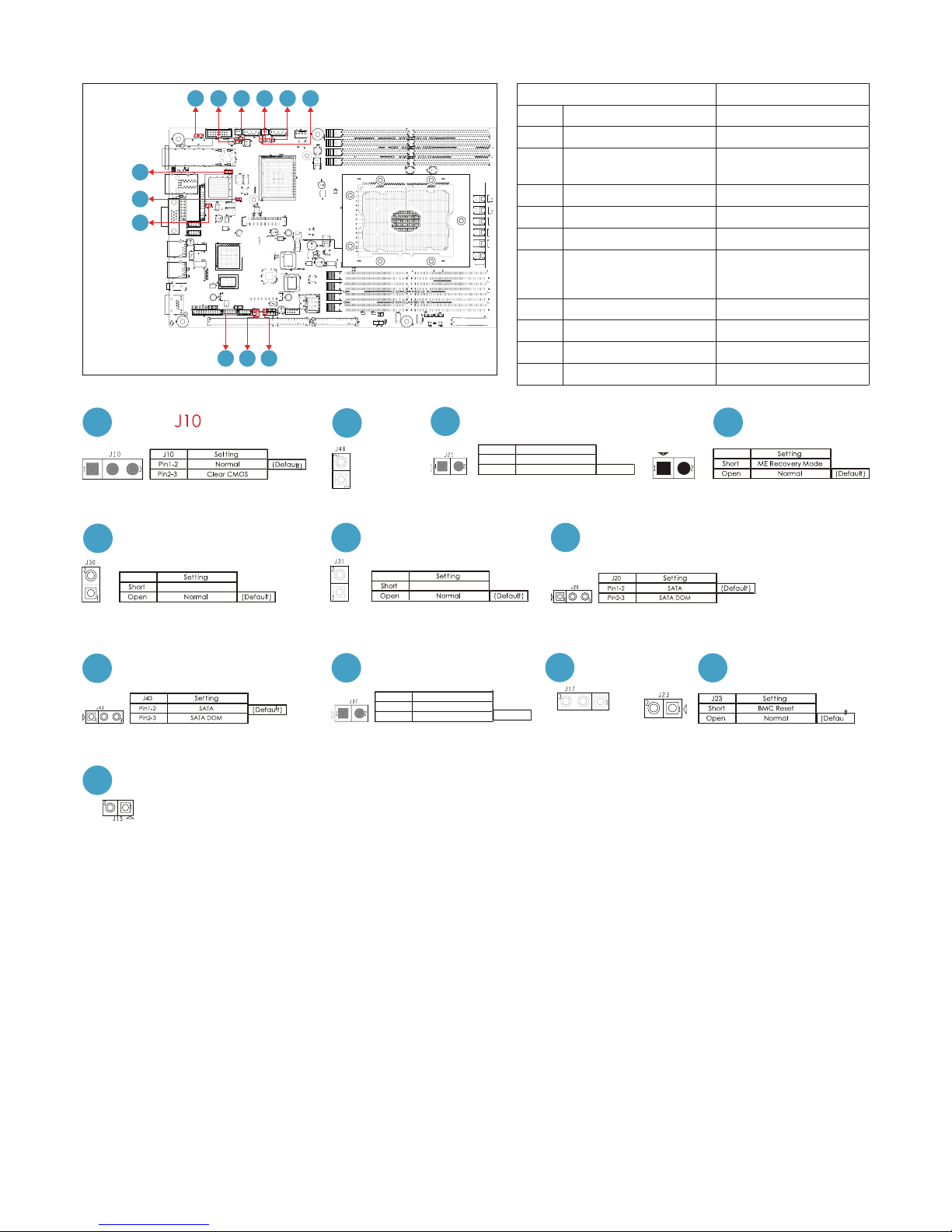
Connectors Location Connectors Location
1 Power Supply J87: 12V & 5VSB
6A per pin. 23 ME Recovery
Mode J35
2 Power Supply J86: 12V 24 AIC OPEN RACK
Header J40
3a
3b Serial ATA J33, J34 25 FAN Front J39
4 Serial ATA J32 26 MDI PHY Front J85
5 Front Panel J81 27a
27b SATA-DOM Power J22, J42
6VGA J7 28 LCM J9
7 COM1 J11 29 SGPIO J18
8 COM4 J12 30 SSGPIO J27
9 Front USB 3.0 J16 31 BMC Disable J30
10 Front USB 2.0 J49 32 Password Clear J31
11 DIMM Slots J56~J58, J61~J65,
J69~J76 33 PECI J44
12 CPU Sockets U55, U78 34 VRM SMB J24
13 Debug Port J13 35 All Node OFF J52
14 BMC Debug Port J14 36 PMBUS J45
15 Clear CMOS J10 37 BMC FAN J51
16 BMC IPMB J36 38a
38b SATA DOM Set Up J20, J43
17 Battery Socket BAT1 39 BIOS Recovery
Mode J37
18 Intruder J47 40 UART J17
19 SPI ROM Socket U25 41 BMC RESET J23
20 BMC ROM Socket U29 42 UID LED J15
21 Speaker J48 43 PCIE Hot-Plug
SMB (CPU0) J2001
22 FLASH Security
override J21 44 PCIE Hot-Plug
SMB (CPU1) J2002
3.3 Motherboard Content List

44
Chapter 3 Motherboard Settings
SB405-PV User's Manual
3.4 Internal Connectors/Jumpers
Connectors Location
6VGA J7
7 COM1 J11
8 COM4 J12
13 Debug Port J13
14 BMC Debug Port J14
GND
GND
AVSYNCO
NC
GND
DDC_DATAO
DACGO
GND
DDC_CLKO
GND
VGA_5V
AHSYNCO
DACBO
GND
NC
DACRO
J7
GND
KEY
P5V
PCH_IO2
PCH_IO1
GND
SMB_PCH_SDA
ESPI_CS1
PCH_CLKRUN
ESPI_ALERT0
KEY
P3V3
ESPI_PME
ESPI_SEL
CLK_DP80
PCH_CS0_N
RST_PERST_N
PCH_ IO3
P3V3
PCH _IO0
SMB_PCH_SCL
P3V3_AUX
GND
ESPI_RESET
KEY
ESPI_ALERT1
ESPI_SMI
P5V_AUX
J13
DSR
RTS
CTS
RI
NC
DCD
RXD
TXD
DTR
GND
J12
DSR
RTS
CTS
RI
NC
DCD
RXD
TXD
DTR
GND
J11
TXD
RXD
GND
J14
13
68
7
14
13
6
8
7
14

45
Chapter 3 Motherboard Settings
SB405-PV User's Manual
Connectors Location
10 Front USB 2.0 J49
14 BMC Debug Port J14
16 BMC IPMB J36
25 FAN Front J39
28 LCM J9
29 SGPIO J18
30 SSGPIO J27
34 VRM SMB J24
43 PCIE Hot-Plug SMB
(CPU0) J2001
44 PCIE Hot-Plug SMB
(CPU1) J2002
GND
COM_OUT_RXD4
COM_OUT_TXD4
FP_RSTBTN_N
FP_PWRBTN_N
J9
FM_SGPIO0_I2C_A0
FM_SGPIO0_I2C_A1
I2C14SCL
I2C14SDA
GND
P3V3_AUX
SGPIO_SATA0_DATA1
SGPIO_SATA0_DATA0
SGPIO_SATA0_LOAD
SGPIO_SATA0_CLOCK
J18
J18
28 29
14
28
25 29 30 16 10 44 43
34
GND
FAN_PWM5
FAN_PWM4
FAN_PWM3
FAN_TACH11
FAN_TACH10
FAN_TACH9
FAN_TACH8
FAN_TACH7
FAN_TACH6
I2CSCL
GND
GND
FAN_PWM2
FAN_PWM1
FAN_PWM0
FAN_TACH5
FAN_TACH4
FAN_TACH3
FAN_TACH2
FAN_TACH1
FAN_TACH0
I2CSDA
+3.3V_DUAL
J39
25
GND
SMB_PEHPCPU1_DA
T
SMB_PEHPCPU1_SCL
J2002
GND
SMB_PEHPCPU0_DA
T
SMB_PEHPCPU0_SCL
J2001
J24
SMB_VR_SCL
GND
SMB_VR_SDA
J24
34
44
43
KEY
GND
USB2_P6
USB2_N6
VDD_USB_P56
GND
GND
USB2_P5
USB2_N5
VDD_USB_P56
J49
10
I2C1SDA
GND
I2C1SCL
NC
J36
16
J14
GND
RXD
TXD
J14
14
FM_SGPIO1_I2C_A0
FM_SGPIO1_I2C_A1
I2C14SCL
I2C14SDA
GND
P3V3_AUX
SGPIO_SSATA0_DATA1
SGPIO_SSATA0_DATA0
SGPIO_SSATA0_LOAD
SGPIO_SSATA0_CLOCK
J27
30

46
Chapter 3 Motherboard Settings
SB405-PV User's Manual
Connectors Location
9 Front USB 3.0 J16
18 Intruder J47
37 BMC FAN J51
GND
INTRUDER
J47
J16
VDD_USB_P34
USB3_RX_N2
USB3_RX_P2
GND
USB3_TX_N2
USB3_TX_P2
GND
USB2_N2
USB2_P2
PCH_USB_OC#2 3
KEY
VDD_USB_P34
USB3_RX_N3
USB3_RX_P3
GND
USB3_TX_N3
USB3_TX_P3
GND
USB2_N3
USB2_P3
J51
GND
P12V
TACH
PWM
18
18 93 7
937

47
Chapter 3 Motherboard Settings
SB405-PV User's Manual
Connectors Location
1 Power Supply J87:12V & 5VSB 6A
per pin.
2 Power Supply J86:12V
5 Front Panel J81
24 AIC OPEN RACK
Header J40
26 MDI PHY Front J85
CHASSIS_1U2N_N
BNC_GPIO_EXIN
FAN_TACH1
FAN_PWM1
GND
FAN_TACH0
FAN_PWM0
GND
I2C8SDA
I2C8SCL
GND
INTRUDER_N
PMBUS_ALERT_N
PMBUS_DATA
PMBUS_CLK
GND
I2C1SDA
I2C1SCL
GND
BMC_RESET_N
J40
GND
GND
GND
GND
GND
GND
PS_ON#
J87
+12V
+12V
+12V
+12V
+12V
+5V_AUX
POWER OK
GND
GND
GND
GND
J86
+12V
+12V
+12V
+12V
MDI1_DATA_R_N
MDI1_DATA_R_P
MDI0_DATA_R_N
MDI0_DATA_R_P
MDI3_DATA_R_N
MDI3_DATA_R_P
MDI2_DATA_R_N
MDI2_DATA_R_P
J85
NMI_BTN
NC
UID_BTN
GND
RST_BTN
GND
PWR_BTN
HD_LED-
HD_LED+
PWR_LED-
KEY
PWR_LED
LAN2_ACT -
LAN2_ACT +
INTRUDER_N
I2CCL
I2CDA
LAN1_ACT -
LAN1_ACT +
FAUL_TLED
FAUL_TLED+
UID_LED -
UID_LED +
+3.3V_DUAL
J81
5
12
26
24
24
5
1
26
2

48
Chapter 3 Motherboard Settings
SB405-PV User's Manual
Connectors Location
15 Clear CMOS J10
21 Speaker J48
22 FLASH Security
override J21
23 ME Recovery Mode J35
31 BMC Disable J30
32 Password Clear J31
38a
38b SATA DOM Set Up J20, J43
39 BIOS Recovery Mode J37
40 UART J17
41 BMC RESET J23
42 UID LED J15
J31
J30
J15
P5V_AU
X
UID_LED
UART_TX
GND
UART_RX
J17
(Default)
J37
Short BIOS Recovery Mode
Setting
NormalOpen
J37
J43 J23
42
40
41
40
15
39
38 b
41
42
31 32 21
15 22
a
38 39
b
38 23
J48
+5V
SPEAKER
21
(Default)
J21
Short FLASH Security override
Normal
Setting
Open
J21
22 J35
J35
23
J30
J30
BMC Disable
31 J31
J31
Password Clear
32 J20
38 a

49
Chapter 3 Motherboard Settings
SB405-PV User's Manual
3.5.1 Front Panel LED Definition
Power
Yellow System is On
Blinking System is in Standby; System is off, but
has AC power
Off System has no AC power
UID Blue UID activity detected
Off No UID activity detected
System Fault Red
Critical system failure detected
(processors, memory, voltage
regulators, thermal events,fan failures,
NMI, etc)
Off No critical failures detected
Hard Disk Green (Blinking) Disk activity detected
Off No disk activity detected
LAN1_TRAFFIC Green (Blinking) LAN1 activity detected
Off LAN1 is not active
LAN2_TRAFFIC Green (Blinking) LAN2 activity detected
Off LAN2 is not active
3.5 LEDs

50
Chapter 3 Motherboard Settings
SB405-PV User's Manual
3.5.2 Rear I350 LAN LEDs
The NIC Port LED should be connected to Vaux (standby) voltage.
Description Left LED (LED4, LED2,)
(Link/Activity)
Right LED (LED3, LED1,)
(Speed)
No Link OFF OFF
Linked at 10 Mbps Link Green OFF
Active Blinking Green OFF
Linked at 100 Mbps Link Green Green
Active Blinking Green Green
Linked at 1000 Mbps Link Green Yellow
Active Blinking Green Yellow
LED1
LED3LED4
LED2

51
Chapter 3 Motherboard Settings
SB405-PV User's Manual
3.5.3 SFP+ LEDs
SFP+ LED Definition
LED5
Green LAN1 activity detected
OFF LAN1 is not active
LED7
Yellow (Blinking) LAN1 Link detected
OFF LAN1 is not Link
LED6
Green LAN0 Link detected
OFF LAN0 is not Link
LED4
Yellow (Blinking) LAN0 activity detected
OFF LAN0 is not active
LED7 LED6
LED4LED5

52
Chapter 3 Motherboard Settings
SB405-PV User's Manual
3.5.4 BMC LAN LEDs
BMC LAN LED Definition
LED1
ON UID activity detected
OFF UID is not active
LED2
ON BMC Rack LAN activity detected
(Only for Rack)
OFF BMC Rack LAN is not active
(Only for Rack)
LED3
ON BMC Rack LAN activity detected
(Only for Rack)
OFF BMC Rack LAN is not active
(Only for Rack)
LED18
Blinking BMC is working
OFF BMC not working
LED 2
LED 1
LED 3LED 3
LED 2
LED 1 LED 18
LED 18

53
Chapter 4 BIOS Configuration Settings
SB405-PV User's Manual
Chapter 4. BIOS Conguration Settings
Caution: When Quiet Boot IS enabled, OEM LOGO WILL BE displayed
INSTEAD OF POST MESSAGES.
There will be a message “Entering SETUP” displayed on the diagnostics screen.
Caution: For the official released version, the last digit of the
BIOS Version must end in an "0."
Press ESC to run the setup procedure.

54
Chapter 4 BIOS Configuration Settings
SB405-PV User's Manual
Step 1 Identify the BIOS Version.
Step 2 Load Optimal Default setting.
Step 3 Save the setting and exit the BIOS setup utility.

55
Chapter 4 BIOS Configuration Settings
SB405-PV User's Manual
4.1 Updating BIOS
Important Notes:
To identify the current BIOS version, please check the BIOS setup.

56
Chapter 4 BIOS Configuration Settings
SB405-PV User's Manual
Update BIOS by INSYDE H2OFFT-D utility under DOS environment
If you need to update Flash in the DOS environment, please use H2OFFT-D utility.
To use this utility, you must include the flash.bat , H2OFFT-D.exe, and bin file in the
same folder. Please follow the instructions to update whole flash part:
Execute flash.bat to update Flash in the DOS environment.
Reboot system.

57
Chapter 5 BMC Configuration Settings
SB405-PV User's Manual
Chapter 5. BMC Conguration Settings
Insert Ethernet LAN cable into the BMC LAN port. There are two methods to setup
BMC IP:
Step 1 BIOS SETUP Advanced H2O IPMI configuration BMC Configuration IPv4
source Static
BMC management port
5.1 Method 1 (Use the BIOS Setup)

58
Chapter 5 BMC Configuration Settings
SB405-PV User's Manual
Step 2 Type in the IP address. Set static IP.
Other manuals for SB405-PV
2
Table of contents
Other AIC Server manuals
Popular Server manuals by other brands

IBM
IBM SAN Volume Controller 2145-SV1 Hardware installation guide

VSCOM
VSCOM NetCom 111 Quick installation guide

Supero
Supero SUPERSERVER 5017C-LF user manual

Asus
Asus ESC4000-FDR G2S user guide

Moxa Technologies
Moxa Technologies NPort 5110 Series Quick installation guide

KEPCO
KEPCO IEPS 1000 Series Administrator's guide

HP
HP P5389A - Intel Pentium III-S 1.4 GHz Processor... installation guide

Lantronix
Lantronix EDS-MD EDS-MD4 Command reference

Supermicro
Supermicro AS -2024S-TR user manual

Pathos Acoustics
Pathos Acoustics Musiteca operating instructions

Intel
Intel SC450NX - Server Platform - 0 MB RAM Product guide

Supermicro
Supermicro X13SRA-TF Quick reference guide