Canon imagePRESS Server G200 User manual

Revision 1.1
imagePRESS Server G200
Service Manual

Introduction
Important Notices
Application
This manual has been issued by Canon Inc. for qualified persons to learn technical theory, installation, maintenance, and repair
of products.
This manual covers all localities where the products are sold. For this reason, there may be information in this manual that does
not apply to your locality.
Corrections
This manual may contain technical inaccuracies or typographical errors due to improvements or changes in products.
When changes occur in applicable products or in the contents of this manual, Canon will release technical information as the
need arises. In the event of major changes in the contents of this manual over a long or short period, Canon will issue a new
edition of this manual.
The following paragraph does not apply to any countries where such provisions are inconsistent with local law.
Trademarks
The product names and company names used in this manual are the registered trademarks of the individual companies.
Copyright
The copyright of this document belongs to Canon Inc. This document may not be copied, reproduced or translated into another
language, in whole or in part, without the prior consent of Canon Inc.
Copyright CANON INC. 2018
Caution
Use of this manual should be strictly supervised to avoid disclosure of confidential information.
Explanation of Symbols
The following symbols are used throughout this Service Manual.
Symbols Explanation Symbols Explanation
Check.
1x
Remove the claw.
Check visually.
1x
Insert the claw.
Check a sound. Push the part.
Introduction

Symbols Explanation Symbols Explanation
1x
Disconnect the connector. Connect the power cable.
1x
Connect the connector. Disconnect the power cable.
1x
Remove the cable/wire from the
cable guide or wire saddle.
Turn on the power.
1x
Install the cable/wire to the cable
guide or wire saddle.
Turn off the power.
1x
Remove the screw.
1x
Loosen the screw.
1x
Install the screw.
1x
Tighten the screw.
Cleaning is needed. Measurement is needed.
The following rules apply throughout this Service Manual:
1. Each chapter contains sections explaining the purpose of specific functions and the relationship between electrical and
mechanical systems with reference to the timing of operation.
In the diagrams, represents the path of mechanical drive; where a signal name accompanies the symbol, the arrow
indicates the direction of the electric signal.
The expression "turn on the power" means flipping on the power switch, closing the front door, and closing the delivery unit
door, which results in supplying the machine with power.
2. In the digital circuits, '1' is used to indicate that the voltage level of a given signal is "High", while '0' is used to indicate "Low".
(The voltage value, however, differs from circuit to circuit.) In addition, the asterisk (*) as in "DRMD*" indicates that the DRMD
signal goes on when '0'.
In practically all cases, the internal mechanisms of a microprocessor cannot be checked in the field. Therefore, the operations
of the microprocessors used in the machines are not discussed: they are explained in terms of from sensors to the input of
the DC controller PCB and from the output of the DC controller PCB to the loads.
The descriptions in this Service Manual are subject to change without notice for product improvement or other purposes, and
major changes will be communicated in the form of Service Information bulletins.
All service persons are expected to have a good understanding of the contents of this Service Manual and all relevant Service
Information bulletins and be able to identify and isolate faults in the machine.
Introduction

Contents
1. Introduction...................................................................................................... 1
Introduction..........................................................................................................................................2
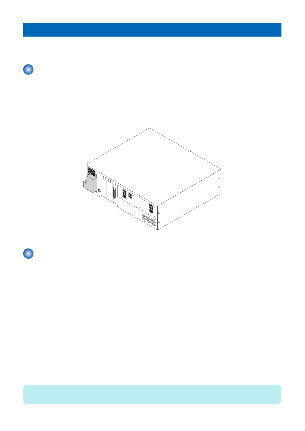
About the imagePRESS Server..............................................................................................................2
About this document..............................................................................................................................2
How the imagePRESS Server operates..................................................................................................3
Preparing for hardware installation or parts replacement..........................................................................3
Precautions ......................................................................................................................................... 3
Tools you will need................................................................................................................................5
2. USING THE IMAGEPRESS SERVER...............................................................6
Using the imagePRESS Server...........................................................................................................7
Starting, shutting down, rebooting, and restarting the imagePRESS Server.............................................. 7
3. REPLACING PARTS.........................................................................................9
Replacing Parts.................................................................................................................................10
Overview............................................................................................................................................ 10
imagePRESS Server components........................................................................................................10
imagePRESS Server connector panel and LED diagnostic codes...........................................................11
Accessing the imagePRESS Server..................................................................................................... 13
Checking imagePRESS Server internal connections..............................................................................14
Removing and replacing imagePRESS Server components...................................................................15
DIMM................................................................................................................................................. 17
Motherboard....................................................................................................................................... 18
Replacing the motherboard..................................................................................................................23
CPU and CPU cooling assembly.......................................................................................................... 24
Service board..................................................................................................................................... 28
Chassis fan.........................................................................................................................................28
Power supply...................................................................................................................................... 30
Hard disk drive (HDD)......................................................................................................................... 32
Restoring imagePRESS Server functionality after service...................................................................... 34
Cleaning the imagePRESS Server....................................................................................................36
4. INSTALLING SYSTEM SOFTWARE.............................................................. 37
Installing System Software................................................................................................................38
System software installation reminders.................................................................................................38
Backing up and restoring the system configuration................................................................................ 38
Using Fiery System Restore.................................................................................................................40
To create a backup..............................................................................................................................42
To restore from the backup image........................................................................................................ 42
To restore the system by booting from a bootable USB flash drive..........................................................42
Installing system software using a USB flash drive................................................................................ 42
Printing the Configuration pages.......................................................................................................... 46
Contents
i

5. TROUBLESHOOTING.....................................................................................47
Troubleshooting.................................................................................................................................48
Troubleshooting process......................................................................................................................48
6. SPECIFICATIONS........................................................................................... 60
Specifications.................................................................................................................................... 61
Hardware features...............................................................................................................................61
Physical specifications.........................................................................................................................61
Networking and connectivity.................................................................................................................61
Safety and emissions compliance.........................................................................................................61
7. INSTALLATION PROCEDURE.......................................................................63
How to Utilize This Installation Procedure.........................................................................................64
Symbols............................................................................................................................................. 64
Before Connection.............................................................................................................................65
Version of the host machine.................................................................................................................65
Installing the License...........................................................................................................................65
The IP addresses for communication between the host machine and server are set automatically............65
Check Item When Turning OFF the Main Power....................................................................................65
Check When Connecting the Power Plug to an Outlet........................................................................... 65
Securing Space for Installation.............................................................................................................65
Checking the Contents........................................................................................................................ 65
Installation Outline Drawing................................................................................................................. 66
Installation Procedure........................................................................................................................67
Installing the Open I/F PCB..................................................................................................................67
Installing the imagePRESS Server....................................................................................................... 69
Settings After Installation...................................................................................................................75
Setting of the Display Range of the Web Browser..................................................................................75
Settings After Installation..................................................................................................................... 75
Checking the Operation After Making the Settings.................................................................................76
Connecting to the Network...................................................................................................................77
Executing Image Quality Adjustment.................................................................................................... 77
Contents
ii

Introduction
This document includes information about servicing the Canon imagePRESS Server G200. In this document, Canon
imagePRESS Server G200 is referred to as “the imagePRESS Server.”
About the imagePRESS Server
The imagePRESS Server embeds computer connectivity and highly efficient PostScript and PCL printing capacity into the
imagePRESS C850/C750/C650/C65.
It allows the customer to use the printer as a PostScript printer and scanner, and it provides efficient image processing and printing
controls. Once it is connected to the printer through a network, customers can print to the imagePRESS Server from supported
client computers on the network (Windows or Mac, or a UNIX workstation running TCP/IP).
The imagePRESS Server ships with system software pre-installed so that customers can use the imagePRESS Server
immediately. However, as part of servicing the imagePRESS Server, you may need to reinstall system software.
imagePRESS Server
About this document
This service document describes how to install imagePRESS Server system software, and how to service the imagePRESS
Server hardware. It is not intended for customer use. Information about the printer, network, remote computers, software
applications, and imagePRESS Server operating system is not included in this document.
Illustrations
In this document, illustrations reflect the version of the imagePRESS Server being shipped at the time of publication. Components
in illustrations are subject to change. For information about imagePRESS Server components that do not match illustrations in
this document, contact your authorized service/support center.
Terms
In this document, the following terms are used.
•Replace: Refers to reinstallation of existing components. Do not install new components unless necessary.
•Printer touch panel: Refers to the printer user interface that is used to run the Fiery setup.
•Linux: This is the operating system of the imagePRESS Server. Available on System Software DVD.
•System software: The software installed on the hard disk drive (HDD) of the imagePRESS Server. Includes Linux operating
system software.
•Server software: The imagePRESS Server software. Runs on Linux operating system. Available on System Software DVD.
Document conventions
NOTE:
The Note: indicator highlights important messages and additional information.
1. Introduction
2

WARNING:
Warning: A warning concerning operations that may lead to death or injury to persons if not performed correctly. To use
the equipment safely, always pay attention to these warnings.
CAUTION:
Caution: A caution concerning operations that may lead to injury to persons if not performed correctly. To use the equipment
safely, always pay attention to these cautions.
IMPORTANT:
Important: Operational requirements and restrictions. Be sure to read these items carefully to operate the equipment
correctly, and avoid damage to the equipment or property.
How the imagePRESS Server operates
When a customer prints, the motherboard and printer interface board process image data. The printer interface board is a custom
board and allows the imagePRESS Server to communicate with the printer. The CPU, which is located on the motherboard,
controls the transfer of image data to and from the motherboard and runs the interpreter. DIMMs, which are also located on the
motherboard, hold image data during printing.
The interpreter rasterizes the page description file and compresses the image pattern into memory using compression technology.
The interpreter outputs the compressed raster data through the image frame buffer memory to the printer interface board. The
raster data is sent to the printer, which then renders the image on paper at maximum speed.
Preparing for hardware installation or parts replacement
Before installing or servicing the imagePRESS Server, follow general precautions and obtain the correct tools.
It is strongly recommended that before you service the imagePRESS Server, you carefully read all precautions and notices (see
“Precautions ” on page 3).
Also, keep in mind that the most common cause of a hardware problem is a faulty or loose connection. Before you replace an
expensive component, check internal and external connections (see “Checking imagePRESS Server internal connections” on
page 14).
Precautions
This section includes information about how to safely operate and service the imagePRESS Server and how to avoid damage to
imagePRESS Server components.
Report shipping damage
If there is evidence of shipping damage, save the shipping boxes and damaged parts. Call the shipper immediately to file a claim
and notify your authorized service/support center.
Do not change an existing network
The imagePRESS Server is probably connected to an existing Local Area Network (LAN) based on Ethernet hardware. The
network is the link between the customer’s computer, existing laser printers, and other prepress equipment. Never disturb the
LAN by breaking or making a network connection, altering termination, installing or removing networking hardware or software,
or shutting down networked devices without the knowledge and express permission of the site administrator.
Do not assign an IP address to the imagePRESS Server
Only the site administrator should assign an IP address to a network device, including the imagePRESS Server. If you enter an
incorrect IP address for the imagePRESS Server, errors may occur on connected devices.
Handling boards
When handling a printed circuit board, do not bend it. Hold it by opposing edges, rather than by the corners.
1. Introduction
3

Handling the hard disk drive
To ensure that you do not damage the hard disk drive, do the following:
• Follow electrostatic discharge (ESD) precautions.
• Keep magnets and magnetic-sensitive objects away from the hard disk drive.
• Do not loosen or remove the screws on the top of the hard disk drive. Doing so voids the warranty.
• Handle the hard disk drive by its sides and avoid touching the printed circuit board.
• Do not drop, jar, or bump the hard disk drive.
• Before you remove or install a hard disk drive, allow it to reach room temperature.
Avoid magnets
Keep magnets and magnetic-sensitive objects away from electronic components, especially the hard disk drive.
Electrostatic discharge
When you work with electronic components, electrostatic discharge is a concern since it can destroy circuits, or damage them,
reducing their life span. The area around the printer is most likely not static-free, and electrostatic discharge could occur.
Do the following to avoid damage due to electrostatic discharge:
• Work on a grounded antistatic mat.
• Wear an antistatic wristband, attached to the same location as the antistatic mat.
• Before you remove an electronic component from the shipping box, touch a metal area of the printer to discharge static from
your body.
• After you remove an electronic component from the shipping box, place it face up on a grounded antistatic surface.
• Leave electronic components in antistatic bags until you are ready to use them.
• Do not walk on carpet or vinyl while carrying an electronic component, unless it is in an antistatic bag.
• If you remove an electronic component from the printer, immediately place it in an antistatic bag.
Power cable
Observe the following guidelines:
• Only use the power cable that shipped with the imagePRESS Server or an appropriate replacement power cable. For
replacement parts, see your authorized service support center.
• Before you open the imagePRESS Server, unplug the imagePRESS Server.
• Keep the power cable away from foot traffic.
• Do not place objects on the power cable.
• Do not plug the imagePRESS Server into a 2-hole, ungrounded power outlet by means of a 3-prong adapter.
• Do not plug the imagePRESS Server into a circuit connected to heating or refrigeration equipment (including a water
dispenser).
• Do not plug the imagePRESS Server into a switchable power outlet.
• Do not pull the cable to unplug the imagePRESS Server. Instead, pull the plug.
• Do not tamper with or disable the power cable grounding plug.
• Do not use an extension cord.
Do not have liquids near the imagePRESS Server
If liquid spills on the imagePRESS Server, immediately unplug the imagePRESS Server.
Do not open the power supply
For more information about the power supply, see “Power supply” on “Power supply” on page 30.
Do not open the hard disk drive
For more information about the hard disk drive, see “Hard disk drive (HDD)” on “Hard disk drive (HDD)” on page 32.
Use caution with sharp edges
The edges of some imagePRESS Server components are sharp.
Fan notice
WARNING:
The imagePRESS Server contains hazardous moving parts. When servicing the imagePRESS Server, keep away from
moving fan blades.
1. Introduction
4

Tools you will need
To install or service the imagePRESS Server, you will need the following tools and parts:
• ESD wrist grounding strap and antistatic mat
• Flathead screwdriver
• #0, #1, and #2 Phillips head screwdrivers
• Needlenose pliers
• imagePRESS Server documentation, including the customer media pack and any related service bulletins
IMPORTANT:
Avoid touching magnetic tools to storage media such as hard disk drives. Contact between magnetic tools and magnetic
storage media may result in data corruption.
1. Introduction
5

Using the imagePRESS Server
This chapter describes how to use the imagePRESS Server.
Starting, shutting down, rebooting, and restarting the imagePRESS
Server
Always use the following procedures to start, shut down, reboot, or restart the imagePRESS Server.
IMPORTANT:
Always verify that the imagePRESS Server is not in use before you power off or restart it. Make sure that the system is not
processing or printing a job. Before you take the imagePRESS Server off the network, always obtain permission from the
network administrator.
To start the imagePRESS Server
1. Press the power switch to set ON (|).
Starting the imagePRESS Server
2. Power on the printer using the main power switch.
The imagePRESS Server will automatically turns on as the printer warms up.
If it has been enabled in Setup, the imagePRESS Server Start page will also print automatically when the imagePRESS Server
is ready for use.
NOTE:
If the imagePRESS Server does not start up within 10 minutes, see the Startup section of “Table 1: Causes and solutions when
printer does not print” on“If the printer does not print” on page 56
To shut down the imagePRESS Server
1. Make sure that the imagePRESS Server is not receiving, processing, or printing any jobs.
2. Make sure that the printer is not in use.
3. Power off the printer using the main power switch on the front.
The imagePRESS Server will automatically start the shutdown process. Wait for the printer and the imagePRESS Server to
power off completely.
4. Move the imagePRESS Server power switch to the OFF (O) position.
To restart the imagePRESS Server
1. Make sure that the imagePRESS Server is not receiving, processing, or printing jobs.
2. From the printer control panel, press Main Menu button. If the Fiery icon does not appear on the copier touch panel, press
Show All.
3. From the printer touch panel, select Fiery > Tools > Restart Server.
2. USING THE IMAGEPRESS SERVER
7

The imagePRESS Server Tools menu
2. USING THE IMAGEPRESS SERVER
8

Replacing Parts
Generally, the imagePRESS Server does not require regular maintenance. Use the procedures in this chapter to inspect, remove,
reseat, or replace major hardware components.
Overview
This chapter includes information about the following:
• Diagrams of imagePRESS Server components(“imagePRESS Server components” on page 10)
• Connector panel and LED display codes (“imagePRESS Server connector panel and LED diagnostic codes” on page 11)
• Accessing the imagePRESS Server (“To access the imagePRESS Server” on page 13)
• Cable connections (“Checking imagePRESS Server internal connections” on page 14)
• Removing and replacing imagePRESS Server components (“Removing and replacing imagePRESS Server components”
on page 15)
IMPORTANT:
When performing the procedures described in this chapter, see“Precautions ” on page 3and“Tools you will need” on page
5
imagePRESS Server components
The figures in this section provide an overview of components in the imagePRESS Server.
3. REPLACING PARTS
10

4
1
8
5
13
16
19
6
14
12 17
3
18
2
10
11
7
9
15
20
Exploded view of imagePRESS Server components
No. Item No. Item No. Item No. Item
1 Chassis cover 7 Battery 12 Chassis fan guard 18 Power switch
2 Printer interface board 8 Motherboard 13 Service board 19 Chassis
3 CPU cooling assembly 9 500GB SATA HDD
(hard disk drive)
14 HDD SATA data cable 20 Power supply duct
4 4GB DIMM 15 10-pin power button cable
5 3.3GHz CPU 10 HDD bracket 16 Service board cable
6 Security chip 11 Chassis fan 17 Power supply
imagePRESS Server connector panel and LED diagnostic codes
The connector panel of the imagePRESS Server has the external connectors and power switch. Familiarize yourself with the
connector panel of the imagePRESS Server.
3. REPLACING PARTS
11

1
3
4
5
6
7
8
9
2
imagePRESS Server connector panel
No. Item No. Item
1 Type A USB 2.0 ports (x2) 6 Network port (Upper RJ-45)
2 Type A USB2.0 ports (x2) 7 Crossover Ethernet connector
3 Type A USB3.0 ports (x2) 8 Duct
4 Printer interface connector 9 Power switch
5 Power connector
During startup, the imagePRESS Server advances through a standard diagnostic sequence. Each diagnostic code flashes rapidly
on the LED display during this sequence, until the imagePRESS Server reaches Idle. At Idle, the LED display shows the 00 code.
NOTE:
The LED display is mounted in upside-down orientation.
3. REPLACING PARTS
12

1 2
LED display
No. Item
1 Service switch
2 LED display
If the LED display hangs on a code other than 00, one or more diagnostic tests may have failed. Look up the diagnostic code in
“Table 1: Causes and solutions when printer does not print” on “If the printer does not print” on page 56 to determine the
troubleshooting actions that you should take.
Accessing the imagePRESS Server
Always use the following procedure to disconnect the imagePRESS Server from the printer and open the unit for inspection and
service.
IMPORTANT:
Make sure that you attach an ESD grounding wrist strap and follow standard ESD (electrostatic discharge) precautions
before following this procedure. For details, see“Precautions ” on page 3.
■ To access the imagePRESS Server
1. Make sure that the imagePRESS Server is not receiving, processing, or printing any jobs.
2. Make sure that the printer is not in use, and power off the printer using the main power switch on the front.
Wait for the printer and the imagePRESS Server to power off completely.
3. Move the imagePRESS Server power switch to the OFF (O) position.
4. Remove all external cables from the imagePRESS Server connectors.
5. Remove the imagePRESS Server from the printer.
For detailed information about removing/installing the printer, see “Installing the imagePRESS Server” on page 69.
6. Remove the two screws that secure the cover of the imagePRESS Server to the chassis (see Figure below ).
Set aside the screws so that you can replace them later.
7. Raise the cover and slide it toward the connector panel of the chassis to remove it.
Set aside the cover so that you can replace it later.
The imagePRESS Server internal components are now accessible.
3. REPLACING PARTS
13

Removing the chassis cover
Checking imagePRESS Server internal connections
The most common causes of problems are faulty and loose connections. Before you conclude that any internal component has
failed, remove, inspect, and reseat all appropriate connections, and then verify that the problem still occurs.
IMPORTANT:
Before you touch any parts inside the imagePRESS Server, attach a grounding wrist strap. Touching the chassis also
discharges static electricity.
■ To check cable connections
1. Access and open the imagePRESS Server (see “Accessing the imagePRESS Server” on page 13).
NOTE:
Refer the label behind the chassis cover.
2. Place the imagePRESS Server on a flat surface so that the internal components are facing up.
3. Make sure that the battery is properly installed (see “Battery” on page 18).
4. Inspect the HDD data cable to make sure that it is intact and connected to the SATA0 connector on the motherboard (see
“Motherboard jumpers” on page 19).
NOTE:
The imagePRESS Server will not boot up if the HDD data cable is connected to any other SATA connector on the motherboard.
Faulty data cables are easily overlooked. Check the contact point between the cable and the connector to ensure that they
have not separated. If a data cable is suspect, substitute it with a tested cable.
5. Check the fan cables of the chassis fan and CPU fan.
Make sure that the cables are intact.
6. Check the service board cable.
Make sure that the cable is intact and properly connected to the service board and the motherboard. For more information,
see “To replace the service board” on page 28.
7. Make sure that the internal power cables are intact and properly connected to the power supply, HDD, and motherboard.
8. Check the 10-pin power button cable that connects the printer interface board (J351) and the motherboard (J11). Make sure
that the cable is intact.
The following diagrams illustrate the internal cable connections between hardware components and the motherboard.
3. REPLACING PARTS
14

3
1a
6
1b
4
5
1c
2
A
B
C
D
imagePRESS Server internal cable connections
No. Item No. Item
A HDD C Chassis fan
B Power supply D CPU fan
No. Cable key From To
1 Power supply cables Power supply a. SATA power connector-HDD
b. 4-pin motherboard connector (PWRCONN1)
c. 24-pin motherboard connector (J24)
2 10-pin power button cable Printer interface board (J351) J11 connector on motherboard
3 HDD data cable HDD data connector SATA0 on motherboard
4 Service board cable Service board connector EFI GPIO Header connector on motherboard (J4)
5 CPU fan cable CPU fan CPUFAN connector on motherboard (CPU FAN J16)
6 Chassis fan cable Chassis fan FRONT FAN connector on motherboard (J30)
Removing and replacing imagePRESS Server components
Before replacing costly components, be sure to verify the connections between the printer and the imagePRESS Server. Also,
verify the connections of each replaceable imagePRESS Server component. For more information about troubleshooting, see
“Troubleshooting” on page 48.
The following sections describe how to remove and install replaceable parts on the imagePRESS Server:
• Printer interface board
• DIMM
• Battery
• Motherboard
• CPU and CPU cooling assembly
• Service board
• Chassis fan
• Power supply
• Hard disk drive (HDD)
For information about replacing other components, see the documentation that accompanies your printer.
3. REPLACING PARTS
15
Other manuals for imagePRESS Server G200
1
Table of contents
Other Canon Server manuals

Canon
Canon imagePRESS Server G250 V2 User manual

Canon
Canon imagePRESS Server M10 User manual

Canon
Canon VB101 User manual

Canon
Canon ImagePRESS Server H350 V2 User manual

Canon
Canon imagePRESS Server G200 Quick guide

Canon
Canon ColorPass-Z7400 User manual

Canon
Canon P 400 User manual

Canon
Canon VB150 User manual

Canon
Canon imagePRESS A3200 Installation and maintenance instructions

Canon
Canon VB101 User manual