Syris v300TM User manual

Gebruikershandleiding (Dutch)
v300™/v600™ Visualisatiesysteem
Manuel d’Utilisation (French)
Système de visualisation v300™/v600™
Benutzerhandbuch (German)
v300™/v600™ Visualisierungssystem
Manuale del Proprietario (Italian)
v300™/v600™ Sistema di Visualizzazione
Manual del Propierario (Spanish)
Sistema de Visualización Serie v300™/v600™
Doc #5002
Revision 3 (July 2004)
v300TM/v600TM Visualization System
International Owner’s Manual

Revision 3 (July 2004) English
v300TM/v600TM Visualization System
Owner’s Manual

2 www.syrisscientific.com
Syris Scientific, LLC
Contact Information
Manufacturer
Syris Scientific, LLC
22 Shaker Road
Gray, Maine, USA 04039
Phone: 207.657.7050
Fax: 207.657.7051
Email: techsupport@syrisscientific.com
Web: www.syrisscientific.com
Service Center Hours:
Monday – Friday
8:00AM – 5:00PM US Eastern Time
Authorized European Representative
CEpartner4U BV
Esdoornlaan 13,
3951DB Maarn
The Netherlands
Phone: +31 (0)343.442.524
Cell: +31 (0)6.516.536.26
Fax: +31 (0)343.442.162
Email: offi[email protected]
Contact: Theo Nusselder / Harry Teirlinck

v300/v600 Owner’s Manual
Doc #5002 (English) 07/2004 3
Introduction
Thank you for purchasing the Syris Scientific v300/v600 Visualization System.
This unique, patented Visualization System is the result of many years of research,
development, testing, and field application. You will enjoy many years of procedural
benefits by following the care and use instruction provided in this manual. Please do
not hesitate to call our service group at 800.714.1374 or 207.657.7050 if we can
be of any assistance in the use of your new system.
Syris Scientific, LLC
Table of Contents
Legend 4
Safety Warnings and Hazards 5
Product Description 6
Product Setup 8
Product Operation 10
Illuminator Replacement 11
Handling, Cleaning, and Storage 14
General Specifications 15
Parts/Accessories List 15
Warranty Information 16
Warranty Registration Card 19

4 www.syrisscientific.com
Syris Scientific, LLC
Legend
The following symbols can be found on components of the v300 and v600
Visualization Systems.
Symbol Title Definition
Attention! Consult accompanying
documents
Dangerous Voltage! Warning, dangerous
voltage present
CE Conformity Mark
Product conforms to the
requirements of applicable
EU directives
On
Off
Direct Current (DC)
Alternating Current (AC)
Volts Direct Current
Amperes

v300/v600 Owner’s Manual
Doc #5002 (English) 07/2004 5
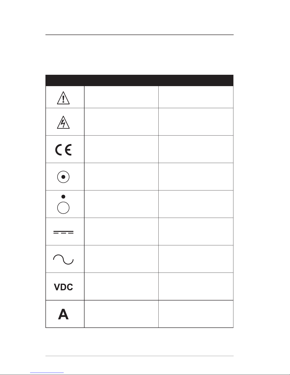
Safety Warnings and Hazards!
General Hazards
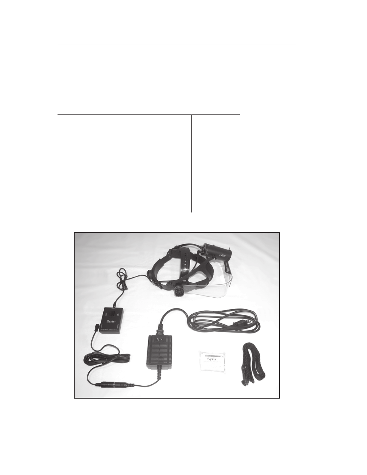
Only individuals familiar with the operation and safe use of this system should
operate it.
Keep the system out of reach of children.
Do not walk on or wheel objects over cables and cords.
Do not overextend the cables and cords to prevent premature wear.
Do not drop any component of the system. Physical shock may cause
permanent damage.
Do not clean the components of the system with abrasives or solvents.
Do not autoclave any component of the system.
Do not insert objects into any opening of a component of the system.
Do not direct light from the Illuminator Module at the eyes of anyone, or look
into the Illuminator Module while it is on.
Do not use the system as a light to navigate your environment.
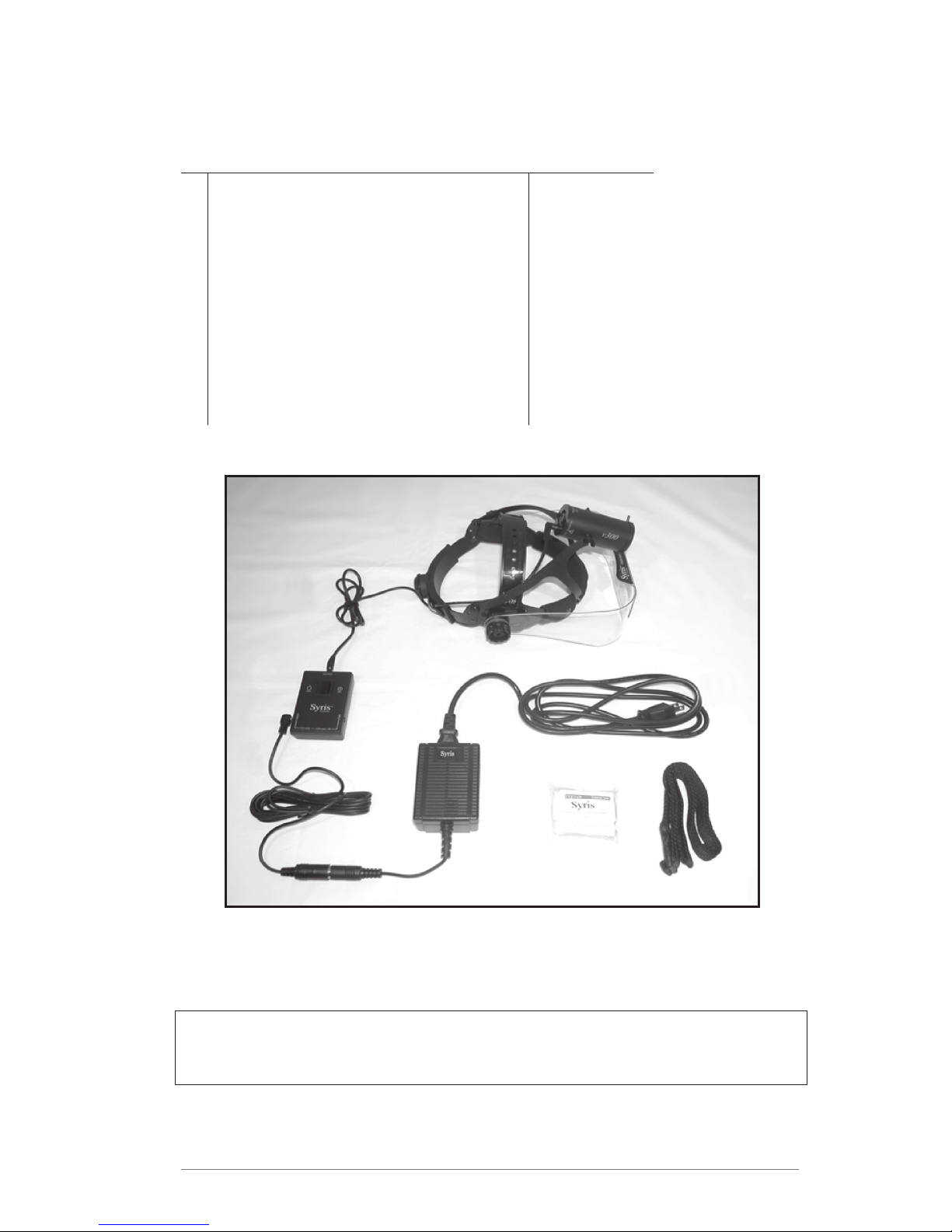
Electrical Hazards
Never immerse any component of the system in water or other liquids.
Use only an approved, grounded outlet.
Do not allow metal objects or body parts to touch electrical connections.
Do not use any other power supply with this system. Damage resulting from
use of a power supply other than the Power Supply Module voids the warranty.
Always use the Power Control Module when using your system. The system
is intended to function with the module to provide a safety interface between
the user and the power supply.
Unplug the Power Supply Module when connecting or disconnecting cables to
any component of the system.
Fire Hazards
Do not operate the system in a flammable or explosive atmosphere.
Do not block any opening of the system. Doing so may cause overheating of
the Illuminator Module.
Avoid operating the system in dusty environments.
•
•
•
•
•
•
•
•
•
•
•
•
•
•
•
•
•
•
•

6 www.syrisscientific.com
Syris Scientific, LLC
Product Description
This Owners Manual applies to the v300 and v600 Visualization Systems.
A diagram and list of the components of each system are presented here.
v300 Visualization System (Figure 1)
Components Part Number
1 v300 Headgear Z2001-00
v300 Illuminator Z2074-00
2 Upper DC Power Cable Z1762-00
3 Power Control Module Z2076-00
4 Lower DC Power Cable Z2079-00
5 Power Supply Z2077-00
6 AC Power Cable
7 Power Control Module Belt Z1763-00
8 Lens Wipes
Figure 1. v300 Visualization System Components
1
2
3
4
5
6
7
8

v300/v600 Owner’s Manual
Doc #5002 (English) 07/2004 7
v600 Visualization System (Figure 2)
Components Part Number
1 v600 Headgear Z1924-00
v600 Illuminator Z2073-00
2 Upper DC Power Cable Z1762-00
3 Power Control Module Z2076-00
4 Lower DC Power Cable Z2079-00
5 Power Supply Z2077-00
6 AC Power Cable
7 Power Control Module Belt Z1763-00
8 Lens Wipes
IMPORTANT! Syris Scientific is not responsible for any damage that may have
resulted from shipping. Should you find any damage to your system, please
call the shipping company immediately to fill out a claim.
Figure 2. v600 Visualization System Components
1
2
3
4
5
6
7
8

8 www.syrisscientific.com
Syris Scientific, LLC
Product Setup
The following procedures may be used to adjust the headband and complete the
wiring setup for either the v300 or v600 Visualization System.
Headband Adjustment (Figure 3)
1) Begin by adjusting the height of the top strap of the Headgear. This strap is
adjusted by separating the strap and sliding it to a new position. The strap is
secured by locking the plastic buttons on the lower strap into the holes of the
upper strap.
2) Loosen the Headgear headband by pushing the knob at the back of the
headband and turning it counter-clockwise.
3) Position the Headgear on your head, ensuring that the front of the headband
sits comfortably above your eyebrows. If the Headgear sits too high or two low
on your head, repeat step one.
4) Tighten the headband by pushing the knob at the back of the headband and
turning it clockwise.
5) Adjust the position of the Visi-Shield by turning the knobs on either side of the
Headgear. When properly positioned, the magnifying lens should be in your
normal line of sight.
6) It is critical that the top strap of the headgear be adjusted to allow the
rear section of the headgear to fit below the protuberance at the base
of your skull! The system will be extremely uncomfortable without this
adjustment! See Fig. 3 below.
Figure 3. v300/v600 Headgear Adjustment

v300/v600 Owner’s Manual
Doc #5002 (English) 07/2004 9
Wiring Setup (See Figures 1 or 2)
1) Plug the Upper DC Power Cable into the back of the Illuminator Module.
2) Plug the phone plug of the Upper DC Power Cable into either side of the Power
Control Module.
3) Plug the phone plug of the Lower DC Power Cable into the remaining side of
the Power Control Module.
4) Plug the female DIN connector of the Lower Power Cable into the male DIN
connector of the Power Supply.
5) Plug the IEC connector of the AC Power Cord into the IEC port on the Power
Supply.
6) Plug the AC plug of the AC Power Cord into an approved outlet.
After completing the wiring setup procedure, turn the switch of the Power Control
Module to on. You should immediately hear the fan of the Illuminator Module turn
on. To prevent shock to the Illuminator Module, the system is designed to gradually
turn on the Illuminator over a five second period.
IMPORTANT! If there is no evidence of the light or fan when you turn the
system on, immediately turn off the Power Control Module. Check the wiring
setup again.

10 www.syrisscientific.com
Syris Scientific, LLC
Product Operation
The v300/v600 Visualization System is intended to enhance the vision of medical
professionals when used in the patient environment during inspections and
procedures.
The v300/v600 Visualization System is designed to enhance the surface or the sub-
surface features of a patient’s skin. This is accomplished by parallel-polarizing or
cross-polarizing the light emitted from the Illuminator Module. To change between
surface and sub-surface viewing mode, use the following simple procedure:
1) While wearing the Headgear, locate the Illuminator Module with your free hand.
2) Slide your hand down the Illuminator Module until you locate the adjustment
peg located at the front of the barrel.
3) Gently grasp the adjustment peg and rotate it as shown in Figure 4.
4) As worn on the head, the surface (parallel-polarized) mode will be seen
when the adjustment peg is at the 10 o’clock position. The sub-surface
(crossed-polarized) mode will be seen when the adjustment peg is at the
2 o’clock position.
NOTE: In order to observe the effects of the system, the user must be looking
through the Visi-Shield
Figure 4. Polarization Adjustment
Sub-Surface Surface

v300/v600 Owner’s Manual
Doc #5002 (English) 07/2004 11
Illuminator Replacement
As with any intense illumination source, the v300/v600 Illuminator Module will wear
out with use. High output cooling of the Illuminator Module extends the expected
life to 400+ hours under normal conditions. Spare Illuminator Modules can be
purchased to enable the user to continue use with minimal interruption in the event
of an Illuminator Module failure. It is highly recommended that a spare Illuminator
Module be kept on hand.
Please use the following procedures to replace the Illuminator Module in either your
v300 or v600 Visualization System. If you have any questions, please contact our
service group at 800.714.1374 or 207.657.7050.
Illumination Condition Indicator
The v300/v600 Series is equipped with one of the most sophisticated diagnostic
systems of any lighting or vision system in the medical world. A powerful
microprocessor constantly monitors the entire system of the lighting and cooling to
ensure maximum performance. Part of this computer’s function set is a display of the
Illuminator Module’s (1 in Fig 1) condition. Three colored LED’s are installed to be
visible through the air outlet vents on the rear of the illuminator.
Green: Will remain visible for the first 75% of its life expectancy.
Yellow: Will indicate 5-24% of life expectancy remains. It is suggested to order
replacement at this point.
Red: Will indicate less than 5% of life expectancy remains. The bulb will alternate
dim and bright 7 times at startup during this critical stage showing that
the illuminator module has reached its life expectancy.
The LED’s flash a readout of the elapsed hours on the Illuminator Module 30 seconds
after the power is applied. The red LED flashes the number of hundreds of hours,
the yellow flashes the number of 10s of hours and the green flashes the number of
single hours, so 124 hours would be 1 red, 2 yellow and 4 green. This is followed
in another 15 seconds by a second series of flashes showing the number of on/off
cycles. This sequence differs from the first in that it is divided by 10, so 120 would be
1 yellow and 2 green flashes.
A typical life span for an Illuminator Module (1 in Fig 1) is in excess of 400
hours. Should your illuminator fail prior to 400 hours, a pro-rated warranty
will apply.

12 www.syrisscientific.com
Syris Scientific, LLC
v300 Illuminator Module Replacement
1) Turn off the v300 Visualization System and disconnect the AC Power Input
Cable from the wall outlet. Disconnect the Upper DC Power Cable from the
old Illuminator Module.
2) Allow the old Illuminator Module to cool at least ten minutes before
proceeding.
3) Loosen the plastic wing nuts on either side of the old Illuminator Module
approximately one turn, and remove it from the Headgear frame.
4) Install the new Illuminator Module on the Headgear frame and tighten the
plastic wing nuts.
5) Connect the Upper DC Power Cable to the Illuminator Module, and plug
AC Power Input Cable into a wall outlet.
6) Turn the system on and make sure the both the lamp and fan are functioning.

v300/v600 Owner’s Manual
Doc #5002 (English) 07/2004 13
v600 Illuminator Module Replacement
1) Turn off the v600 Visualization System and disconnect the AC Power Input
Cable from the wall outlet. Disconnect the Upper DC Power Cable from the
old Illuminator Module.
2) Allow the old Illuminator Module to cool at least ten minutes before
proceeding.
3) Remove the new Illuminator Module from the packing tube. Enclosed in the
packing tube is a cotton glove. Please use this glove for handling the new
Illuminator Module.
4) Remove the old Illuminator Module from the optics tube by rotating it counter-
clockwise as shown in Figure 5.
5) With a gloved hand, remove the new Illuminator Module from its plastic
wrapper.
IMPORTANT! Do not allow the Illuminator Module bulb or reflector to come
in contact with exposed skin or other foreign material. This may cause
premature failure of the Illuminator Module.
6) Install the new Illuminator Module in the optics tube by screwing it clockwise.
IMPORTANT! Do not force the new Illuminator Module into the optics tube.
If you are having difficulty installing the new Illuminator Module, rotate it
counter-clockwise one turn and then re-attempt to gently screw it into the
optics tube. Figure 5: Removal of v600 Illuminator Module.
7) Connect the Upper DC Power Cable to
the Illuminator Module, and plug AC
Power Input Cable into a wall outlet.
8) Turn the system on and make sure the
both the lamp and fan are functioning.
Figure 5. Removal of v600 Illuminator Module

14 www.syrisscientific.com
Syris Scientific, LLC
Handling, Cleaning, and Storage
To keep your v300/v600 Visualization System in optimum condition, please follow
the handling, cleaning, and storage guidelines.
Handling
To avoid scratching or smudging the Visi-Shield, handle the system by grasping
the headband.
The Upper and Lower DC Power Cords are built to be lightweight and are
therefore not armored. Use care when handling the power cords and ensure
that they are not pulled or pinched. Damaged cords may not be covered by the
limited product warranty.
Cleaning
Clean the system after every use that may have caused contamination.
Clean the entire product with approved disinfectant towelettes or towelettes
containing isopropyl alcohol.
Never clean any component of the system with hard or abrasive objects.
After cleaning the system, it is recommended that the Visi-Shield and magnifying
lenses be wiped with optical cloth or equivalent non-abrasive, non-linting cloth.
Never autoclave any component of the system.
Storage
To protect the system, it is suggested that it be stored in the box it was shipped in.
For short term storage, the Power Supply may remain plugged in, but the Power
Control Module should be turned off.
For long term storage, Power Supply should be unplugged.
•
•
•
•
•
•
•
•
•
•

v300/v600 Owner’s Manual
Doc #5002 (English) 07/2004 15
General Product Specifications
Shipping/Storage Dimensions
v300: 18 x 14 x 9 in (0,5 x 0,36 x 0,23 m)
v600: 23 x 13 x 10 in (0,58 x 0,33 x 0,25 m)
Shipping Weight
v300: 7 lb (3,1 kg)
v600: 8 lb (3,6 kg)
Power Supply
Input: 100-250 VAC, 50-60 Hz
Output: 13.8 VDC, 3 A maximum
Parts/Accessories List
Please contact Syris Scientific at 800.714.1374 or 207.657.7050 if you would
like to order any of the following parts or accessories for your v300 or v600
Visualization System.
Order Code Description
Z1924-00 v600 Visualization System
Z2001-00 v300 Visualization System
Z2073-00 v600 Illuminator Module Kit
Z2074-00 v300 Illuminator Module Kit
Z2075-00 Visi-Shield with 3 Diopter (1.75 X mag.) Lens
Z2076-00 Power Control Module
Z2077-00 v300/v600 Power Supply
Z2079-00 Lower DC Power Cable
Z2383-00 Black Headbands, one front-one rear
Z2095-00 3 Diopter (1.75 X mag.) Lens Set
Z2098-00 5 Diopter (2.25 X mag.) Lens Set
Z1762-00 Upper DC Power Cable
Z1763-00 Power Control Module Belt

16 www.syrisscientific.com
Syris Scientific, LLC
Warranty Information
Syris Scientific, LLC warrants this product to be free from defects in material and
workmanship, according to the following terms and conditions;
1) The limited warranty for the Product extends for one (1) year beginning on
the date of purchase of the product with the exception of the Illuminators
(Z2073-00 and Z2074-00). A typical life span for the Illuminator Module
is in excess of 400 hours. Should your illuminator fail prior to 400
hours, a prorated warranty will apply.
2) The limited warranty for the product extends only to the original consumer
purchaser (“Consumer”) of the product and is not transferable or assignable
to any subsequent purchaser or end user.
3) During the limited warranty period, Syris Scientific will repair or replace, at the
Company’s option, any defective parts, or any parts which will not properly
operate for their intended use with new or factory rebuild replacement items.
No charge will be made to the Consumer for any such parts, with exception of
the Illuminator Module. The Company will also pay the labor charges incurred
by Syris Scientific in repairing or replacing the defective parts. The external
housing and cosmetic parts shall be free of defects at the time of shipment
and, therefore, shall not be covered under these limited warranty terms.
4) Upon request from Syris Scientific, the Consumer must provide information to
reasonably prove the date of purchase.
5) The Consumer shall bear the cost of shipping and any duties to Syris Scientific
in Gray, Maine, USA. Syris Scientific shall bear the cost of shipping (but not
duties) the product back to the Consumer after completion of any service which
falls under the limited warranty.
6) The Consumer shall not have coverage of benefits under this warranty if any
of the following conditions are applicable:
a. The Product has been subject to: abnormal use, abnormal conditions,
improper storage, exposure to moisture or dampness, unauthorized
modifications, unauthorized connections, unauthorized repair, misuse,
neglect, abuse, accident, alteration, improper installation, or other acts
which are not the fault of Syris Scientific, including damage caused by
shipping and blown fuses.
b. Syris Scientific was not notified by the Consumer of the alleged defect
or malfunction of the product during the applicable warranty period.
c. The product serial number or date codes have been removed, defaced,
or altered.

v300/v600 Owner’s Manual
Doc #5002 (English) 07/2004 17
7) If a problem develops during the limited warranty period, the Consumer should
follow this procedure:
a. Call Syris Scientific at 800.714.1374 or 207.657.7050 to obtain a
Returned Material Authorization Number (RMA).
b. Write a brief description of the problem, and include the Consumer
daytime phone number, return address for shipping, proof of purchase,
and the RMA number.
c. Ship the product prepaid and insured to:
Syris Scientific
22 Shaker Road
P.O. Box 127
Gray, ME 04039
U.S.A
Attn: Service Department
8) The Consumer will be charged for any parts, labor and/or shipping charges
not covered by this limited warranty.
9) If the product is returned during the limited warranty period, but the problem
with the Product can not be fixed under the terms and conditions of this limited
warranty, the Consumer will be notified and given an estimate of the charges
the Consumer must pay to have the Product repaired. All shipping charges
will be billed to the Consumer. If the estimate is refused, the Product will be
returned freight collect. If the Product is returned to Syris Scientific after the
expiration of the warranty period, Syris Scientific normal service policies shall
apply and the Consumer will be invoiced for all shipping charges.
10) Any implied warranty of the merchantability or fitness for a particular purpose
or use, shall be limited to the duration of the foregoing written warranty.
Otherwise, the foregoing warranty is the Purchaser’s sole and exclusive remedy,
and in lieu of all other warranties, expressed or implied, Syris Scientific shall
not be liable of incidental or consequential damages or a loss of anticipated
benefits or profits resulting from the purchase or use of the Product, or arising
from the breach of the warranty even if Syris Scientific knew of the likelihood of
such damages.
11) Some states do not allow the limitation of how long an individual warranty
lasts, so the above limitations may not apply to the Consumer. Some states
do not allow the exclusion, or limitations or exclusions may not apply to the
Consumer. This warranty gives the Consumer specific legal rights and the
Consumer may also have other rights which vary from state to state.
12) Syris Scientific neither assumes nor authorizes any service center or any person
or entity to assume for it any other obligation or liability beyond that which is
expressly provided for in this limited warranty. The Consumer will be charged
for any parts or labor charges not covered by this limited warranty.
13) Warranties for Syris Scientific supplied accessories and attachments are
specifically defined within their own warranty cards and packaging.

18 www.syrisscientific.com
Syris Scientific, LLC

v300/v600 Owner’s Manual
Doc #5002 (English) 07/2004 19
Warranty Card
A Warranty Registration Card is included with this manual. Please complete and
send this card to Syris Scientific at the following address. Failure to return the
Warranty Registration Card to Syris Scientific voids the limited warranty
on your Visualization System. If you have lost your Warranty Registration Card,
remove the Warranty Registration Card from the bottom half of this page.
Syris Scientific
22 Shaker Road
P.O. Box 127
Gray, ME 04039
USA
(Cut on this line)
Syris Scientific v300/v600 Visualization System
Warranty Registration Card
Registration is necessary to activate the warranty. Fill in this card and return it by mail
to Syris Scientific. Please write clearly.
Name ________________________________________________________________
Address _______________________________________________________________
____________________________________________________________________
Phone Area Code ( ) ____________________________________________________
Fax Area Code ( ) _____________________________________________________
Email ________________________________________________________________
Date you received your Visualization System ___________________________________________
Serial Number ___________________________________________________________
What is your profession specialty? _________________________________________________
What is the primary intended use for your system? _______________________________________
____________________________________________________________________
This manual suits for next models
1
Table of contents
Languages:
Other Syris Headlamp manuals