System air Topvex SR Manual

Installation, Operation and Maintenance instruction EN
Topvex SR
Topvex TR

Table of content
1 Introduction .......................................................... 1
1.1 Product description ......................................1
1.2 Intended use ..............................................1
1.3 Document description...................................1
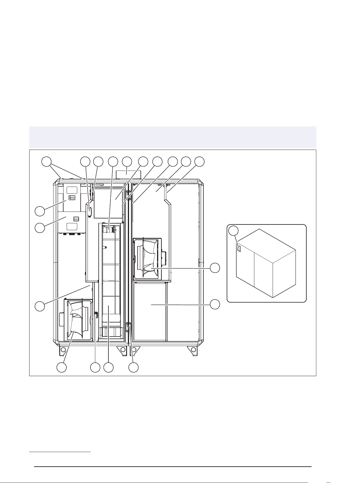
1.4 Product overview Topvex SR ......................... 1
1.5 Product overview Topvex TR.......................... 2
1.6 Overview of supplied parts............................. 3
1.7 Name plate ................................................3
1.7.1 Type designation ............................. 4
1.8 Product liability............................................ 5
2 Safety .................................................................5
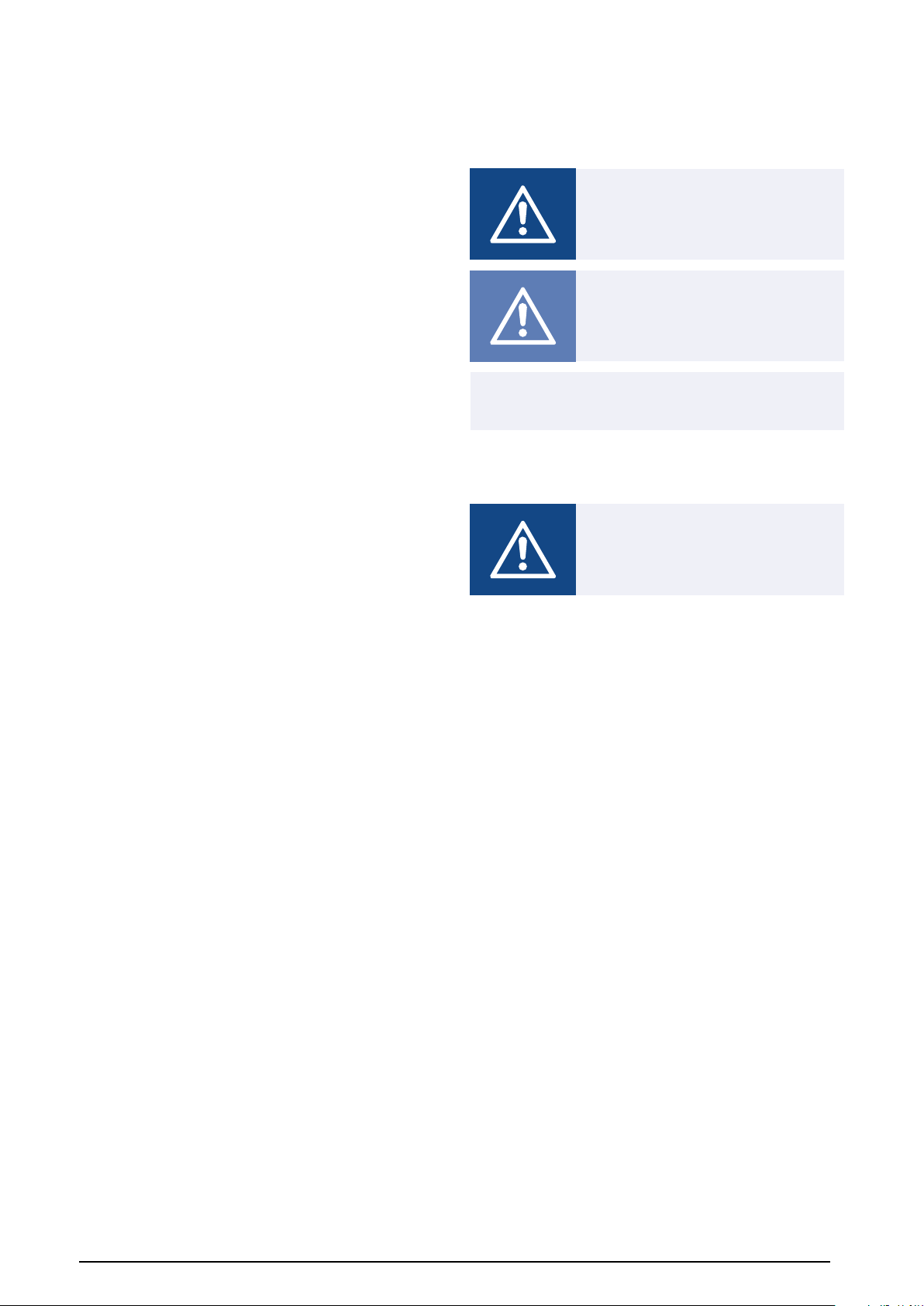
2.1 Safety definitions......................................... 5
2.2 Safety instructions ....................................... 5
2.3 Personal protective equipment ....................... 6
2.4 Safety labels on the product........................... 6
3 Transportation and storage ...................................... 7
3.1 To move the product with a forklift truck ............ 7
3.2 To move products with more than 1 section
from the pallet............................................. 7
3.3 To lift the product with a lifting frame ................ 8
3.4 Disassembly for transport through a
standard door opening.................................. 9
3.4.1 To disassemble the product ...............9
3.4.2 To divide the product into
sections....................................... 10
3.5 To assemble the product ............................. 11
3.6 To assemble the product sections ................. 12
4 Installation.......................................................... 14
4.1 To do before the installation of the
product.................................................... 14
4.2 To make the product level............................ 14
4.3 To adjust the heat exchangers
position ................................................... 15
4.4 To connect the ducts to the product ............... 16
4.4.1 Duct connection overview................ 16
4.5 To install the supply air sensor...................... 17
4.6 To put insulation on the ducts ....................... 17
4.7 To connect the water heating coil .................. 17
4.7.1 Technical data for water heating
coil ............................................. 18
4.8 Purge sector............................................. 19
4.8.1 Overview of the purge sector............ 19
4.8.2 To measure the air pressure
difference in the product.................. 19
4.8.3 Purge sector settings...................... 19
4.8.4 To adjust the purge sector ............... 20
4.9 NaviPad .................................................. 20
4.9.1 To install the NaviPad holder ............ 20
4.9.2 To connect the NaviPad .................. 20
4.10 To install the ODK roof ................................ 21
4.11 To install the Access control cabinet .............. 22
5 Electrical connection............................................. 23
5.1 To do before the electrical connection ............ 23
5.2 To connect the product to the power
supply..................................................... 24
5.3 To open the Access control cabinet ............... 24
5.4 To connect the supply air sensor ................... 25
5.5 To connect accessories............................... 25
6 Commissioning ................................................... 28
6.1 To do before the commissioning.................... 28
6.2 To do the commissioning ............................. 28
7 Operation........................................................... 28
7.1 To operate the NaviPad .............................. 28
7.1.1 NaviPad button ............................. 28
7.1.2 Overview of the NaviPad
dashboard ................................... 29
7.2 To do the start-up wizard in the
NaviPad .................................................. 29
7.3 Symbols in the control unit CU27–C
menu ...................................................... 29
7.4 To log on to the NaviPad with the applicable
user mode................................................ 30
7.4.1 User modes.................................. 30
7.5 Overview of the NavidPad software
menu ...................................................... 31
7.6 Overview of the NaviPad home page ............. 33
7.7 Data and settings ...................................... 34
7.8 Flow chart ................................................ 34
7.8.1 To use the flow chart ...................... 34
7.9 Language ................................................ 34
7.9.1 To change the language.................. 34
7.10 Time and date........................................... 35
7.10.1 To set the operation time ................. 35
7.11 Configuration............................................ 35
7.11.1 To do a configuration ...................... 35
7.12 System information .................................... 35
7.12.1 To add or adjust system
information................................... 35
7.13 Alarms .................................................... 35
7.13.1 To operate the alarms ..................... 35
7.14 To connect the NaviPad if the connection to
the product is lost ...................................... 36
7.15 To use a computer to show the user
interface .................................................. 36
7.16 To stop the product for maintenance .............. 36
8 Maintenance....................................................... 36
8.1 Maintenance schedule................................ 37
8.2 To clean the product................................... 38
8.3 To replace the filters ................................... 38
8.4 To replace the fan module ........................... 38
8.5 To replace the heat exchanger...................... 39
8.6 To replace the battery of the control unit
CU27-C................................................... 40
8.7 To reset tripped fuses ................................. 41

8.8 To reset the manual overheat protection for
electric heating coil .................................... 41
8.9 Spare parts .............................................. 41
9 Troubleshooting................................................... 42
10 Disposal........................................................... 43
10.1 To disassemble and discard the parts of the
product.................................................... 43
11 Warranty .......................................................... 43
12 Technical data ................................................... 44
12.1 Technical data overview .............................. 44
12.2 Weight data.............................................. 45
12.3 Product dimensions ................................... 46
12.3.1 Product dimensions for Topvex
SR20 and SR25 ............................ 47
12.3.2 Product dimensions Topvex SR 30,
35 .............................................. 48
12.3.3 Product dimensions Topvex SR60,
SR70, SR80 and SR100 ................. 49
12.3.4 Product dimensions Topvex TR20,
TR25, TR30 and TR35.................... 52
12.3.5 Product dimensions Topvex TR60,
TR70 and TR80 ............................ 54
12.3.6 Dimensions of the NaviPad and
NaviPad holder ............................. 55
12.3.7 Dimensions of the Access control
cabinet ....................................... 55
13 Accessory overview ............................................ 56
14 EU Declaration of conformity ................................ 57
15 UK Declaration of conformity ................................ 58


1 Introduction
1.1 Product description
The product is a compact air handling unit that is supplied
with rotating heat exchanger, electrical cabinet, control sys-
tem, CAV control, filters and EC motors as standard.
The product comes with 1 handle outside of the product cas-
ing. The other handles, NaviPad, NaviPad holder, supply air
sensor, external accessory power supply wiring kit and feet
to level the installation surface are supplied in a cardboard
box in the product.
Topvex SR is side connected and can be supplied with circu-
lar or rectangular duct connections. Topvex SR can be in-
stalled with a roof for outdoor installations (ODK).
Topvex TR is top connected and can be supplied with circular
or rectangular duct connections.
The VAV control, safety switch and other control equipment
are available as accessories.
An air handling unit with rectangular duct connections is not
supplied with duct joints. A duct connection kit is available as
accessory.
1.2 Intended use
The air handling unit is used for heat recovery ventilation,
connected to a circular or rectangular duct system. The
product is intended for installation in indoor environments
with ambient temperatures of between 0-50 °C. Applicable
installation locations are for example storage rooms, laundry
rooms or attics.
ODK models of the air handling unit can be installed in out-
door environments as the product is supplied with an outdoor
roof and the control unit installed in the casing.
Note:
Make sure that the ODK roof solution is applicable for the
weather conditions in your area.
The air handling unit is not applicable for transportation of air
that contains explosive, flammable or aggressive media.
The product solution is not applicable for locations where
there is a risk of explosion.
1.3 Document description
This document contains instructions for installation of the
product. The procedures must be done by approved person-
nel only.
Speak to Systemair for more information on how to install the
product in different installation locations.
1.4 Product overview Topvex SR
Note:
The illustration shows a left connected product.
19
3
2 1618 6 10
12
12
1317 497
5 15111 148
1

1. Supply air fan
2. Extract air fan
3. Filter for the supply air
4. Filter for the extract air
5. Heat exchanger
6. Rotor motor
7. Internal electrical cabinet
8. Heating coil (electrical or water)
9. Pressure transmitter (PDT1) for extract air filter and sup-
ply fan
10. Pressure transmitter (PDT2) for supply air filter and ex-
tract fan
11. Air flow sensor (AFS) only for units with electrical heat-
ing coil
12. Water battery connection
13. Extract air temperature sensor (ETS)
14. Efficiency temperature sensor (EFS)
15. Outdoor air temperature sensor (OS)
16. Exhaust air temperature sensor (EHS)
17. Access control cabinet1
18. Section assembly brackets
19. Name plate
1.5 Product overview Topvex TR
Note:
The illustration shows a left connected product.
19
6 18
7
13 9 14
8
4 16171011
15
2
3
5121
20
1. Supply air fan
2. Extract air fan
3. Filter for the supply air
4. Filter for the extract air
5. Heat exchanger
6. Rotor motor
7. Internal electrical cabinet
8. Heating coil (electrical or water)
9. Pressure transmitter (PDT1) for extract air filter and sup-
ply fan
10. Pressure transmitter (PDT2) for supply air filter and ex-
tract fan
11. Pressure transmitter for leakage protection
12. Air flow sensor (AFS) only for products with electrical
heating coil
13. Water battery connection
14. Extract air temperature sensor (ETS)
2
1. On ODK products the Access control unit is installed inside the product.

15. Efficiency temperature sensor (EFS)
16. Outdoor air temperature sensor (OS)
17. Exhaust air temperature sensor (EHS)
18. Access control cabinet
19. Section assembly brackets
20. Name plate
1.6 Overview of supplied parts
1
2
6
5
7
4
3
1. NaviPad holder
2. NaviPad
3. External accessory power supply wiring kit
4. Supply air sensor
5. Feet for product height adjustment
6. Handles
7. ODK roof kit (only supplied with ODK products)
1.7 Name plate
Fan
Filter
[P=1,2 kg/m3]
[kW]
[rpm]
[V]
[A]
[V]
[Motor kW] [Total kW]
[A]
[Hz] [IP] [kg]
16 17 1918 20 21
1 23
22
234567
8
9
10
11
12
13
14
15
3

1. Product name
2. Ampere, A
3. Total kW
4. Weight, kg
5. IP class, enclosure class
6. Voltage, V
7. Motor kW
8. Frequency, Hz
9. Certifications
10. Product key
11. Maximum fan speed, rpm
12. K-factor fan
13. Motor power, kW
14. Motor voltage, V
15. Motor current, A
16. Filter class
17. Part number/production number/production date
18. Supply air values
19. Supply filter class
20. Extract filter class
21. Manufacturer and country of production
22. Extract air values
23. Scannable code2
1.7.1 Type designation
Product name Topvex SR Topvex TR
Duct connection Side connected Top connected
Product size 20 20
25 25
30 30
35 35
60 60
70 70
80 80
100
Location of sup-
ply air connec-
tion and electric
supply
R (Right) R (Right)
L (Left) L (Left)
Heater types HWH (Water,
high power)
HWH (Water,
high power)
HWL (Water, low
power)
HWL (Water, low
power)
EL (Electric
heater)
EL (Electric
heater)
None None
Fan impeller Standard
(Composite)
Standard
(Composite)
M0 (Aluminium) M0 (Aluminium)
Weather pro-
tected outdoor
version
ODK N/A
Product
size
Electrical heater (kW)
20 5.2
25 5.2
30 3.5 7.1
35 3.5 7.1
60 3.5 7.1 10.4
70 3.5 10.4 14.2
80 5.2 12.3 19.4
100 7.1 15.7 24.6
4
2.
Use a mobile device to scan the scannable code and go to the Systemair documentation portal for more documentation and document
translations.

1.8 Product liability
Systemair is not liable for damages that the product causes
in these conditions:
• The product is incorrectly installed, operated or
maintained.
• The product is repaired with parts that are not original
spare parts from Systemair.
• The product is used together with accessories that are not
original accessories from Systemair.
2 Safety
2.1 Safety definitions
Warnings, cautions and notes are used to point out specially
important parts of the manual.
Warning
If you do not obey these instructions,
there is a risk of death or injury.
Caution
If you do not obey these instructions,
there is a risk of damage to the product,
other materials or the adjacent area.
Note:
Information that is necessary in a given situation.
2.2 Safety instructions
Warning
Read the warning instructions that follow
before you do work on the product.
5

• Read this manual and make sure that you understand the
instructions before you do work on the product.
• Obey local conditions and laws.
• The product must not be put into operation until the ma-
chine or ventilation system in which it is included in obeys
relevant directives.
• If an operation stop of the product for more than 48 hours
is planned, we recommend to not use cooling recovery.
This is to prevent microbial growth in the condensation
water in the supply air.
• The ventilation contractor and the operator are responsi-
ble for correct installation and intended use.
• Keep this manual at the location of the product.
• Do not install or operate the product if it is defective.
• Do not remove or disconnect safety devices.
• Make sure that you can read all warning signs and labels
on the product when it is installed. Replace labels that
have damage.
• Only permit approved personnel to work on the product
and to be in the adjacent area during all work on the
product.
• Make sure that you know how to stop the product quickly
in an emergency.
• Use applicable safety devices and personal protective
equipment during all work on the product.
• Before you do work on the product, disconnect the power
supply and wait until the product stops.
• If the maintenance is not correctly and regularly done,
there is risk of injury and damage to the product.
• Only do the maintenance as given in this manual. Speak
to Systemair technical support if other servicing is
necessary.
• Always use spare parts from Systemair.
• Sound levels exceeding 70 dB(A) may occur depending
on model and size. Visit www.systemair.com for more de-
tailed information about your product.
• The product is not to be used by persons, including chil-
dren, with reduced physical, sensory or mental capabil-
ities, or lack of experience and knowledge, unless they
have been given supervision or instruction.
• Do not allow children to play with the device.
2.3 Personal protective
equipment
Use personal protective equipment during all work on the
product.
• Approved eye protection
• Approved protective helmet
• Approved hearing protection
• Approved protective gloves
• Approved protective shoes
• Approved work clothing
2.4 Safety labels on the product
VARNING!
WARNUNG!
Innan anslutningar görs åtkomliga för beröring, måste alla
matningskretsar vara brutna.
Before obtaining access to terminals, all supply circuits must
be disconnected.
Avant d’accéder aux bornes, tous les circuits d’alimentation
doivent être déconnectés.
Vor dem Zugriff auf die Anschlussklemmen müssen alle
Versorgungsstromkreise unterbrochen werden.
AVERTISSEMENT!
WARNING!
STOP
4 min.
6

3 Transportation and
storage
Warning
Make sure that the product does not
become damaged or wet during
transportation. A damaged or wet
product can cause fire or electric shock.
Warning
Be careful during transportation of the
product. The product is heavy and there
is a risk of injury if it falls.
• Before the product is moved to the installation location,
examine the packaging for damages.
• Do not loosen packing belt or the transport screws until
the product is on location for installation.
• If lifting equipment is used, make sure that the lifting
equipment can hold the weight of the product. Refer to the
name plate for information. Do not lift the product by the
packaging.
Warning
Do not walk below a lifted product.
• Load and unload the product carefully.
• To move the product through an opening that is 900 mm
or smaller, refer to 3.4 Disassembly for transport through a
standard door opening.
• Keep the product in a dry and clean location with
protection from dust, rain, snow or direct sunlight during
storage. Make sure that the ambient temperature during
storage is between -10 and +30 °C. A stable ambient
temperature prevents damage from condensation.
• Make sure that the product has protection from
condensation during storage. The person who receives
the product must make sure that the protection from
condensation is sufficient.
• Keep the product in storage for maximum 1 year.
• Put covers on the duct connections during storage.
3.1 To move the product with a
forklift truck
Warning
Make sure that the forks of the forklift
truck or a pallet lift has sufficient length
and width.
Warning
The product is heavy, take the weight of
the product into consideration during
transport. Refer to 12.2 Weight data.
1Use a forklift truck to move the full product on the pallet.
Caution
If the product has more than 1 section,
do not move the sections 1 by 1 unless
the quick connection cables are discon-
nected. If a section is moved with the
quick connection cable connected, it can
cause damage to the product.
• Use long forks to move the pallet with a forklift truck
on the short side of the pallet.
• Use wide forks to move the pallet with a forklift truck
on the long side of the pallet.
3.2 To move products with more
than 1 section from the pallet
1Loosen the transport screws that attaches the product to
the pallet.
7

2Disconnect the quick connection cables in the top front
corner of the middle section.
3Remove the back panel:
a. Remove the screws with a screw driver and a drill
bit extension.
b. Remove the back panel.
4Use an Allen key to loosen the screw in the 2 section as-
sembly brackets on each side of the product.
5Move the product 1 section at a time from the pallet.
Warning
Be careful, the product can wobble if it is
moved too quickly.
3.3 To lift the product with a
lifting frame
Note:
Lifting equipment is not supplied by Systemair.
1Loosen the transport screws that attaches the product to
the pallet.
2Loosen the packing belt.
3If the product has more than 1 section, refer to 3.2 To
move products with more than 1 section from the pallet.
8

4Put pipes in the feet of the product. The hole diameter is
52 mm. Connect lifting straps from a lifting frame to the
pipes.
Warning
Make sure that the lifting straps are
safely attached to the pipes. There is a
risk of injury if the lifting straps come
loose.
Caution
The lifting frame must be larger than the
product. The lifting straps cannot touch
the product.
• On products with one section, put the pipes in the out-
er feet of the product.
• On products that can be divided into sections, put the
pipes in the feet of each section. Move 1 section at a
time.
5Lift the product.
3.4 Disassembly for transport
through a standard door
opening
Warning
2 persons are necessary to disassemble
the product safely. Stay on stable ground
during the work, and make sure that
there is sufficient space for the operation.
Note:
It is only necessary to disassemble the product for trans-
port through small openings of a minimum of 900 mm.
Note:
For weight of product sections, refer to 12.2 Weight data.
3.4.1 To disassemble the product
Note:
This instruction is applicable to Topvex SR20, SR25, SR30,
SR35, TR20, TR25, TR30 and TR35 for transport through
a standard door.
9

1Remove the doors, do these steps:
a. Remove the hinge covers with a screwdriver.
A
b. Remove the hinge pins (A).
c. Remove the doors.
2Remove the back panel, do these steps:
a. Remove the screws with a screw driver and a drill
bit extension.
b. Remove the back panel:
3.4.2 To divide the product into
sections
Note:
This instruction is applicable to Topvex SR60, SR70, SR80,
TR60, TR70 and TR80 for transport through a standard
door.
1Open the doors of the product.
10

2If it is necessary to get access to the quick connection
cables and the section assembly brackets, remove the
filters.
a. On Topvex SR:
b. On Topvex TR:
3Disconnect the quick connection cables.
4Use an Allen key to loosen the screw in the 2 section as-
sembly brackets on each side of the product.
3.5 To assemble the product
Note:
This instruction is applicable to Topvex SR20, SR25, SR30,
SR35, TR20, TR25, TR30 and TR35 for transport through
a standard door.
11

1Install the back panel, do these steps:
a. Attach the back panel.
b. Tighten the screws with a screwdriver and a drill bit
extension.
2Install the doors, do these steps for each door:
a. Put the door in the correct position and connect the
hinge parts.
b. Install the hinge pins.
c. Attach the hinge cover.
3.6 To assemble the product
sections
Note:
This instruction is applicable to Topvex SR60, SR70, SR80,
TR60, TR70 and TR80 for transport through a standard
door.
1Use a pallet lift to put the sections of the product in
position.
2Open all doors.
3Lock the sections with a washer and a screw on each
side of the 8 section assembly brackets. Use an Allen
key to tighten the screws.
12

4Connect the quick connection cable between the side
section and middle section on each side. Refer to the
marks on the cable for correct connection.
5Install the filters.
a. On Topvex SR:
b. On Topvex TR:
13

4 Installation
4.1 To do before the installation
of the product
• Make sure that you have the necessary installation
accessories:
– Refer to chapter 13 Accessory overview for an over-
view of the accessories.
– If you install the product with free suction or free dis-
charge, it is necessary to install a protection grille.
Make sure that the safety distance agrees with the
standard DIN EN ISO 13857 and the standard DIN
24167–1.
• Examine the packaging for transportation damage and re-
move the packaging from the product carefully.
• Examine the product and all components for damage.
• Make sure that the information on the name plate agrees
with the order confirmation.
• Install the product in a location where there is space for
commissioning, troubleshooting and maintenance.
• Make sure that the installation location is clean and dry,
for full safety during electrical work.
• Make sure that the installation surface has sufficient ca-
pacity to hold the weight of the product.
• Make sure that the duct connection agrees with the air
flow direction of the ventilation system. Refer to the air
flow direction arrows in 4.4.1 Duct connection overview.
• Make sure that all cable glands are tight against the ca-
bles to prevent leaks.
• If possible, do not put the product directly against the wall.
If the product is to be installed directly against the wall, put
insulation on the wall to decrease vibrations and unwanted
noise.
• If the product is installed in an outdoor environment, do
not let the product be out of power.
• Obey local laws and conditions for installation.
• Make sure that all equipment is supplied with product.
• Put the outdoor air intake on the northern east side of the
building, away from other exhaust outlets.
• Install the loose parts from the cardboard box in the
product.
• If the product is set to OFF for a long time after the product
is installed, operate the product for 15 minutes or more
each day. If the product is not operated each day, it can
cause damage to the motor bearings.
Caution
If the product is not operated each day, it
can cause damage to the fan motor
bearings.
• If the product is installed outside and is not in operation,
put protection from condensation on the product.
4.2 To make the product level
1If the floor is not level, install the supplied feet on the
product. Adjust the feet until the product is level.
14

2Adjust the doors of the product.
a. Remove the hinge cover.
b. Loosen the top and bottom screws on the outer side
of the hinge to adjust the door vertically.
c. Loosen the middle screws on the inner side of the
hinge to adjust the door horizontally.
d. Tighten the screws.
e. Attach the hinge cover.
4.3 To adjust the heat exchangers
position
Note:
Make sure that the product is level.
1Select which side of the heat exchanger that needs the
adjustment.
2On Topvex SR20, SR25, SR30, SR35, TR20, TR25,
TR30 and TR35, remove the door beam to get access to
the heat exchanger.
a. Remove the 4 screws (A) for the door beam.
b. Remove the door beam.
A
3Loosen the bolt (A) and adjust the position of the heat
exchanger with bolt (B). Tighten the bolts when you have
the correct position of the heat exchanger.
A
B
15

4.4 To connect the ducts to the
product
Warning
Rotating fan impeller. Make sure that the
product is not energized until all the ducts
are connected or protected with a grille.
1For products with circular duct connections, do these
steps:
a. Put the duct on the duct joint of the product. Pull the
duct over the rubber rings on the duct joint.
b. Use self drilling screws to attach the duct to the duct
joints.
2For products with rectangular duct connections, do these
steps:
a. Install a duct connection kit. The duct connection kit
is available as an accessory. Refer to 13 Accessory
overview. Use sealing tape and M8 screws to install
the duct connection kit on the duct opening.
Note:
Sealing tape and M8 screws are not supplied by Systemair.
b. Systemair recommends to install the ducts together
with flexible connection DS. Use guide rails to install
the flexible connection on the duct joints. Guide rails
are not supplied by Systemair.
3If you install the product near a duct bend, do these
steps to prevent vibrations, unwanted noise and de-
creased air pressure:
a. Measure the distance (A) between the product and
the duct bend.
b. Make sure that the distance (A) is a minimum of 2.5
x the diameter (B) of the duct system. For circular
ducts, (B) is the nominal diameter. For rectangular
ducts, (B) is the hydraulic diameter.
AA
B
4.4.1 Duct connection overview
L
L
R
R
16
Other manuals for Topvex SR
3
This manual suits for next models
1
Table of contents
Other System air Air Cleaner manuals