manuals.online logo
Brands
  1. Home
  2. •
  3. Brands
  4. •
  5. System Sensor
  6. •
  7. Smoke Alarm
  8. •
  9. System Sensor 2151A User manual

System Sensor 2151A User manual

D100-04-00 1 I56-1015-000
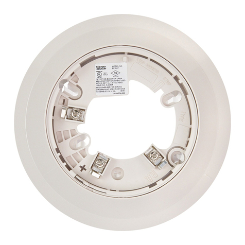
2151A Low Profile
Photoelectronic Plug-in
Smoke Detector
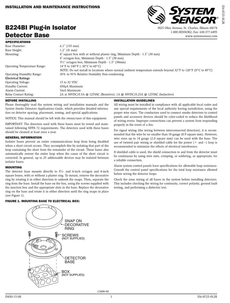
INSTALLATION AND MAINTENANCE INSTRUCTIONS
6581 Kitimat Rd., Unit #6, Mississauga, Ontario, L5N 3T5
1-800-SENSOR2, FAX: 905-812-0771
www.systemsensor.ca
Before Installing
Please thoroughly read the System Sensor manual I56-
407, Guide for Proper Use of System Smoke Detectors,
which provides detailed information on detector spacing,
placement, zoning, wiring, and special applications. Cop-
ies of this manual are available at no charge from System
Sensor. Please also refer to CAN/ULC-S524-M91, Stan-
dard for the Installation of Fire Alarm Systems, and CEC
Part 1, Sec. 32.
NOTICE: This manual should be left with the owner/user
of this equipment.
IMPORTANT: The detector used with this base must be
tested and maintained regularly following CAN/ULC-S536
requirements. The detector used with this base should be
cleaned at least once a year.
General Description
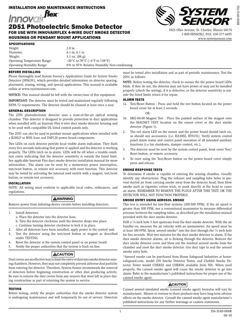
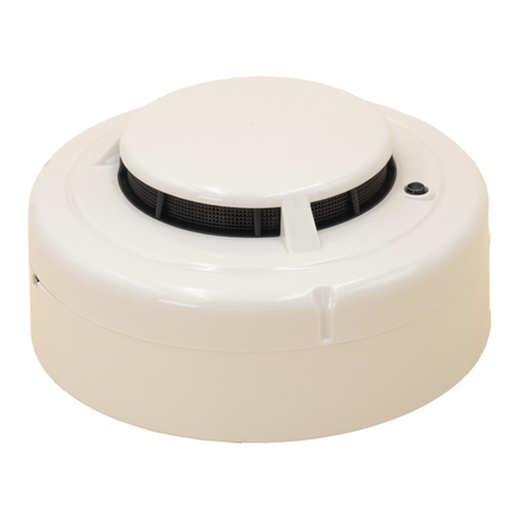
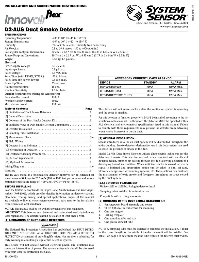
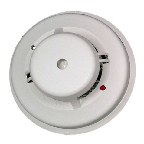
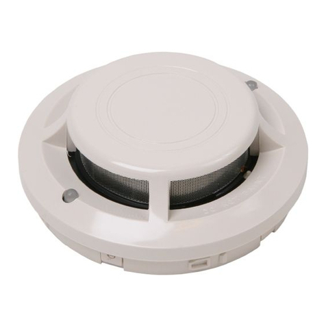
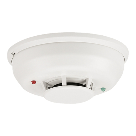
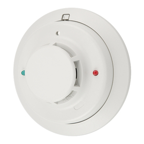
The 2151A low-prole photoelectronic detector uses a
state-of-the-art optical sensing chamber. This detector
is designed to provide open area protection and to be
used with compatible ULC-listed control panels only. The
capability of plugging the detector into a variety of special
bases makes it more versatile than equivalent direct-wired
models.
Specifications
Size
Height: 1.7 inches (43 mm)
Diameter: 4.0 inches (101 mm)
Weight: 3.6 oz. (102 g)
Operating Voltage: 10 to 32 VDC
Max. Avg. Standby Current: 120uA
Operating Temperature Range: 0° to 49°C (32° to 120°F)
Operating Humidity Range: 10% to 93% Relative Humidity noncondensing
Latching Alarm: Reset by momentary power interruption.
Two LEDs on each detector provide local 360° visible
alarm indication. They ash every ten seconds indicating
that power is applied and the detector is working properly.
The LEDs latch on in alarm. Remote LED annunciator
capability is standard and may be implemented through
an optional accessory RA400ZA. The alarm can be reset
only by a momentary power interruption. These detectors
may be tested by activating the internal reed switch with a
magnet.
Base Selection And Wiring Guide
Refer to the installation instructions for the Plug-in De-
tector Bases for base selection and wiring instructions.
System Sensor has a variety of detector bases available
for this smoke detector, including 2-wire applications with
and without relays and/or current limiting resistors, 4-wire
and 120VAC applications ( see list below ).
All bases are provided with screw terminals for power,
ground, remote annunciator connections and relay con-
tact connections, if applicable. The electrical ratings for
each detector-base combination are also included in the
base installation instructions.
Adapter Base Selection Guide
Base Model Loop Current Alarm Nominal Current Draw
Number Type Limit Resistor Contact Type Voltage on Alarm (mA)
B110LP 2-wire* No — 12/24VDC 10–100**
B112LPA 4-wire Yes Form A&C 24VDC 14–39
B114LPA 4-wire Yes Form A&C + A Supy. 120VAC 75 mAAC Max
B116LPA 2-wire* No Form C 24VDC 12–100**
B401 2-wire* No — 12/24VDC 10–100**
*Functionality contingent on panel compatibility **Must be limited by control panel †Flangeless base
Relay Contact Ratings: Resistive or Inductive (60% power factor) load.
Form A: 2.0A at 30 VAC/DC
Form C: 0.6A at 110VDC, 2.0A at 30VDC - 1.0A at 125VAC, 2.0Aat 30VAC

D100-04-00 2 I56-1015-000
Installation
NOTE: All wiring must conform to applicable local codes,
ordinances, and regulations.
NOTE: Verify that all detector bases are installed, that the
initiating-device circuits have been tested, and
that the wiring is correct. (Refer to detector base
manual for testing procedure.)
WARNING
Remove power from initiating-device circuits before in-
stalling detectors.
1. Install detectors:
a. Place the detector into the detector base.
b. Turn the detector clockwise until the detector drops
into place.
c. Continue turning detector clockwise to lock it in
place.
2. Tamper Resistance: The detector bases can be made
tamper resistant. When capability is enabled, detectors
cannot be removed from the base without the use of a
tool. See the detector base installation manual of the
detector base for details in using this capability.
3. After all detectors have been installed, apply power to
the control unit.
4. Test the detector using the magnet as described under
TESTING.
5. Reset the detector at the system control panel.
6. Notify the proper authorities that the system is back on
line.
LED
LED
TEST MODULE
SOCKET
TEST
MAGNET
PAINTED
SURFACE
Figure 1. Bottom and side views showing position of test magnet:
CAUTION
Dust covers are an effective way to limit the entry of dust
into smoke detector sensing chambers. However, they
may not completely prevent airborne dust particles from
entering the detector. Therefore, System Sensor recom-
mends the removal of detectors before beginning con-
struction or other dust producing activity.
Be sure to remove the dust covers from any sensors that
were left in place during construction as part of returning
the system to service.
Testing
Before testing, notify the proper authorities that the
smoke detector system is undergoing maintenance and
will temporarily be out of service. Disable the zone or
system undergoing maintenance to prevent unwanted
alarms. Detectors must be tested after installation and as
part of periodic maintenance. Test the 2151Aas follows:
NOTE: Before testing the detector, check to ensure the
the LEDs blink. If they do not, the detector has
lost power (check the wiring) or it is defective
(return it for repair).
A. Test Magnet (System Sensor model no. M02-04-01)
1. Place the magnet against the cover in the location
designated by the raised mark to activate the test
feature (see Figure 1).
2. The LEDs should latch ON within 5 seconds indi-
cating alarm and annunciating the panel.
A78-2424-00
D100-04-00 3 I56-1015-000
Figure 2:
A78-2456-00
B. Test Module ( MOD400R)
Use the MOD400R with a DMM or voltmeter to check
the detector sensitivity as described in the MOD400R
manual.
C.Aerosol Generator (Gemini 501)
Set the generator to represent 4% to 5%/ft. obscura-
tion as described in the Gemini 501 Manual. Using the
bowl- shaped applicator, apply aerosol until unit alarms.
Notify the proper authorities that the system is back on
line.
Detectors that fail these tests should be cleaned as
described under MAINTENANCE and retested. If the
detectors still fail these tests, they should be returned for
repair.
Maintenance
It is recommended that the detector be removed from
its mounting base to facilitate cleaning. The detector is
cleaned as follows:
NOTE: Before removing the detector, notify the proper
authorities that the smoke detector system is
undergoing maintenance and will be temporarily
out of service. Disable the zone or system under-
going maintenance to prevent unwanted alarms.
1. Remove the detector cover by prying away the four
side tabs with a small-bladed screwdriver, and then
pulling the cover from the base.
2. Vacuum the screen carefully without removing it. If
further cleaning is required continue with Step 3, oth-
erwise skip to Step 6.
3. Remove the screen assembly by pulling it straight out
(see Figure 2). Vacuum the inside.
4. Clean the vaned chamber piece by vacuuming or blow-
ing out dust and particles.
5. To replace the screen, orient it so that the arrow on top
aligns with the arrow on the printed circuit board. Care-
fully push the screen assembly onto the vaned cham-
ber making sure it ts tightly.
6. Replace the cover by gently pushing it until it locks in
place.
7. Reinstall the detector.
8. Notify the proper authorities that the system is back on
line.
REMOVABLE
COVER
VANED
CHAMBER
REMOVABLE
SCREEN
D100-04-00 4 I56-1015-000
© System Sensor 2004
Three-Year Limited Warranty
System Sensor warrants its enclosed smoke detector to be free from
defects in materials and workmanship under normal use and service for a
period of three years from date of manufacture. System Sensor makes no
other express warranty for this smoke detector. No agent, representative,
dealer, or employee of the Company has the authority to increase or alter
the obligations or limitations of this Warranty. The Company’s obligation
of this Warranty shall be limited to the repair or replacement of any part
of the smoke detector which is found to be defective in materials or work-
manship under normal use and service during the three year period com-
mencing with the date of manufacture. After phoning System Sensor’s
toll free number 800-SENSOR2 (736-7672) for a Return Authorization
number, send defective units postage prepaid to: System Sensor, Repair
Department, RA #__________, 6581 Kitimat Rd., Unit #6, Mississauga,
Ontario, L5N 3T5. Please include a note describing the malfunction and
suspected cause of failure. The Company shall not be obligated to repair
or replace units which are found to be defective because of damage,
unreasonable use, modications, or alterations occurring after the date
of manufacture. In no case shall the Company be liable for any conse-
quential or incidental damages for breach of this or any other Warranty,
expressed or implied whatsoever, even if the loss or damage is caused by
the Company’s negligence or fault. Some legislations do not allow the ex-
clusion or limitation of incidental or consequential damages, so the above
limitation or exclusion may not apply to you. This Warranty gives you spe-
cic legal rights, and you may also have other rights under common law.
Please refer to insert for the Limitations of Fire Alarm Systems

Other System Sensor Smoke Alarm manuals

System Sensor B210LP User manual

System Sensor

System Sensor B210LP User manual

System Sensor BEAM1224SA User manual

System Sensor

System Sensor BEAM1224SA User manual

System Sensor 2100 User manual

System Sensor

System Sensor 2100 User manual

System Sensor Inovair Flex D4240 User manual

System Sensor

System Sensor Inovair Flex D4240 User manual

System Sensor Innovair DH100ACDCLWP User manual

System Sensor

System Sensor Innovair DH100ACDCLWP User manual

System Sensor 2151TA User manual

System Sensor

System Sensor 2151TA User manual

System Sensor 2100ARFT User manual

System Sensor

System Sensor 2100ARFT User manual

System Sensor B501BH User manual

System Sensor

System Sensor B501BH User manual

System Sensor BEAM200 User manual

System Sensor

System Sensor BEAM200 User manual

System Sensor B224RB User manual

System Sensor

System Sensor B224RB User manual

System Sensor innovair flex D4120W User manual

System Sensor

System Sensor innovair flex D4120W User manual

System Sensor 2351E User manual

System Sensor

System Sensor 2351E User manual

System Sensor 1400 User manual

System Sensor

System Sensor 1400 User manual

System Sensor 7251 User manual

System Sensor

System Sensor 7251 User manual

System Sensor B402B User manual

System Sensor

System Sensor B402B User manual

System Sensor DNRHS User manual

System Sensor

System Sensor DNRHS User manual

System Sensor INNOVAIR DH100ACDCP User manual

System Sensor

System Sensor INNOVAIR DH100ACDCP User manual

System Sensor 2112/24R User manual

System Sensor

System Sensor 2112/24R User manual

System Sensor 2112 User manual

System Sensor

System Sensor 2112 User manual

System Sensor TEMPORAL TONE SOUNDER BASE B501BHT User manual

System Sensor

System Sensor TEMPORAL TONE SOUNDER BASE B501BHT User manual

System Sensor B112LPA User manual

System Sensor

System Sensor B112LPA User manual

System Sensor PERTRONIC DNRW User manual

System Sensor

System Sensor PERTRONIC DNRW User manual

System Sensor 2251EIS User manual

System Sensor

System Sensor 2251EIS User manual

System Sensor ECO1003ABLINK User manual

System Sensor

System Sensor ECO1003ABLINK User manual

Popular Smoke Alarm manuals by other brands

LST HT-11003 Specification sheet

LST

LST HT-11003 Specification sheet

Firex G-6GC manual 

Firex

Firex G-6GC manual 

Smartwares FSM-114 user manual

Smartwares

Smartwares FSM-114 user manual

FireAngel ST-630-INT manual

FireAngel

FireAngel ST-630-INT manual

Aico Ei100R manual

Aico

Aico Ei100R manual

Kidde 0976CA user manual

Kidde

Kidde 0976CA user manual

Aztech Kyla Smart Smoke Sensor user guide

Aztech

Aztech Kyla Smart Smoke Sensor user guide

Fire-Lite Alarms 6424 quick start guide

Fire-Lite Alarms

Fire-Lite Alarms 6424 quick start guide

Siterwell GS558A user manual

Siterwell

Siterwell GS558A user manual

Airam ALE! operating instructions

Airam

Airam ALE! operating instructions

Edwards Signaling SuperDuct TSD-SJ Installation sheet

Edwards Signaling

Edwards Signaling SuperDuct TSD-SJ Installation sheet

ADEMCO 5808 installation instructions

ADEMCO

ADEMCO 5808 installation instructions

clare ClareOne CLR-C1-SMK Installation sheet

clare

clare ClareOne CLR-C1-SMK Installation sheet

Ei Electronics Ei405TY RF Optical Technical specifications

Ei Electronics

Ei Electronics Ei405TY RF Optical Technical specifications

GST I-9102 installation instructions

GST

GST I-9102 installation instructions

Kidde P3010CU user manual

Kidde

Kidde P3010CU user manual

ELRO CBFS58R instruction manual

ELRO

ELRO CBFS58R instruction manual

Ningbo Siterwell Electronics GS536 user manual

Ningbo Siterwell Electronics

Ningbo Siterwell Electronics GS536 user manual

manuals.online logo
manuals.online logoBrands
  • About & Mission
  • Contact us
  • Privacy Policy
  • Terms and Conditions

Copyright 2025 Manuals.Online. All Rights Reserved.