.
SV~TADN
~DONNER
FEATURES
e THREE OUTPUTS -
IND
E
PENDENTLY
ADJUSTABLE
e AUTOMAT
IC
EL
ECTRON
IC
CURREN
T
LI
M
IT
ING
e NO TURN
ON
/TURN OFF TRAN
SI
ENTS
e THREE INDEPENDENT DUAL RANGE M
ET
ERS
e OVE
RVOLTAGE
PROTECTION OPTION
ELECTRICAL SPECIFICATIONS
Input: 220
VAC
± 10%; 47-65Hz
Output
:<1>
Triple Floating; isolated from ground, 300
VDC
max.
A)
0 to + 8 VDC, 3 ampere; rating reduces to 2 ampere at 0
VDC
.
B)
0 to + 32 VDC, 1ampere; rating reduces to 0.5 ampere at
OVDC.
C)
0 to -32VDC at 1ampere; rating reduces to 0.5 ampere at
OVDC.
All outputs are referenced to a common return electrica
ll
y
isolated from chassis ground.
Regulation,Line: 0.02% or 2 mV*, for 200-240VAC line change,
at any output within specifications.
Regul
at
ion, Load: 0.02%
or
5 mV*, no load to full load, at any
output within specifications.
Ripple: 500
pV
RMS
; 3
mV
p-p.
(10
MHz)
Stab
ili
ty: 0.05% or
10
mV*, for 8 hours after warm-up.
Measured at constant line voltage, load and ambient
temperature.
Tem
perature
Co
effi
ci
ent: (0.02% + 400 ,uVWC
Temperature Range: 0
oc
to + 40 °C. ·
Recove
ry
Time: 50 microseconds to within 0.05%
or
15
mV
* of
output voltage, for 80% step change
in
rated load (.21oad to
full load)
Short Circuit Protection: Automatic Electronic Current
Li
miting.
AC Power Input Protection: Fuse.
Voltage Adjustment Range: Continously adjustable vernier
controls.
*Whichever is greater.
(1)
At maximum line voltage condition, the total output current should not exceed
80%
of
total allowable current.
SVSTRCN
rlf£?.:)
CONNER
G M B H
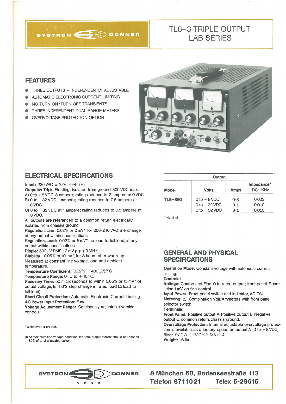
TL8-3
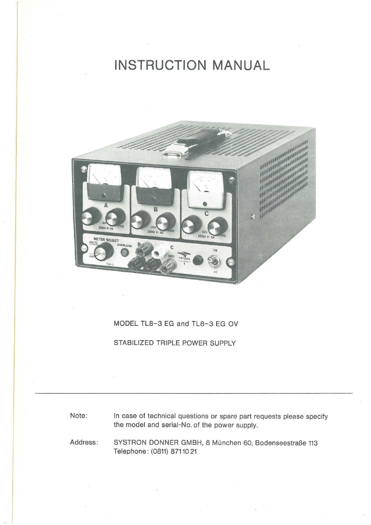
TRIPLE OUTPUT
LAB
SERIES
Output
Impedance*
Model Volts Amps
TL8-3EG
0 to
+8VDC
0-3
0 to
+32
V
DC
0-
1
Oto
-32VDC
0-
1
• N
omi
nal
GENERAL AND PHYSICAL
SPECIRCATIONS
DC-1
KHz
0.003
0.010
0.010
Operation Mode: Constant voltage with automatic current
limiting.
Controls:
Voltage: Coarse and Fine;0 to rated output; front panel. Reso-
lution 1
mV
on fine contr
ol.
Input Power: Front panel switch and indicator,
AC
ON.
Metering:
(3)
Combination Volt/Ammeters with front panel
selector switch.
Terminals:
Front Panel: Positive output
A,
Positive output
B,
Negative
output
C,
common return, chassis ground.
Overvoltage Protection: Inte
rn
al
adjustable overvoltage protec-
tion is available, as a factory option on output A (0 to + 8
VDC)
Size: 77/a" W x 47/a" H x
12e/1e"
D
Weight: 16 lbs.
8 Mi.inchen
60,
BodenseestraBe 113
Telefon
87110
21
Telex
5-29615