T-MAG AMX Series Instruction Manual

Enhance your process
Engineering
Operation &
Maintenance
Mag
Drive
1/2HP
through
5HP
TM4, TM6 & TM10
AMX SERIES

SECTION 1 CAUTIONS—READ FIRST!
.............................................
1
SECTION 2 PUMP DESIGNATION SYSTEM
.........................................
3
SECTION 3 HOW IT WORKS
.......................................................
4
SECTION 4 DIMENSIONAL DRAWINGS
............................................
5
SECTION 5 PERFORMANCE
A. 1/2 HP (0.4 kW) Performance Curves
50 Hz
..............................................................
6
60 Hz
..............................................................
7
B. 1 HP (0.75 kW) Performance Curves
50 Hz
..............................................................
8
60 Hz
..............................................................
9
C. 2 HP (1.5 kW) Performance Curves
50 Hz
.............................................................
10
60 Hz
.............................................................
11
D. 3 HP (2.2 kW) Performance Curves
50 Hz
.............................................................
12
60 Hz
.............................................................
13
E. 5 HP (3.7 kW) Performance Curves
50 Hz
.............................................................
14
60 Hz
.............................................................
15
F. 5 HP (3.7 kW) Oversize Inlet Performance Curves
50 Hz
.............................................................
16
60 Hz
.............................................................
17
SECTION 6 SUGGESTED INSTALLATION, OPERATION & TROUBLESHOOTING
....
18
SECTION 7 ASSEMBLY / DISASSEMBLY
..........................................
21
SECTION 8 EXPLODED VIEW & PARTS LISTING
Glass-Filled Polypropylene Models 28
Carbon-Fiber Reinforced ETFE Models
......................................
30
TABLE OF CONTENTS
......................................
1
TEMPERATURE LIMITS
Glass-Filled Polypropylene
32°F (0° C) to 175°F (79°C)
Carbon-Fiber Reinforced ETFE
Viton -40°F (-40°C) to 350°F (177°C)
EPDM -60°F (-51°C) to 280°F (138°C)
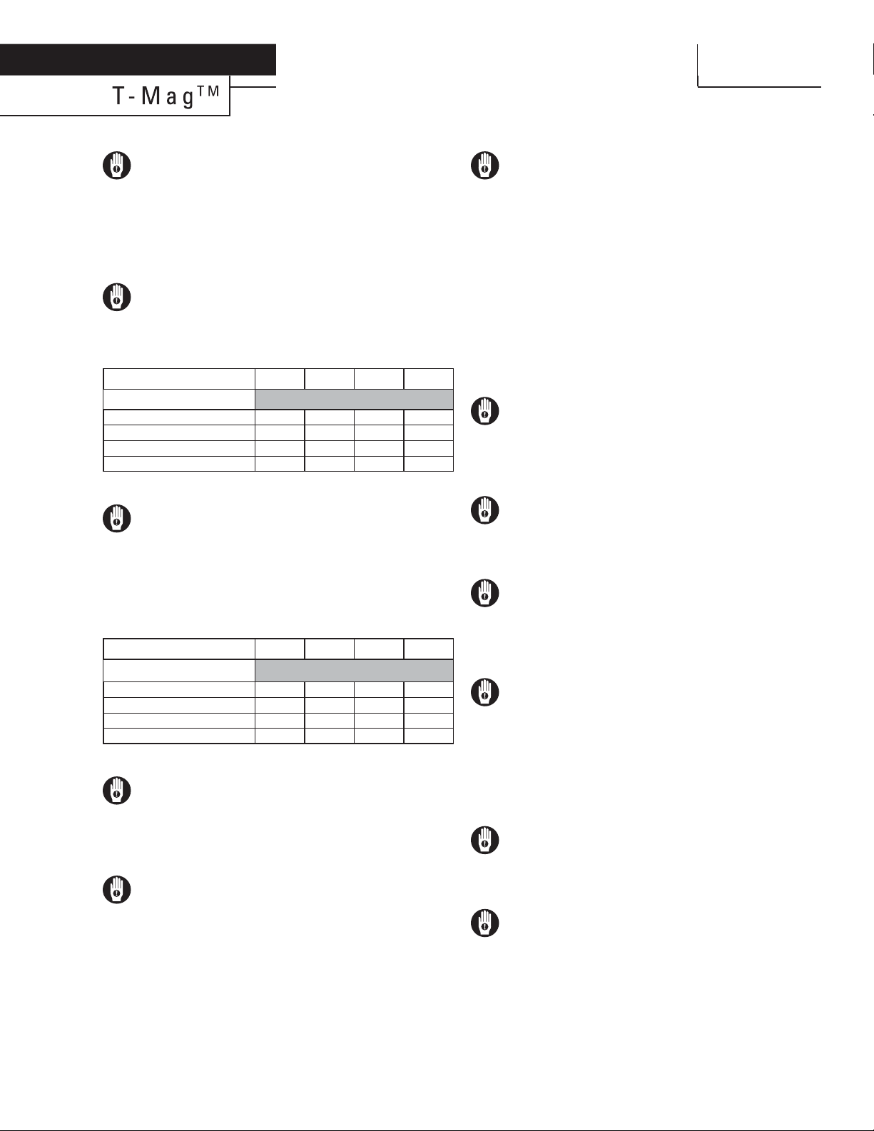
CAUTION:
Operating Temperature: °F (°C) 68 (20) 104 (40) 140 (60) 176 (80)
Maximum Pressure: psig (bar)
1/2 HP (0.40 kW) 50 (3.4) 47 (3.2) 43 (2.9) 36 (2.5)
1 HP (0.75 kW) 71 (4.9) 64 (4.4) 54 (3.7) 43 (2.9)
2 HP (1.5 kW) & 3 HP (2.2 kW) 85 (5.9) 78 (5.4) 64 (4.4) 50 (3.4)
5 HP (3.7 kW) 85 (5.9) 78 (5.4) 64 (4.4) 50 (3.4)
(Above data based on water)
CAUTION:
Operating Temperature °F (°C) 68 (20) 104 (40) 140 (60) 176 (80)
1/2 HP (0.40 kW) 15 (4.0) 20 (5.3) 25 (6.6) 30 (7.9)
1 HP (0.75 kW) 15 (4.0) 15 (4.0) 20 (5.3) 20 (5.3)
2 HP (1.5 kW) & 3 HP (2.2 kW) 20 (5.3) 20 (5.3) 30 (7.9) 40 (10.6)
5 HP (3.7 kW) 30 (7.9) 30 (7.9) 50 (13.2) 75 (19.8)
(
Above data based on water)
CAUTION:
CAUTION:
CAUTION:
WARNING:
WARNING:
WARNING:
CAUTION:
WARNING:
WARNING:
Section 1
CAUTIONS—READ FIRST!
Minimum Flow: GPM (LPM)
The pump’s maximum operating
pressure will change with variations in operating
temperature and size of the pump. Please refer
to table below for the recommended maximum
operating pressures for T-MAG™ pumps.
0°F (-17°C) to 212°F (100°C)
Operating a T-MAG™ pump below the
minimum ow rates shown below may result in a
signicant rise in temperature within the interior
of the pump. Operation of the pump below these
minimum levels may also result in increased radial
and axial forces on the shaft, bushing and impeller
assembly. These resulting conditions may aect the
pump’s performance and service life.
Do not run the pump without uid
for extended periods of time. Depending upon
application conditions, dry-running the pump may
cause the temperature of the internal components to
rise, resulting in damage to the pump internals.
When selecting a pump for a specic
application be sure to consider the concentration
of the uid being pumped. Changes in uid
concentration may aect viscosity and specic
gravity. Other physical properties, such as
corrosiveness, may also change with variations in
uid concentration.
Mag-drive pumps are generally intended
for use with uids with little or no particulate in the
process. Excessive or large particulates in the process
media will adversely aect pump performance and
service life. For process media with more than 5%
by volume particulates or with solids larger than
50µ (microns), it is recommended that you use
another pump technology. For process media with
5% or less by volume particulates and with solids
smaller than 50µ, it is recommended that you use the
Sintered SiC bearing option in the T-MAG™ pump.
However, please note that a reduced service life may
still be experienced versus a uid process with no
particulate.
Always perform an exterior inspection of
the pump prior to installation. Look for damage that
may have been inicted during shipment. Also, check
the free rotation of the pump by using a small at
head screwdriver to turn the fan motor.
Inspect the pump nameplate prior
to installation to insure the proper materials of
construction, motor power rating, impeller dimesion
and uid connection sizes.
Always prime pump before start-up. Lack
of uid at start-up may cause excessive heat buildup
within the pump which may cause a reduction in
service life of the components. Also, insure that all
inlet process valves are open at start-up.
At initial start-up of the pump, after
complete and proper wiring of the unit, check the
pump rotation by quickly turning on and then o the
pump power. After shut down, inspect the fan rotation
through the back fan guard. While looking through
the rear motor fan guard, the fan should be rotating
clockwise. Once proper rotation has been established,
follow all start-up procedures for the system.
During a systems or plant wide power
failure, always turn o all rotating equipment to
prevent sudden increases in system pressures once
power is restored.
Before normal shut down of the pump for
service or at the completion of a process run, always
slowly close the discharge valve of the pump to
prevent reverse ow from the discharge lines. Once the
discharge valve is closed, immediately shut down
the pump.
2
CAUTION:
CAUTION:
CAUTION:
WARNING:
CAUTION:
CAUTION:
CAUTION:
CAUTION:
CAUTION:
Section 1
CAUTIONS - READ FIRST! CONT.
Periodically inspect the interior of the
pump for damage or wear, especially when the
pump is being used with a uid near its freezing
point. In some cases the uid may crystallize even
when the pump is only shut down for a short
period. Use of an automatic drain system or heat
tracing may be used to counter this process.
When choosing pump materials, be
sure to check the temperature limits for all wetted
components. Example: Viton® has a limit of 350°F
(177°C), but Glass-Filled Polypropylene has a maximum
limit of only 175°F (79°C).
Maximum temperature limits are based
upon mechanical stress only. Certain chemicals
will signicantly reduce maximum safe operating
temperatures. Consult Chemical Resistance Guide for
chemical compatibility and temperature limits.
Prevention of static sparking - If static
sparking occurs, re or explosion could result.
Pump, valves, and containers must be grounded to
a proper grounding point when handling ammable
uids or whenever discharge of static electricity is
a hazard. For T-MAG™ pumps, only ETFE models oer
statically dissipative materials. Check with your local,
state or government agencies for grounding requirements
for your area.
The process uid and cleaning uids
must be chemically compatible with all wetted components
See a chemical compatibility guide for details.
Never disconnect any uid process lines
that may contain pressurized uid. Be sure to close
any isolation valves and safely drain any line presssure
before servicing pump. Failure to do so may result in
process uid being sprayed from a loosened connection.
Never attempt to reuse damaged pump
components. If the impeller, casing, bushing or any
other internal parts show signs of wear, replace
them immediately with factory approved spare parts.
Using damaged parts may result in process uid leaks
or bodily injury.
With an increase in specic gravity the
required torque to turn the impeller increases as
well. The increase in torque needed can exceed the
magnet’s ability rotate the impeller of pump resulting
in little or no ow.
When installing a Mag-Drive pump into
an application requiring an ATEX pump, an ATEX
certied motor must be used.

MAG-DRIVE
SPECIALTY CODES
Section 2
DESIGNATION SYSTEM
LEGEND
TMXXX /XX /XX /XXX /XX / XXX
MOTOR
VOLTAGE
MAG-DRIVE
PUMP IMPELLER DIAMETER
O-RINGS / GASKETS
BEARING
PUMP
SIZE
CASING MATERIAL
SPECIALTY
CODE
(if applicable)
BEARING/BUSHING DETAIL*
Bearing Shaft Wear Ring Front Thrust Ring Rear Thrust Ring
CCarbon 995 Al Ceramic Carbon 995 Al Ceramic 995 Al Ceramic
RRulon 995 Al Ceramic Rulon 995 Al Ceramic 995 Al Ceramic
A995 Al Ceramic 995 Al Ceramic Rulon 995 Al Ceramic 995 Al Ceramic
SSintered Sic Sintered Sic Sintered Sic Sintered Sic Sintered Sic
MATERIAL CODES
NOTE:For IEC B5 frame motors,
replace “C” with “E” in the pump
size designation. See chart below
for E-Frame configuration.
SIZE FRAME
1/2 HP D71D
1 HP D80D
2 HP D905D
3 HP D90LD
5 HP DF112MD
NOTE: All pump flanges are ANSI, DIN and JIS Combination
*C is the standard bearing/bushing configuration as this is the only configuration with the dry-run option
+ Pump head only is a complete wet end kit with no motor, no mounting bracket, no outer magnet and no base.
**VT is the standard elastomer.
PUMP SIZE
4HC = 1-1/2" (38mm) Inlet and
Discharge,1/2 HP (0.40 kW),
C-Face Mount,
56C Frame
4KC = 1-1/2" (38mm) Inlet and
Discharge,1 HP (0.75 kW),
C-Face Mount,
56C Frame
6LC = 2" (51mm) Inlet, 1-1/2"
(38mm) Discharge, 2 HP
(1.50 kW), C-Face,
145TC Frame
6MC = 2" (51mm) Inlet, 1-1/2"
(38mm) Discharge, 3 HP
(2.20 kW), C-Face Mount,
145TC Frame
6NC = 2" (51mm) Inlet, 1-1/2"
(38mm) Discharge, 5 HP
(3.70 kW), C-Face Mount,
184TC Frame
10NC = 2-1/2" (64mm) Inlet, 2"
(51mm) Discharge, 5 HP
(3.70 kW), C-Face Mount,
184TC Frame
CASING MATERIAL
P = GLASS-FILLED
POLYPROPYLENE - BLACK
E = CONDUCTIVE ETFE - BLACK
BEARING*
C = CARBON
R = RULON* (FILLED PTFE)
A = 995 CERAMIC (AL2O3)
S = SINTERED SiC
O-RINGS / GASKETS**
VT = VITON
ND = EPDM
IMPELLER DIAMETER
FULL TRIM IN MM SHOWN
NOTE::
1) Standard orders are shipped
with impellers that have not been
trimmed and are at maximum size.
2) All impeller diameters shown in
“mm” size and are variable in one
(1) millimeter increments.
3) Proper impeller selection is
determined by the system
parameters. Consult factory
for details.
4) Proper impeller size is eected by
motor rpm.
5) Orders for units with trimmed
impeller will be changed out at the
factory before shipment.
MOTOR VOLTAGE
AA = 110/220V -
1 PHASE - 60 HZ - TEFC
BA = 208-230/460V 3 PHASE -
60 HZ – TEFC
CA = 575V 3 PHASE - 60 HZ - TEFC
XX = SPECIAL MOTOR
(CONSULT FACTORY)
YY = PUMP HEAD ONLY+
ZZ = NO MOTOR, WITH
MOUNTING BRACKET
AND OUTER MAGNET
3
TF = TEFLON ENCAP. VITON
4
Max Impeller Diameter Chart
Model Size POWER Max Impellar Diameter (mm)
Kw Hp 50HZ 60HZ
TM4H 0.4 1/2 102 90
TM4K 0.75 1 125 108
TM6L 1.5 2 142 123
TM6M 2.2 3 156 135
TM6N 3.7 5 165 150
TM10N 3.7 5 145 125
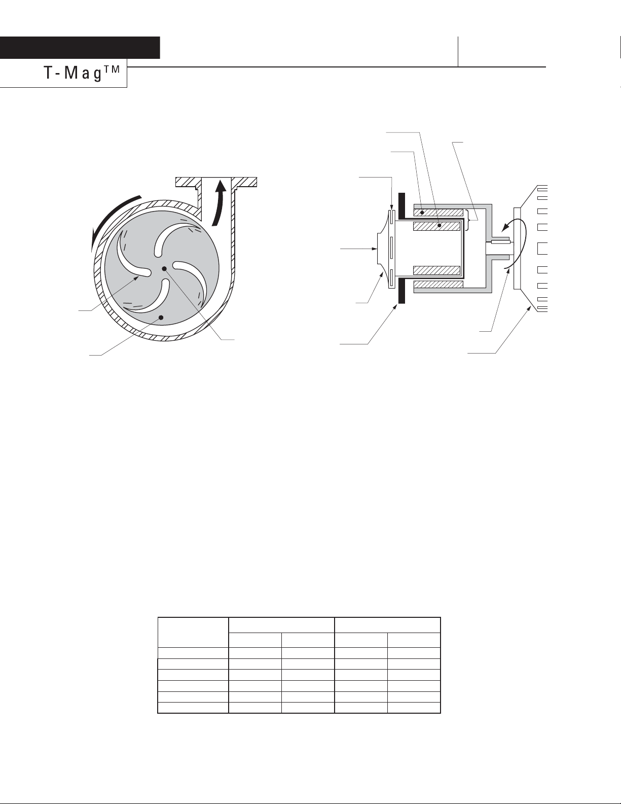
FIGURE 1: PUMP LIQUID END
Fluid is moved by a centrifugal pump through the use of centrifugal
force. Fluid is taken into the center of the impeller through the inlet
connection. Most centrifugal pumps prefer a positive inlet pressure
to prevent cavitation (lack of enough positive inlet pressure to
prevent liquid vaporization). This fluid is then caught by the vanes
of the impeller as it spins. This rotation of the fluid mechanically
by the vanes “throws” the fluid to the outside of the impeller and
toward the discharge port of the liquid end of the pump. This
mechanical movement of the fluid creates the discharge pressure
of the pump. Variables like inlet fluid supply pressure, impeller
diameter, motor horsepower and closed face versus open face all
effect the flow and pressure of the pump. Each of these variables
can be manipulated to achieve a desired flow and/or pressure.
FIGURE 2: PUMP MAGNETIC DRIVE
A magnetic drive pump uses a balanced magnetic field to create
the rotation of the fluid impeller. Unlike a traditional centrifugal
pump which has a direct drive connection between impeller and
motor, a mag-drive pump eliminates the direct drive mechanism
and replaces it with a magnetic field. An outer magnetic bell
housing is mounted on the end of the pump shaft. This outer bell
is aligned on the outside of the rear casing. The pump impeller
is connected to a smaller magnet assembly and rides on an
internal shaft and bushing assembly. (The liquid end parts are all
isolated within the fluid head of the pump without the need for a
mechanical seal.) The smaller magnet assembly is mounted within
the center of the magnetic field of the outer bell housing. Although
these two magnet assemblies are separated by a fluid barrier, the
magnetic fields are aligned. When the pump motor is started the
outer bell housing begins to rotate. As the outer bell rotates, the
rotating magnetic field effects the inner impeller magnet. As the
two magnets begin to turn together, the impeller begins turning
and displacing fluid.
Section 3
HOW IT WORKS—PUMP
$)3#(!2'%
)-0%,,%2
6!.%3
2/4!4)/.
&,/7
&,5)$
%.4%23
&2/-
#%.4%2
)..%2-!'.%43
/54%2-!'.%43
-/4/2
2/4!4)/.
-!'.%4)#&)%,$
2/4!4%3)-0%,,%2
2%!2
#!3).'
)-0%,,%2
&,5)$
).,%4
&,5)$%8)4
&2/-)-0%,,%2
5
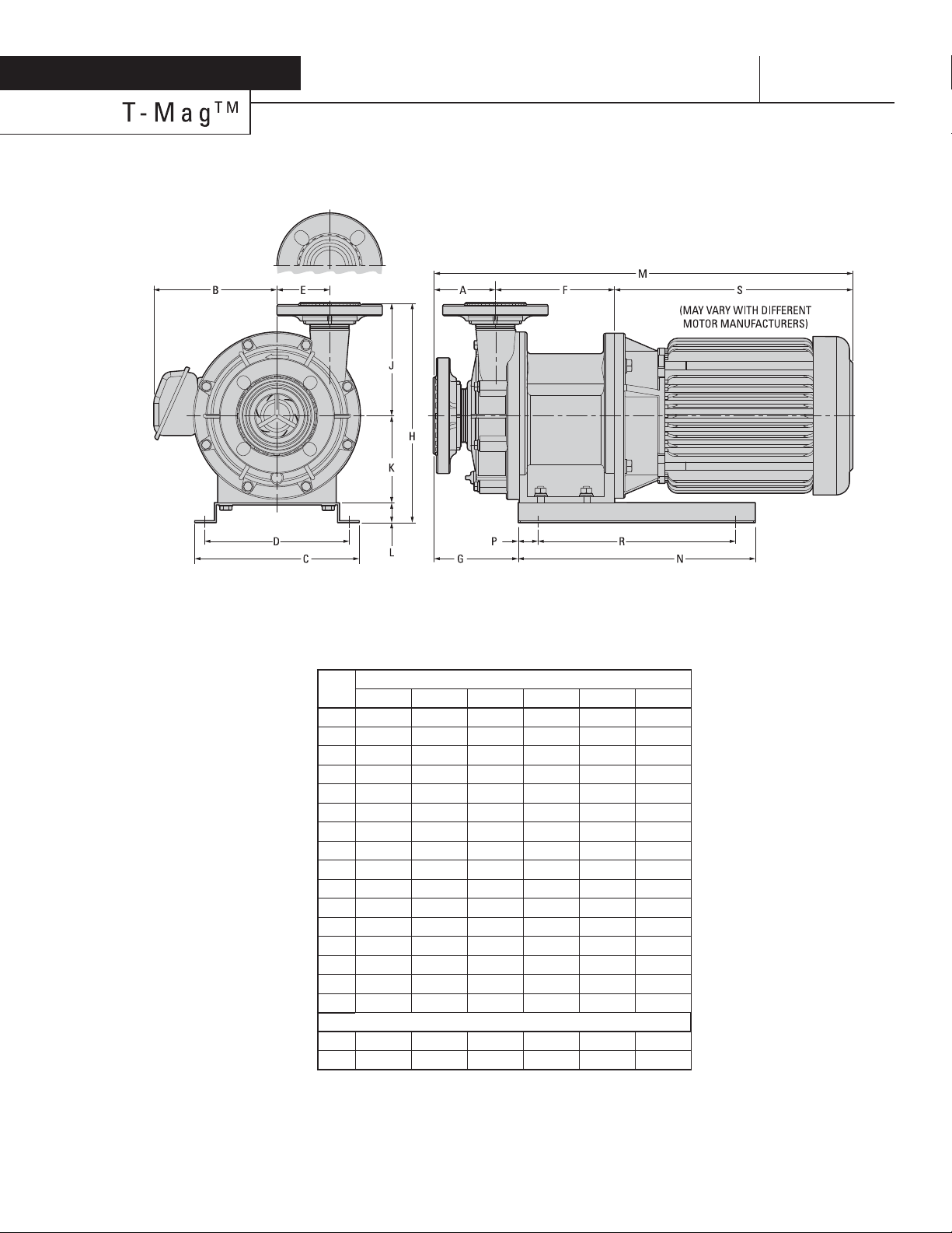
Section 4
DIMENSIONAL DRAWINGS
Note: The total length & weight of the pump will differ depending on the brand of the motor.
in
(mm)
Model Size
1/2 HP 1 HP 2 HP 3 HP 5 HP 5 HP
A
3.5 (89) 5.2 (131) 3.5 (90) 3.5 (90) 3.5 (90) 3.7 (94)
B
5.1 (130) 5.6 (142) 6.1 (155) 6.1 (155) 7.4 (187) 7.4 (187)
C
8.9 (225) 6.3 (160) 10.2 (260) 10.2 (260) 9.8 (250) 9.8 (250)
D
7.7 (195) 5.1 (130) 8.0 (204) 8.0 (204) 8.7 (220) 8.7 (220)
E
2.4 (60) 2.8 (72) 3.1 (80) 3.1 (80) 3.1 (80) 3.1 (80)
F
5.6 (142) 5.7 (146) 6.3 (160) 6.3 (160) 6.9 (175) 7.1 (180)
G
4.6 (116) 5.9 (150) 5.4 (138) 5.4 (138) 4.7 (119) 5.0 (128)
H
11.3 (286) 10.1 (256) 11.1 (281) 11.1 (281) 12.7 (323) 12.7 (323)
J
5.6 (141) 5.6 (141) 6.3 (161) 6.3 (161) 6.3 (161) 6.7 (171)
K
4.6 (118) 3.3 (85) 3.5 (90) 3.5 (90) 5.2 (132) 5.2 (132)
L
1.0 (25) 1.2 (30) 1.2 (30) 1.2 (30) 1.2 (30) 1.2 (30)
M
18.4 (467) 18.9 (481) 22.2 (564) 22.2 (564) 24.7 (627) 25.0 (636)
N
9.1 (230) 8.3 (210) 11.8 (300) 11.8 (300) 14.2 (360) 14.2 (360)
P
1.0 (25) 1.4 (35) 0.8 (20) 0.8 (20) 1.2 (30) 1.2 (30)
R
7.1 (180) 5.1 (130) 7.9 (200) 7.9 (200) 11.8 (300) 11.8 (300)
S
9.3 (236) 9.1( 232) 12.2 (311) 12.2 (311) 14.3 (362) 14.3 (362)
Flange (ANSI, DIN & JIS Combo)
In 1-1/2 (40) 1-1/2 (40) 2 (50) 2 (50) 2 (50) 2-1/2 (65)
Out 1-1/2 (40) 1-1/2 (40) 1-1/2 (40) 1-1/2 (40) 1-1/2 (40) 2 (50)
DIMENSIONS
6
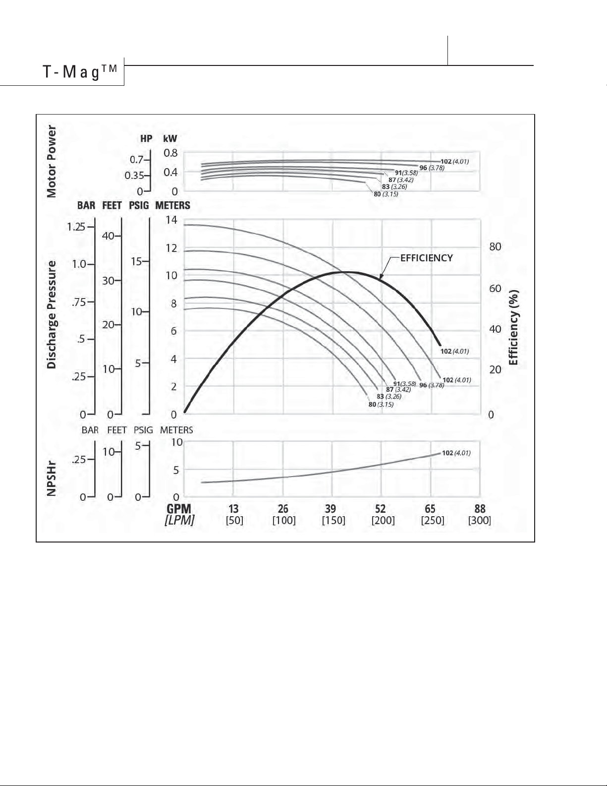
PERFORMANCE
1/2 HP (0.40 kW) - 50 Hz - 2900 RPM [TM4H]
Height
....................................
11.3" (286 mm)
Width
..................................
10.2" ( 260 mm)
Length
..................................
18.4" (467 mm)
Ship Weight
GF-PP
................................
40 lbs (18 kg)
CFR-ETFE
............................
42 lbs (19 kg)
Fluid Inlet
..............................
1-1/2" (38 mm)
Fluid Discharge
.....................
1-1/2" (38 mm)
Rated Point
......................
43 gpm (195 lpm)
All curves based upon pumping water
at sea level, specific gravity 1.0 ambient
temperature 20˚C (68˚F).
NOTE: Numbers shown to far right of all
performance lines denote the diameter of
the pump impeller [millimeters (inches)].
Consult factory for availability of impeller
trim sizes other than shown.
14.0 psig (0.96 bar)
7
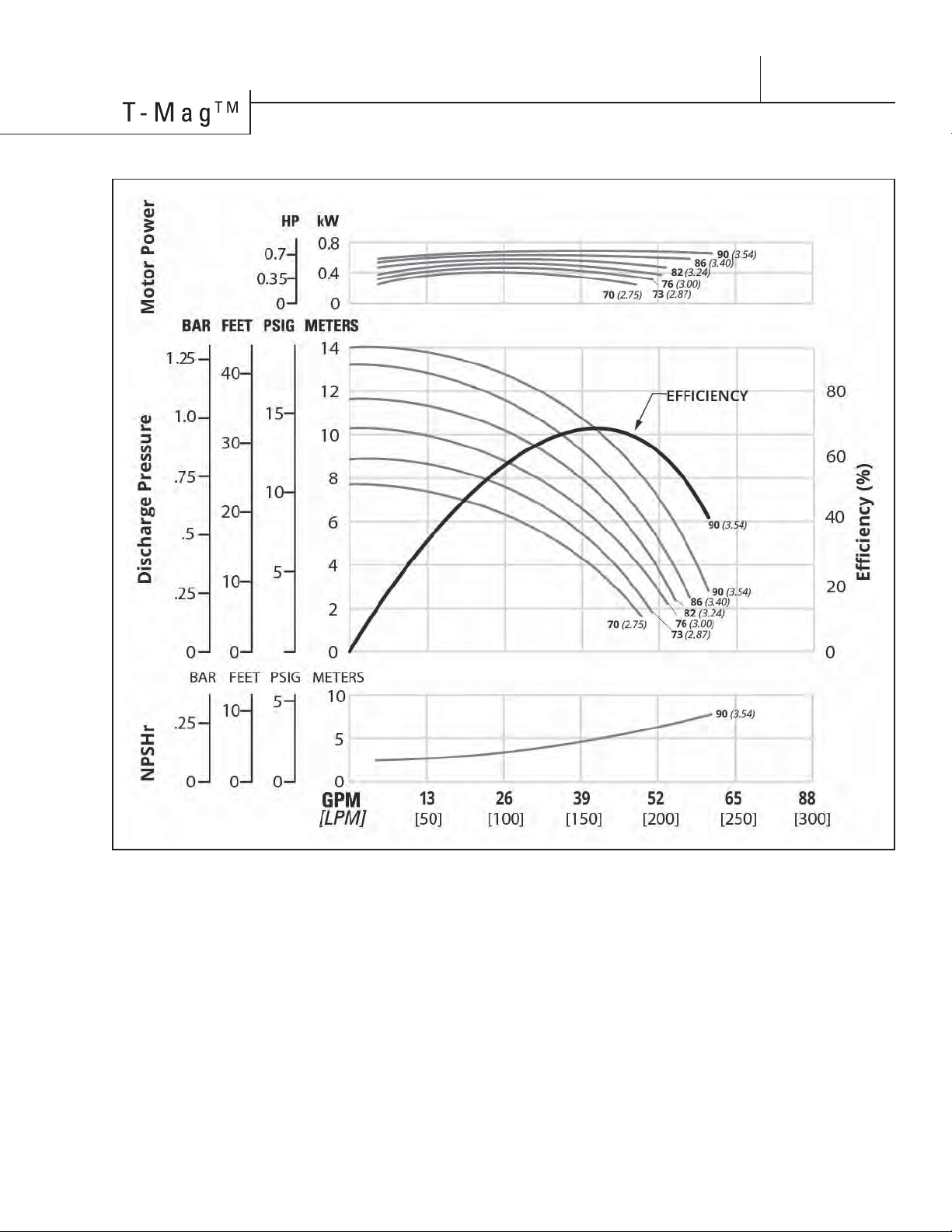
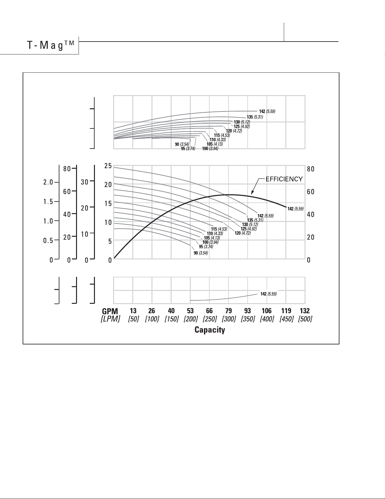
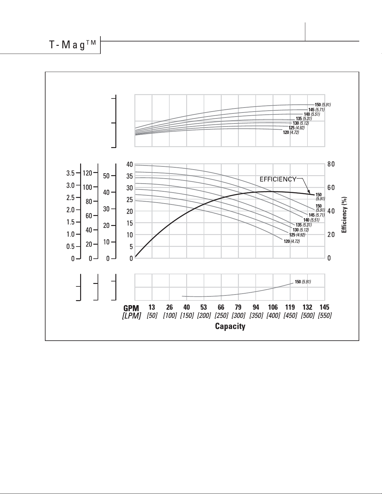
1/2 HP (0.40 kW) - 60 Hz - 3600 RPM [TM4H]
Height
....................................
11.3" (286 mm)
Width
..................................
10.2" ( 260 mm)
Length
..................................
18.4" (467 mm)
Ship Weight
GF-PP
................................
40 lbs (18 kg)
CFR-ETFE
............................
42 lbs (19 kg)
Fluid Inlet
..............................
1-1/2" (38 mm)
Fluid Discharge
.....................
1-1/2" (38 mm)
Rated Point
......................
4 3 gpm ( 195 l pm)
14.0 psig (0.96 bar)
All curves based upon pumping water
at sea level, specific gravity 1.0, ambient
temperature 20˚C (68˚F).
NOTE: Numbers shown to far right of all
performance lines denote the diameter of
the pump impeller [millimeters (inches)].
Consult factory for availability of impeller
trim sizes other than shown.
PERFORMANCE
8
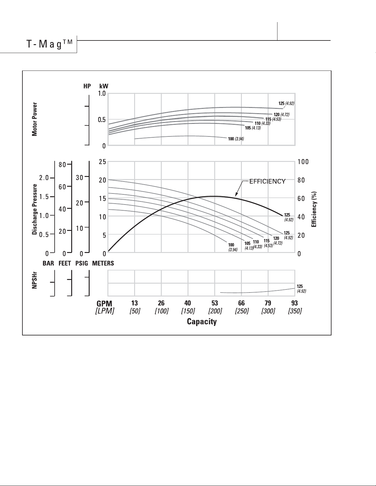
1 HP (0.75 kW) - 50 Hz - 2900 RPM [TM4K]
BAR FEET PSIG METERS
1
0.5
0
10
5
0
.25
0
10
0
5
0
Height
....................................
10.1" (256 mm)
Width
...................................
11.2" (284 mm)
Length
..................................
18.9" (481 mm)
Ship Weight
GF-PP
...............................
53 lbs (24 kg)
CFR-ETFE
............................
55 lbs (25 kg)
Fluid Inlet
..............................
1-1/2" (38 mm)
Fluid Discharge
.....................
1-1/2" (38 mm)
Rated Point
..................
45 gpm (204 lpm)
22.8 psig (1.57 bar)
All curves based upon pumping water
at sea level, specific gravity 1.0, ambient
temperature 20˚C (68˚F).
NOTE: Numbers shown to far right of all
performance lines denote the diameter of
the pump impeller in [millimeters (inches)]
Consult factory for availability of impeller
trim sizes other than shown.
P ERFORMANCE
9
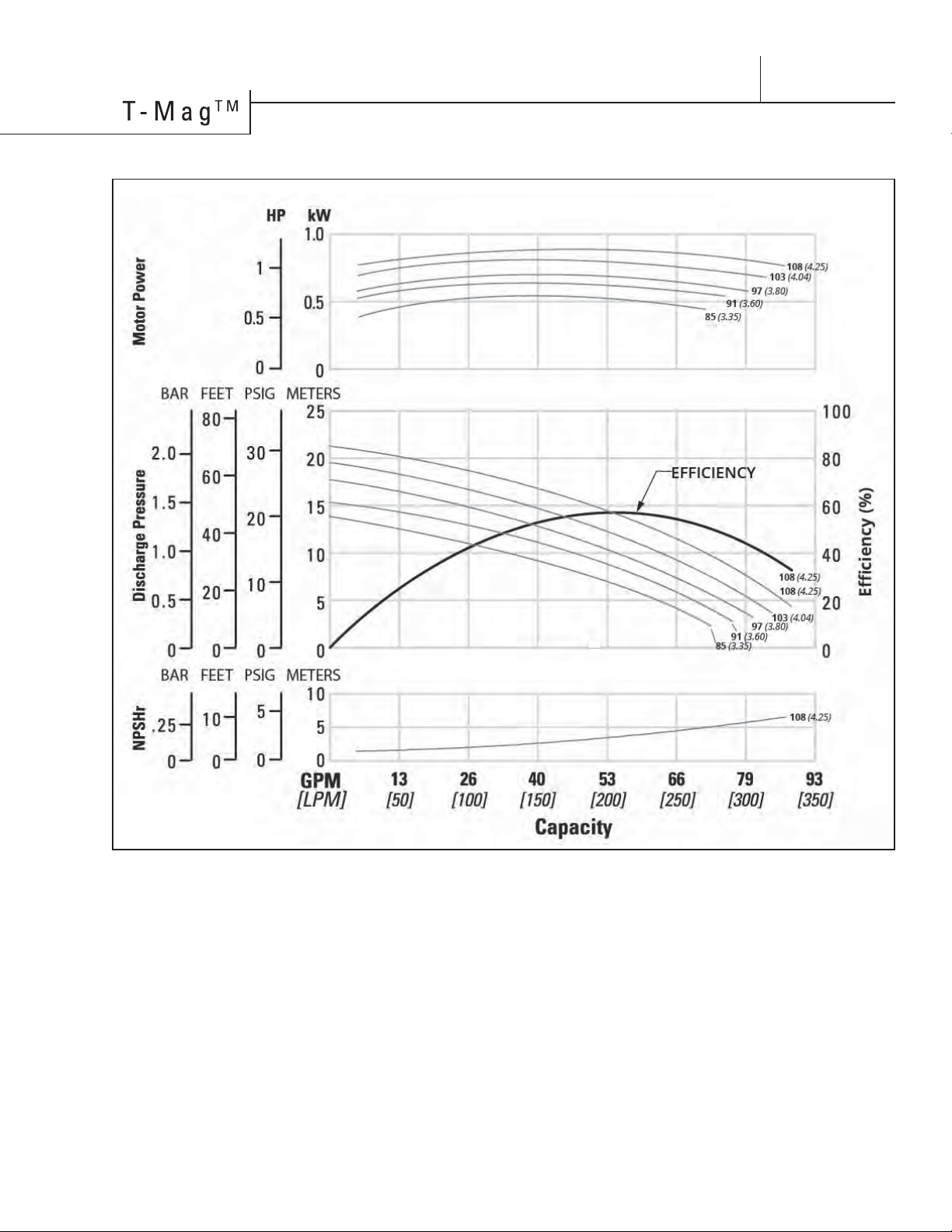
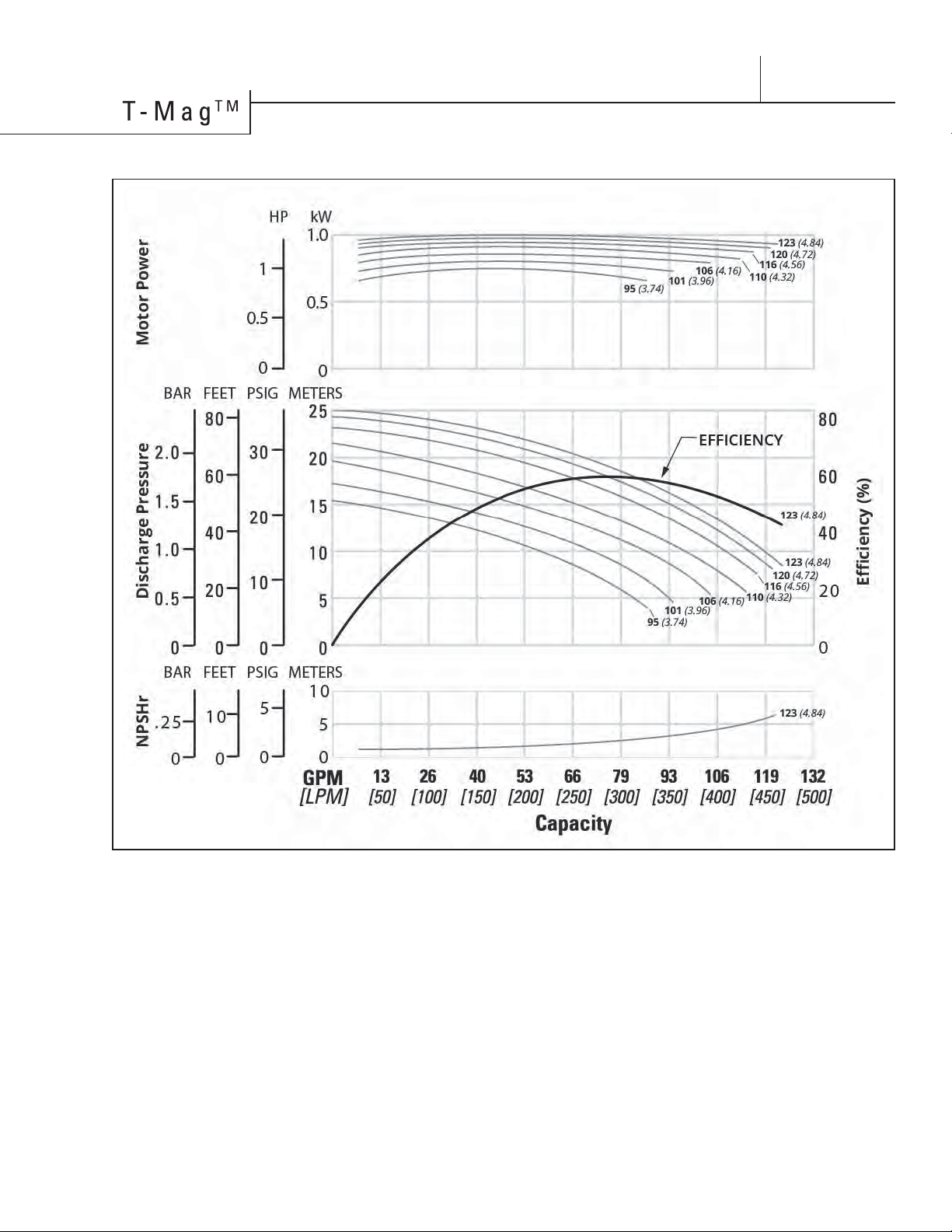
1 HP (0.75 kW) - 60 Hz - 3600 RPM [TM4K]
Height
....................................
10.1" (256 mm)
Width
...................................
11.2" (284 mm)
Length
..................................
18.9" (481 mm)
Ship Weight
GF-PP
...............................
53 lbs (24 kg)
CFR-ETFE
............................
55 lbs (25 kg)
Fluid Inlet
..............................
1-1/2" (38 mm)
Fluid Discharge
.....................
1-1/2" (38 mm)
Rated Point 53 gpm ( 240 lpm)
21.9 psig (1.51 bar)
All curves based upon pumping water
at sea level, specific gravity 1.0, ambient
temperature 20˚C (68˚F).
NOTE: Numbers shown to far right of all
performance lines denote the diameter of
the pump impeller in [millimeters (inches)].
Consult factory for availability of impeller
trim sizes other than shown.
PERFORMANCE
........................
10
Height
....................................
11.1" (281 mm)
Width
......................................
12.0" (305 mm)
Length
.................................
22.2" (564 mm)
Ship Weight
GF-PP
................................
77 lbs (35 kg)
CFR-ETFE
............................
79 lbs (36 kg)
Fluid Inlet
....................................
2" (51 mm)
Fluid Discharge
........................
1-1/2" (38 mm)
Rated Point
...................
75 gpm (340 lpm)
25 psig (1.72 bar)
All curves based upon pumping water
at sea level, specific gravity 1.0, ambient
temperature 20˚C (68˚F).
NOTE: Numbers shown to far right of all
performance lines denote the diameter of
the pump impeller in [millimeters (inches)]
Consult factory for availability of impeller
trim sizes other than shown.
2 HP (1.5 kW) - 50 Hz - 2900 RPM [TM6L]
BAR FEET PSIG METERS
Discharge Pressure
(ɝFLHQF\
BAR FEET PSIG METERS
.25
0
10
0
5
0
2
1
0
HP kW
NPSHr Motor Power
10
5
0
2
1
0
PERFORMANCE
11
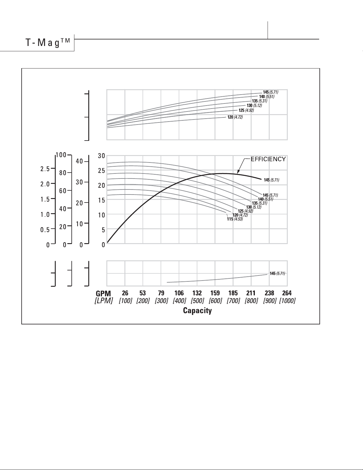
Height
....................................
11.1" (281 mm)
Width
......................................
12.0" (305 mm)
Length
.................................
22.2" (564 mm)
Ship Weight
GF-PP
................................
77 lbs (35 kg)
CFR-ETFE
............................
79 lbs (36 kg)
Fluid Inlet
....................................
2" (51 mm)
Fluid Discharge
........................
1-1/2" (38 mm)
Rated Point
...................
85 gpm (386 lpm)
26 psig (1.79 bar)
All curves based upon pumping water
at sea level, specific gravity 1.0, ambient
temperature 20˚C (68˚F).
NOTE: Numbers shown to far right of all
performance lines denote the diameter of
the pump impeller in [millimeters (inches)].
Consult factory for availability of impeller
trim sizes other than shown.
2 HP (1.50 kW) - 60 Hz - 3600 RPM [TM6L]
PERFORMANCE

12
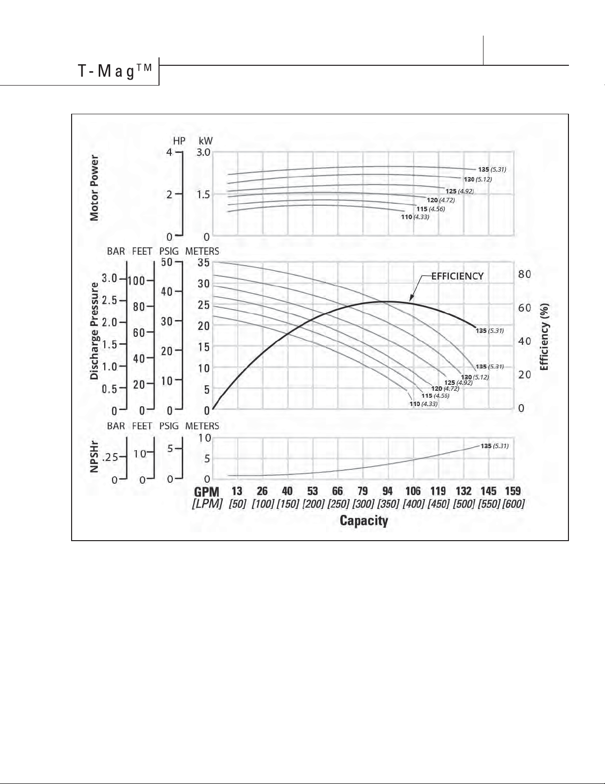
3 HP (2.2 kW) - 50 Hz - 2900 RPM [TM6M]
BAR FEET PSIG METERS
Discharge Pressure
(ɝFLHQF\
80
60
40
20
0
BAR FEET PSIG METERS
.25
0
10
0
5
0
3.0
1.5
0
HP kW
NPSHr Motor Power
10
5
0
4
2
0
PERFORMANCE
Height
....................................
11.1" (281 mm)
Width
......................................
12.0" (305 mm)
Length
.................................
22.2" (564 mm)
Ship Weight
GF-PP
................................
82 lbs (37 kg)
CFR-ETFE
............................
84 lbs (38 kg)
Fluid Inlet
....................................
2" (51 mm)
Fluid Discharge
........................
1-1/2" (38 mm)
Rated Point
...................
77 gpm (350 lpm)
36.7 psig (2.53 bar)
All curves based upon pumping water
at sea level, specific gravity 1.0, ambient
temperature 20˚C (68˚F).
NOTE: Numbers shown to far right of all
performance lines denote the diameter of
the pump impeller in [millimeters (inches)]
Consult factory for availability of impeller
trim sizes other than shown.
13
3 HP (2.20 kW) - 60 Hz - 3600 RPM [TM6M]
PERFORMANCE
Height
....................................
11.1" (281 mm)
Width
......................................
12.0" (305 mm)
Length
.................................
22.2" (564 mm)
Ship Weight
GF-PP
................................
82 lbs (37 kg)
CFR-ETFE
............................
84 lbs (38 kg)
Fluid Inlet
....................................
2" (51 mm)
Fluid Discharge
........................
1-1/2" (38 mm)
Rated Point
...................
90 gpm (409 lpm)
37.3 psig (2.57 bar)
All curves based upon pumping water
at sea level, specific gravity 1.0, ambient
temperature 20˚C (68˚F).
NOTE: Numbers shown to far right of all
performance lines denote the diameter of
the pump impeller in [millimeters (inches)].
Consult factory for availability of impeller
trim sizes other than shown.
14
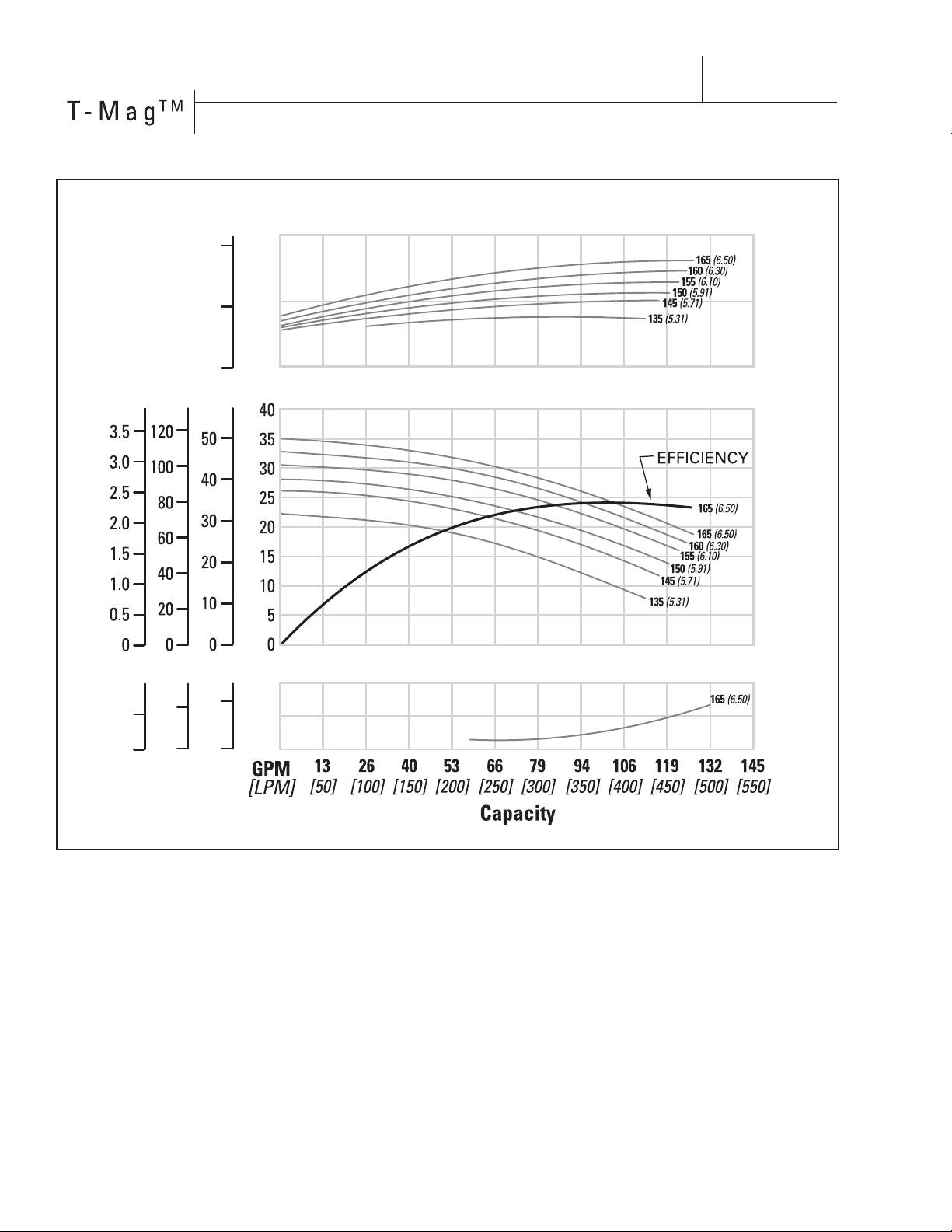
5 HP (3.7 kW) - 50 Hz - 2900 RPM [TM6N]
BAR FEET PSIG METERS
Discharge Pressure
(ɝFLHQF\
80
60
40
20
0
4.0
2.0
0
HP kW
NPSHr Motor Power
5
2.5
0
10
5
0
BAR FEET PSIG METERS
.25
0
10
0
5
0
PERFORMANCE
Height
...................................
12.7" (323 mm)
Width
......................................
13.3" (337 mm)
Length
..................................
24.7" (627 mm)
Ship Weight
GF-PP
..............................
117 lbs (53 kg)
CFR-ETFE
...........................
119 lbs (54 kg)
Fluid Inlet
....................................
2" (51 mm)
Fluid Discharge
......................
1-1/2" (38 mm)
Rated Point
..................
100 gpm (454 lpm)
35 psig (2.41 bar)
All curves based upon pumping water
at sea level, specific gravity 1.0, ambient
temperature 20˚C (68˚F).
NOTE: Numbers shown to far right of all
performance lines denote the diameter of
the pump impeller in [millimeters (inches)]
Consult factory for availability of impeller
trim sizes other than shown.
15
5 HP (3.7 kW) - 60 Hz - 3600 RPM [TM6N]
BAR FEET PSIG METERS
Discharge Pressure
4.0
2.0
0
HP kW
NPSHr Motor Power
5
2.5
0
10
5
0
BAR FEET PSIG METERS
.25
0
10
0
5
0
PERFORMANCE
Height
...................................
12.7" (323 mm)
Width
......................................
13.3" (337 mm)
Length
..................................
24.7" (627 mm)
Ship Weight
GF-PP
..............................
117 lbs (53 kg)
CFR-ETFE
...........................
119 lbs (54 kg)
Fluid Inlet
....................................
2" (51 mm)
Fluid Discharge
......................
1-1/2" (38 mm)
Rated Point
..................
105 gpm (477 lpm)
40.0 psig (2.75 bar)
All curves based upon pumping water
at sea level, specific gravity 1.0, ambient
temperature 20˚C (68˚F).
NOTE: Numbers shown to far right of all
performance lines denote the diameter of
the pump impeller [millimeters (inches)]
Consult factory for availability of impeller
trim sizes other than shown.
16
5 HP (3.7 kW) - 50 Hz - 2900 RPM Oversize Inlet [TM10N]
BAR FEET PSIG METERS
Discharge Pressure
(ɝFLHQF\
80
60
40
20
0
4.0
2.0
0
HP kW
NPSHr Motor Power
5
2.5
0
10
5
0
BAR FEET PSIG METERS
.25
0
10
0
5
0
PERFORMANCE
Height
...................................
13.1" (333 mm)
Width
...................................
13.7" (347 mm)
Length
.................................
25.0" (636 mm)
Ship Weight
GF-PP
..............................
117 lbs (53 kg)
CFR-ETFE
..........................
119 lbs (54 kg)
Fluid Inlet
.............................
2-1/2" (64 mm)
Fluid Discharge
..........................
2" (51 mm)
Rated Point
...................
34.0 psig (2.34 bar)
All curves based upon pumping water
at sea level, specific gravity 1.0, ambient
temperature 20˚C (68˚F).
NOTE: Numbers shown to far right of all
performance lines denote the diameter of
the pump impeller in [millimeters (inches)]
Consult factory for availability of impeller
trim sizes other than shown.
150 gpm (681 lpm)
17
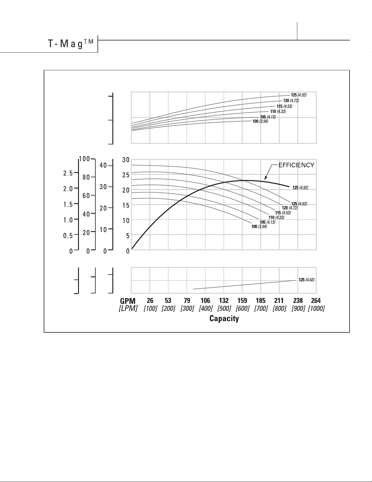
Height
...................................
13.1" (333 mm)
Width
...................................
13.7" (347 mm)
Length
.................................
25.0" (636 mm)
Ship Weight
GF-PP
..............................
117 lbs (53 kg)
CFR-ETFE
..........................
119 lbs (54 kg)
Fluid Inlet
.............................
2-1/2" (64 mm)
Fluid Discharge
..........................
2" (51 mm)
Rated Point
...................
33.0 psig (2.34 bar)
All curves based upon pumping water
at sea level, specific gravity 1.0, ambient
temperature 20˚C (68˚F).
NOTE: Numbers shown to far right of all
performance lines denote the diameter of
the pump impeller [millimeters (inches)]
Consult factory for availability of impeller
trim sizes other than shown.
PERFORMANCE
5 HP (3.7 kW) - 60 Hz - 3600 RPM Oversize Inlet [TM10N]
BAR FEET PSIG METERS
Discharge Pressure
(ɝFLHQF\
80
60
40
20
0
NPSHr
4.0
2.0
0
HP kW
Motor Power
5
2.5
0
10
5
0
BAR FEET PSIG METERS
.25
0
10
0
5
0
159 gpm (722 lpm)

13
Section 6
SUGGESTED INSTALLATION
T-MAG™ pumps are designed to meet the performance
requirements of even the most demanding pumping
applications. They have been designed and manufactured
to the highest standards and are available in a variety of
liquid path materials to meet your chemical resistance
needs. Refer to the performance section of this manual
for an in-depth analysis of the performance characteristics
of your pump. The suction pipe size should be at least
the equivalent or larger than the diameter size of the
suction inlet on your T-MAG™ pump. The suction hose/
pipe must be non-collapsible. Discharge piping should
also be the equivalent or larger than the diameter of the
pump discharge which will help reduce friction losses. It
is critical that all ttings and connections are airtight to
reduce the rist of cavitation which may damage the pump.
INSTALLATION: Months of careful planning, study, and
selection eorts can result in unsatisfactory pump
performance if installation details are left to chance.
Premature failure and long term dissatisfaction can be
avoided if reasonable care is exercised throughout the
installation process.
LOCATION: Noise, safety, and other logistical factors
usually dictate where equipment will be situated on the
production oor. Multiple installations with conicting
requirements can result in congestion of utility areas,
leaving few choices for additional pumps. Within the
framework of these and other existing conditions, every
pump should be located in such a way that the 8 key
factors are balanced against each other to maximum
advantage.
ACCESS: First of all, the location should be accessible. If
it’s easy to reach the pump, maintenance personnel will
have an easier time carrying out routine inspections and
adjustments. Should major repairs become necessary,
ease of access can play a key role in speeding the repair
process and reducing total downtime.
ELECTRICAL SUPPLY: Every pump location should have
all power lines, conduit and switches mounted in such
a way as to avoid any risk or hazard to the user or work
area. Keep in mind that while pumping some uids it
is required to ground the pump to prevent discharge of
any static buildup. For best results, ensure a licensed
professional performs any necessary installation work.
PUMP INLET: To optimize pump life it is important to
install the pump in a position that will ensure a constant
supply of process uid. Running the unit dry will cause
cavitation which could result in unnecessary vibration.
This vibration can result in internal component damage
that could diminish the life of the pump. Also, although
the pump is designed to run dry without damage in the
carbon / ceramic conguration, running dry on a regular
basis can shorten the overall mean time between failure
(MTBF) of the pump.
CONTROLS: All pumps should be outtted with the
appropriate safety shut o and controls to meet the
local, state or federal requirements for the application in
the area the pump is being used. To better understand
the performance of the pump it is recommended that
gauges be placed on the inlet and discharge lines of the
pump, isolation gauges be installed for isolation and
repairs and a ow meter be used to monitor the pump’s
performance over time.
PUMP DISCHARGE: Be sure that the discharge
capabilities of the pump meet the required pressure to
overcome the friction loss across the discharge piping,
lters and valving. Do not close the downstream
isolation valve of the pump while in operation. Doing so
will cause the pump head to overheat and may damage
the internals of the pump.
PIPING: Final determination of the pump site should not
be made until the piping challenges of each possible
location have been evaluated. The impact of current
and future installations should be considered ahead of
time to make sure that inadvertent restrictions are not
created for any remaining sites.
The best choice possible will be a site involving
the shortest and straightest hook-up of suction and
discharge piping. Unnecessary elbows, bends, and
ttings should be avoided. Pipe sizes and type should
be selected to keep friction losses within practical
limits. All piping should be supported independently of
the pump. In addition, the piping should be aligned to
avoid placing stress on the pump ttings.
Flexible hose can be installed to aid in absorbing the
forces created by the natural vibration of the pump. If the
pump is to be bolted down to a solid location, a mounting
pad placed between the pump and the foundation will
assist in minimizing pump vibration.
When pumps are installed in applications involving
ooded suction or suction head pressures, a gate valve
should be installed in the suction line to permit closing
of the line for pump service.
SUBMERSIBLE APPLICATIONS: T-MAG™ pumps can
not be submerged for use.
T-MAG™ PUMPS ARE CAPABLE OF PASSING SOLIDS
BELOW 50 (microns), ALTHOUGH ANY SOLIDS WITHIN
THE PROCESS STREAM OF A T-MAG™ PUMP COULD
WEAR CRITICAL COMPONENTS.
This wear will diminish performance or cause failure
of the pump. Standard carbon tted T-MAG™ Mag-
Drive pumps are suited for limited dry run conditions
only. Other materials such as Rulon® and SSIC tted
pumps are not suitable for dry run conditions.
This manual suits for next models
3
Popular Water Pump manuals by other brands


Gormann-Rupp Pumps
Gormann-Rupp Pumps 82E-GX240 Installation, operation, and maintenance manual with parts list

McKINLEY
McKINLEY T34 Operation manual

GORMAN-RUPP
GORMAN-RUPP AMT 5586-H6 manual

Clarke
Clarke IVP13A Operating & maintenance instructions

KSB
KSB Hya-Rain Installation & operating manual

Speck pumpen
Speck pumpen V Series operating instructions

Grundfos
Grundfos SPRING N Series Service instructions

Pontec
Pontec PondoGarden 3200 operating instructions

Torishima Pump
Torishima Pump ETA-N Operation and maintenance manual

Grundfos
Grundfos Liftaway B Installation and operating instructions

Varian
Varian Turbo-V 2K-G instruction manual

Whale
Whale Supersub Series Installation guides