English (GB)
5
English (GB) Installation and operating instructions
Original installation and operating instructions
CONTENTS
Page
1. General description
Grundfos Liftaway B 40-1 for underfloor installation
is a compact mini lifting station consisting of a tank
and a wastewater pump, type Unilift KP 150, Unilift
KP 250 or Unilift AP12, with level switch for
automatic start/stop. The lifting station is designed
for the pumping of wastewater from wash basins,
washing machines, showers and floor drains. The
Liftaway B 40-1 can also be used for the collection
and pumping of rain water.
The variable height of the tank, which is installed
under the floor, makes it easy to adjust the tank to
floor level.
These instructions apply to the Liftaway B 40-1 tank
and installation kit only. See also the installation and
operating instructions supplied with the pump.
1.1 Applications
The Liftaway B 40-1 in combination with the Unilift
KP 150, Unilift KP 250 or Unilift AP12 is designed for
the pumping of wastewater from wash basins,
washing machines, showers and floor drains where
the wastewater cannot be led directly to the sewer by
means of a natural downward slope.
The Liftaway B 40-1 must not be used for the
pumping of sewage water from toilets.
The lifting station is typically used:
• as draining well for the collection of drainage and
surface water,
• the pumping of wastewater from basements and
laundry rooms below sewer level.
1.2 Pumped liquids
Wastewater, not containing solid particles.
Liquid temperature: Maximum 70 °C.
The tank is resistant to weak acids with pH values of
4 to 10.
Wastewater containing fat must not be discharged
into the tank.
See also installation and operating instructions for
the pump.
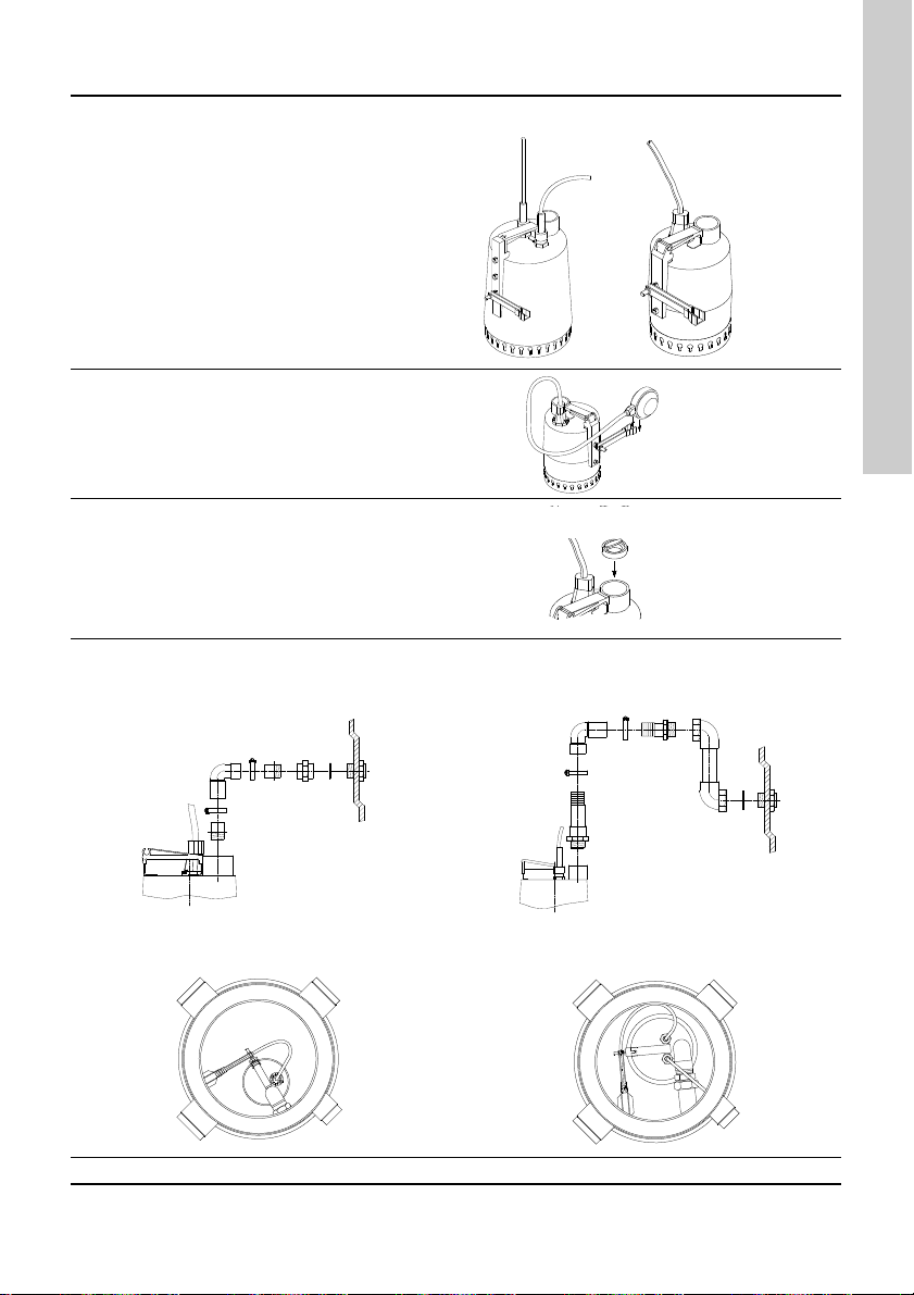
2. Function
Wastewater from the connected units is discharged
into the lifting station. The pump starts and stops by
means of the level switch, depending on liquid level
in tank.
The wastewater is pumped through the discharge
pipe to the main sewer line.
3. Technical data
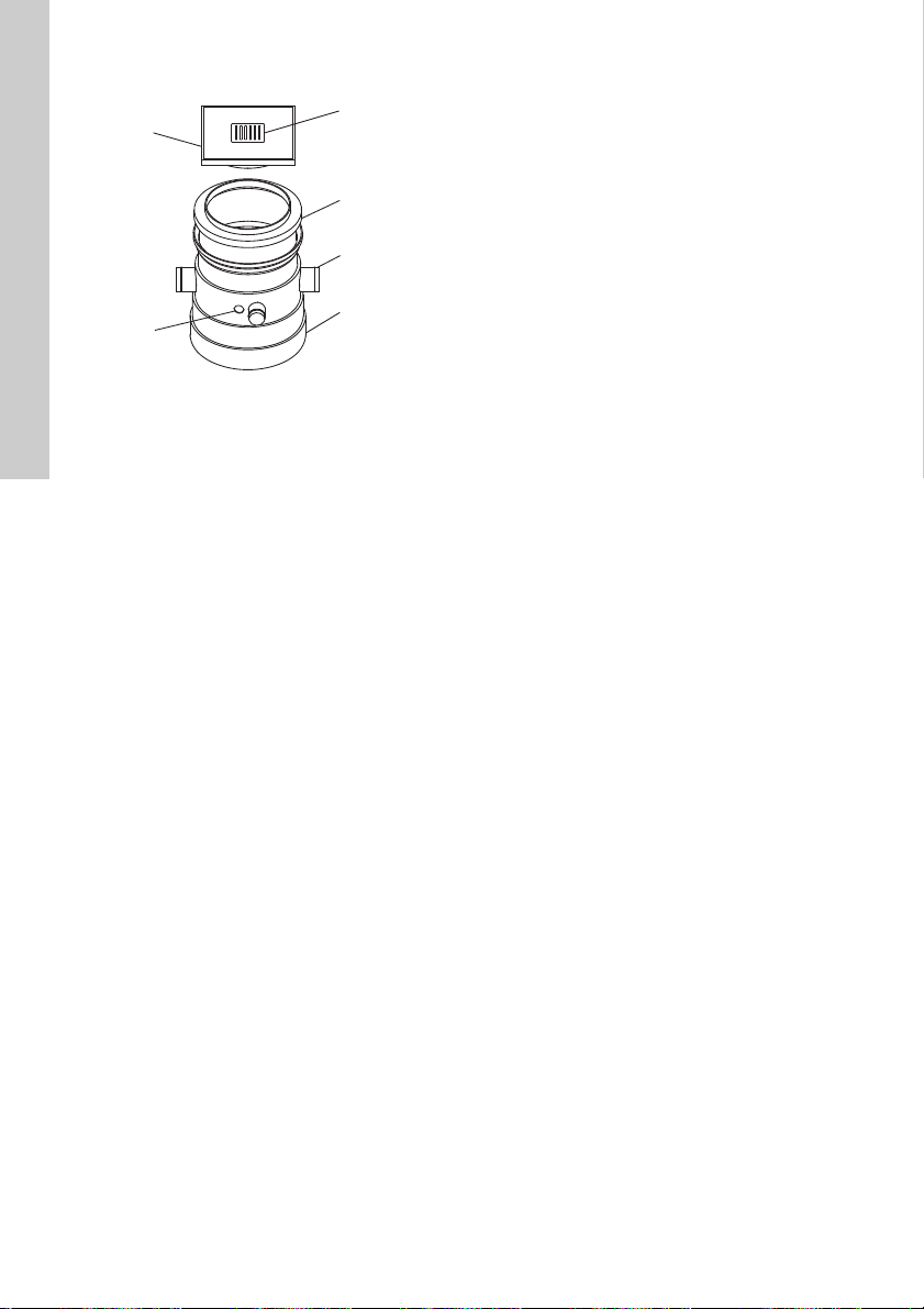
4. Components
1. Plastic cover. The cover can be turned to any
position.
2. Plastic tank.
3. Stainless steel drain grating with water seal.
4. 3 inlet connections (DN 100) and 1 connection for
venting and/or cable entry (DN 70).
5. Hole for discharge connection.
6. Telescopic part for height adjustment. An
additional telescopic part is available. This part
gives a maximum height of 795 mm.
7. Kit including non-return valve and various fittings
required for pump connection.
1. General description 5
1.1 Applications 5
1.2 Pumped liquids 5
2. Function 5
3. Technical data 5
4. Components 5
5. Dimensions 6
6. Installation of tank 6
7. Mounting the pump in tank 7
8. Startup and venting 8
9. Maintenance 8
Warning
Prior to installation, read these installation
and operating instructions. Installation and
operation must comply with local
regulations and accepted codes of good
practice.
Discharge connection: R 1 1/4.
Inlet connections: 3 x DN 100.
Connection for venting
and/or cable entry: DN 70.
Technical data for pump: See pump instructions.
TM01 1016 3597