Instruction and Operating Manual
TA-05KB-SMD & TA-1K-SMD
We reserve the right to correct technical and printing errors
4
5 Functional tests and preliminary adjustments before operating
a) Armature feedback control (UA -control)
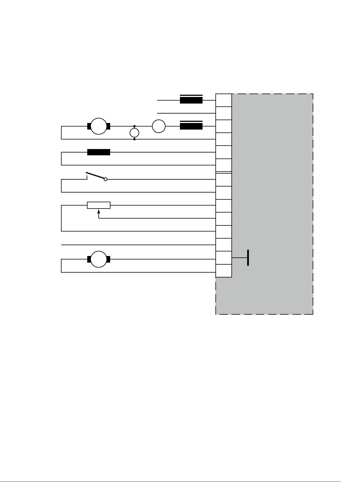
1. Check all connections with an Ohmmeter for grounds.
2. Install resistor R8= 150k ohm (is built-in at delivery status at armature regulation).
At tachometer regulation please demount.
3. Check if your a.c. line voltage corresponds to the marking on the unit.
4. Check the resistance of the field winding between terminals 5 and 6. Minimum resistance should
read 400 Ohm (it might be necessary to reverse the polarity of the Ohmmeter).
5. Potentiometer P1, Min. speed, set fully clockwise
Potentiometer P2, Acceleration rate, set fully clockwise
Potentiometer P4, IxR-compensation, set fully counter clockwise
6. Switch on AC line voltage, the green diode LED 2 must now light up.
7. Switch on drive control, the yellow LED 1 (control release) lights up.
8. Measure field voltage between terminals 5 (+F) and 6 (-F) with a Multimeter (should read 210VDC).
Now measure voltage of potentiometer between terminals 9 and 11 (should read +15VDC). When
turning speed potentiometer clockwise, the armature voltage will rise and the motor speed will
increase. Turn the speed potentiometer fully clockwise and adjust the armature voltage (motor
speed) with P3 (max. speed) for the requested maximum value. Now turn the speed potentiometer
fully counter clockwise, the output voltage must drop back to 0 V and the potentiometer P1 (min.
speed) can now be adjusted for the requested minimum speed.
9. Adjust the I x R compensation with potentiometer P4. Check for approximate equal speed with
and without motor load in the lower speed range. When the potentiometer is turned clockwise, the
speed under load will increase. If the compensation control is set to high, the drive will become
unstable.
10. Current limit. For checking the current limit the field must be disconnected and the motor must be
blocked1). Preset reference signal (speed) and adjust the requested current with potentiometer P5
(this must cause the red diode LED 3 „Current Limit“ to light up). This adjustment must be perfor-
med within 10 sec. otherwise damage to the commutator is possible.
11. Acceleration rate. Adjust the requested acceleration time with potentiometer P2. Turning this poten-
tiometer clockwise will decrease the acceleration time.
1) A short-circuit of the connections from the field, never the connection of the device!
b) Tachometer feedback control
1. Check all connections with an Ohmmeter for grounds. Remove resistor R8.
2. Install resistor R36. Calculation of R36 as follows:
R36 in (kOhm) = Tachometer voltage (V). at rated speed x 3 -110
3. For all further adjustments refer to the adjustments as explained for the armature feedback control,
however P4 (1 x R compensation) must be set fully counter clockwise.