Taico TK4800 User manual

1
TK4800 (51.2V 100Ah)
Lithium Iron Phosphate Battery
User Manual

2
Directory
Directory..................................................................................................... 2
1. Notes.......................................................................................................3
2. Introduction............................................................................................4
3. Characteristics...................................................................................... 4
4. Parameter Specifications.................................................................... 5
4.1 Dimensions...................................................................................... 5
4.2 Battery Parameters.........................................................................5
4.3 Interface Definitions........................................................................6
5. LiFePO4 Battery Safety Operating Guidelines............................... 9
5.1 Application Schematic....................................................................9
5.2 Tools..................................................................................................9
5.3 Security equipment.........................................................................9
6 Installation.............................................................................................10
6.1 Installation location.......................................................................10
6.2 Installation...................................................................................... 10
7. Maintenance Precautions ............................................................. 11
8. FAQ Analysis and Solutions .........................................................11

3
1. NOTES
Attention!
(1)It is important and necessary to read the user manual carefully before
installing or using the battery. The safety precautions mentioned in this manual
do not represent all safety matters to be observed and only complement all
safety precautions;
(2)When installing, operating and maintaining equipment, local safety
regulations shall be observed and followed;
(3)Do not wear any conductive objects such as watches, bracelets, and
rings when installing, operating and maintaining equipment;
(4)If the battery is stored for long before installation, it needs to be charged
and discharged every six months, and the battery charge percentage shall not
be less than 70%;
(5)If the battery is fully discharged, it should be charged within 12 hours;
(6)Before maintenance, batteries and equipment must be cut off firstly;
(7)Do not use cleaning solvents to clean batteries;
(8)Do not expose batteries to flammable or irritating chemicals or vapors;
(9)Do not connect batteries directly to photovoltaic solar wires;
(10)Our company is not responsible for any loss caused by violation of
general safety operation requirements or violation of design, production and
use of equipment safety standards.
Warning!
1.1 Before Installation
1.1.1 After unpacking, please check the product and packing list first, if the
product is damaged or missing any parts, please contact the seller;
1.1.2 Before installation, cut off the power supply and ensure the battery is
off;

4
1.1.3 Wiring must be correct, do not mistake positive(+) and negative(-)
cables, and ensure the external devices are not short-circuited;
1.1.4 Direct connection of batteries and AC power is prohibited;
1.1.5 Battery protection system is designed for 48V DC, no series
connections allowed;
1.1.6 Please ensure that the electrical parameters of the battery system
are compatible with the relevant equipment;
1.1.7 Keep the battery away from water and fire.
1.2 Usage
1.2.1 If the battery system needs to be moved or repaired, the power must
be cut off and the battery completely stops working;
1.2.2 It’s prohibited for connecting this battery to other different type of
batteries;
1.2.3 It’s prohibit for connecting this battery with any faulty or incompatible
devices;
1.2.4 When fire occurs, only dry powder fire extinguishers can be used,
liquid fire extinguishers are prohibited;
1.2.5 Do not disassemble batteries privately;
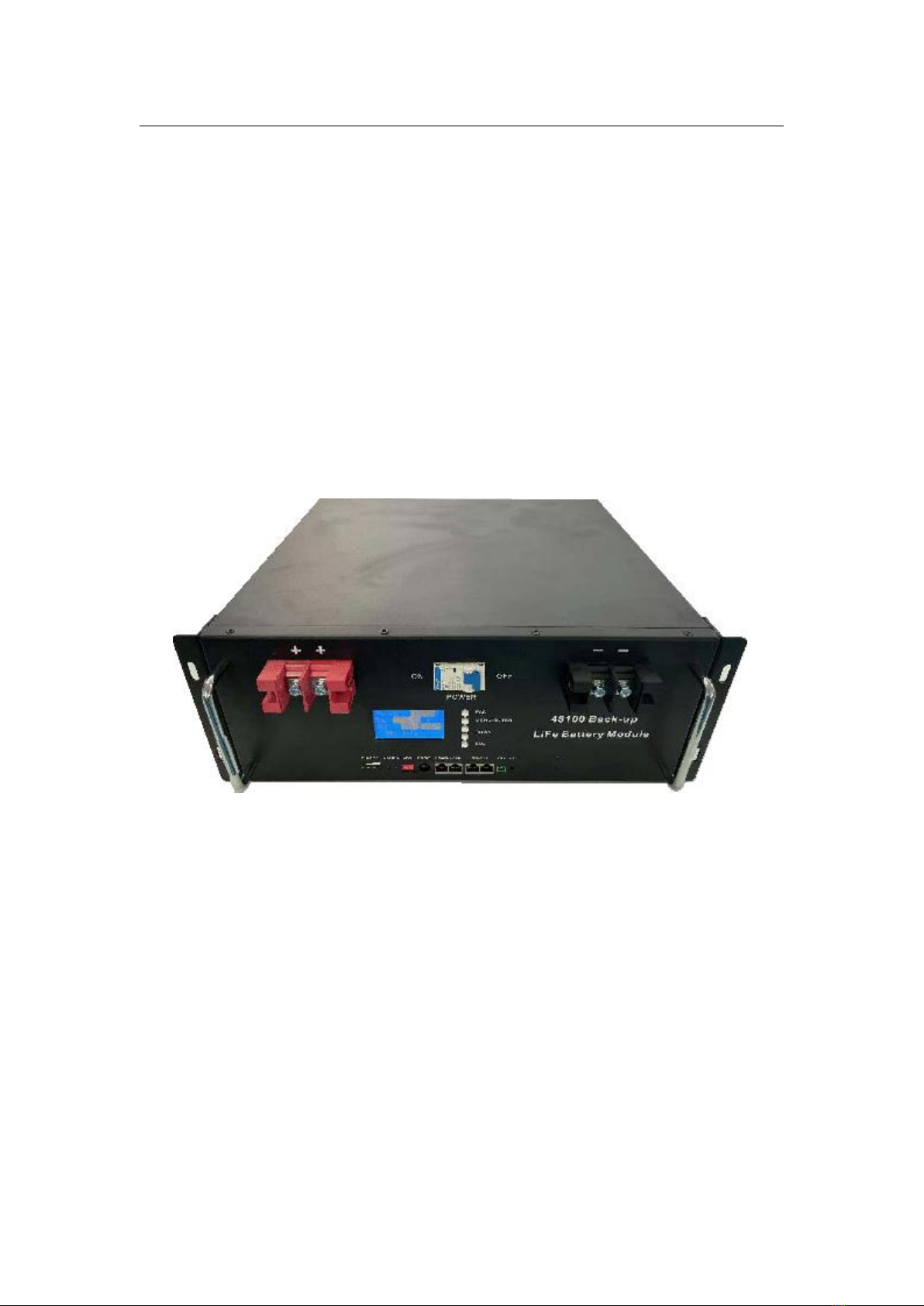
2. Introduction
This battery is a new type of energy storage product, which can be used to
provide reliable power supply for various equipment and systems. It is
especially suitable for applications with large power, limited installation space,
limited bearing capacity and long life. Battery built-in BMS -battery
management system, battery voltage, current, temperature and other
information management and monitoring. In addition, the battery pack can
balance the charge and discharge of the battery to prolong the cycle life.
Multiple battery packs can be parallel to expand capacity and power, parallel to
expand capacity and longer power support time requirements.

5
3. Characteristics
Environmental protection and pollution-free: the whole battery module
using materials are non-toxic, pollution-free;
long safety life: the core cathode material of battery module is made of
LiFeOP4, good safety performance and long service life;
Protection function: battery management system can protect battery
module over discharge, over charge, over current and high / low temperature;
Equilibrium function: the battery management system has its own passive
equalization, can balance the battery module each single string core;
Expansion: flexible configuration, multiple battery modules can be parallel
expansion capacity, applicable to different standby time requirements;
Low power consumption: the battery has the function of automatic
dormancy, when no live equipment is connected, it can enter the low power
state by itself and reduce the self-loss;
No memory: no memory effect, shallow charge and discharge
performance is excellent;
Wide temperature range: working temperature range-20~70, charge 0~60,
discharge-20~70, good discharge performance and cycle life,
Portable: Small, lightweight, standard 19-inch embedded module easy to
install and maintain

6
4. Parameter Specifications
4.1 Dimensions
4.2 Battery Parameters
Project
Parameters
Model
TK4800 (51.2V100Ah)
Nominal voltage
51.2V
Nominal capacity
100Ah
Combination mode
16 Series
Dimensions W×D×H (mm)
482×400×177
Weight
About 45KG
Working voltage
43.2-58.4V
Charging voltage
56.8--58.4V
Charging current limiting
10A(The default charging current is greater
than 55A, and the current limiting is on)
Standard charging current current
20A(0.2C)
Maximum continuous charging current
50A(0.5C)
Standard discharge current
20A (0.2C)
Maximum continuous discharge current
100A (1.0C)
Charging temperature range
0~50°C

7
Discharge temperature range
-20~60°C
Monitoring communications
RS232, RS485, CAN
Number of cycles
3000 Cycles
Working environment
Humidity :≤95; Altitude :≤4000
4.3 Interface Definitions
4.3.1 RET:Reset key
When the BMS is dormant, press reset button for 3 seconds and release,
the protection board will be activated, and LED indicator will light up in 0.5
seconds from “RUN" button.
When the BMS is active, press reset button 3 seconds and release, the
protection board is dormant, and the LED indicator lights up for 0.5 seconds
from the lowest power lamp.
When the BMS is activated, press reset button for 6 seconds and release,
the protection board is reset, and the LED lights are lit for 1.5 seconds at the
same time.
after the BMS is reset, the parameters and functions set through the upper
computer will be retained. If to restore to the initial parameters, it can be
achieved through the upper computer's "restore default value ", but the
relevant running records and storage data will remain unchanged (such as
electricity, cycle times, protection records, etc).
4.3.2 RS485-1 /CAN
RJ45 interface, is used for external communication of battery pack, such as
inverter, computer

8
4.3.2 RS485-2
With a dual RS485 interface, the default baud rate is bps.9600 can be
expanded in parallel battery pack, communication interconnection.
4.3.3 RS232:
Default baud rate bps .9600

9
4.3.4 ADD :
Address switch: four address switches, used to determine where the
different communication address is. The lower position is off, which means 0.
The upper position is on, which means 1.
When the PACK is used in parallel, different addresses can be
distinguished by the dial switch on the BMS. To avoid setting the address to
the same PACK, the definition of the dial switch is referred to the table below.
Addr
ess
Dial switch position
#1
#2
#3
#4
0
OFF
OFF
OFF
OFF
1
ON
OFF
OFF
OFF
2
OFF
ON
OFF
OFF
3
ON
ON
OFF
OFF
4
OFF
OFF
ON
OFF
5
ON
OFF
ON
OFF
6
OFF
ON
ON
OFF
7
ON
ON
ON
OFF
8
OFF
OFF
OFF
ON
9
ON
OFF
OFF
ON
10
OFF
ON
OFF
ON
11
ON
ON
OFF
ON
12
OFF
OFF
ON
ON
13
ON
OFF
ON
ON
14
OFF
ON
ON
ON
15
ON
ON
ON
ON
4.3.5 indicator
Table 1 LED Working status indicators
State
Normal/alert/pro
tection
RUN
ALM
Electricity indicator LED
Note
●
●
●
●
●
●
Shutd
own
Sleep
Elimin
ation
Elimin
ation
Elimina
tion
Elimina
tion
Elimin
ation
Elimi
natio
n
Total extinction
Stand
by
Normal
Flash
1
Elimin
ation
According to the electricity indicator
Standby status

10
Alarm
Flash
1
Flash
3
Module Low
Voltage
Charg
e
Normal
Alway
s
bright
Elimin
ation
According to the electricity indicator
(power indicator maximum LED flash
2)
Maximum power
LED flash (flash
2), overcharge
alarm ALM no
flicker
Alarm
Alway
s
bright
Flash
3
Overcharge
protection
Alway
s
bright
Elimin
ation
Always
bright
Always
bright
Always
bright
Alwa
ys
bright
If there is no
electricity, the
indicator is in
standby state
Temperature,
overcurrent,
failure protection
Elimin
ation
Alway
s
bright
Elimina
tion
Elimina
tion
Elimin
ation
Elimi
natio
n
Stop charging
Disch
arge
Normal
Flash
3
Elimin
ation
According to the electricity indicator
Alarm
Flash
3
Flash
3
Undercurrent
protection
Elimin
ation
Elimin
ation
Elimina
tion
Elimina
tion
Elimin
ation
Elimi
natio
n
Stop discharge
Temperature,
overcurrent, short
circuit, reverse
connection,
failure protection
Elimin
ation
Alway
s
bright
Elimina
tion
Elimina
tion
Elimin
ation
Elimi
natio
n
Stop discharge
Failur
e
Elimin
ation
Alway
s
bright
Elimina
tion
Elimina
tion
Elimin
ation
Elimi
natio
n
Stop charging
and discharging
Table 2 Description of capacity indication
State
Charge
Discharge
Capacity indicator
L4●
L3●
L2●
L1●
L4●
L3●
L2●
L1●
Electricity (%)
0~25%
Elimi
natio
n
Elimi
natio
n
Elimi
natio
n
Flash
2
Elimi
natio
n
Elimi
natio
n
Elimi
natio
n
Alwa
ys
bright
25~50%
Elimi
natio
n
Elimi
natio
n
Flash
2
Alwa
ys
bright
Elimi
natio
n
Elimi
natio
n
Alwa
ys
bright
Alwa
ys
bright
50~75%
Elimi
natio
n
Flash
2
Alwa
ys
bright
Alwa
ys
bright
Elimi
natio
n
Alwa
ys
bright
Alwa
ys
bright
Alwa
ys
bright

11
75~100%
Flash
2
Alwa
ys
bright
Alwa
ys
bright
Alwa
ys
bright
Alwa
ys
bright
Alwa
ys
bright
Alwa
ys
bright
Alwa
ys
bright
● running indicator
Always bright
Flash (flash 3)
5. LiFePO4 Battery Safety Operating Guidelines
5.1 Application Schematic
5.2 Tools
The following tools are needed to install batteries
Use insulated tools to prevent accidental electric shock or short circuit. If there
is no insulation tool, use insulation tape to cover all exposed metal surfaces of
the tool for insulation treatment.
5.3 Security equipment
When handling the battery pack, it is recommended to wear the following
safety equipment.

12
6. Installation
6.1 Installation location
Ensure that the installation location meets the following conditions:
6.1.1 The area is completely waterproof.
6.1.2 The installation wall is flat.
6.1.3 No flammable and explosive items in nearing position
6.1.4 Ambient temperature is between 0°c and 50°C, the temperature and
humidity remain constant.
6.1.5 This area has little dust and dirt.
Attention
If the ambient temperature is out of working range, the battery pack will stops
to work. The optimal operating temperature of the battery ranges from 0 to 50
degrees Celsius. When often exposed to harsh temperatures, it’d affect for
battery’s performance and lifetime.
6.2 Installation
Put the battery module into the mounting cabinet or bracket and connect
the wire.

13
When multiple batteries are connected in parallel, as shown below:
Note: When the
battery is placed or
pulled out of the rack,
beware of the battery
slipping out
Note: when connecting the
equipment, the battery output
positive and negative electrodes
should be taken from the first
group and the last group of
batteries

14
7. Maintenance Precautions
In the later stage of installation and use, the iron lithium battery can be simply maintained
and inspected, because of its maintenance-free characteristics, the maintenance period
can be extended, such as once every 3 months.
Check whether the pole column and connection lines of LiFePO4 battery are
loosed, damaged, deformed or corroded, and whether the battery case is
damaged or deformed;
Observe the state of the battery pack running indicator light, normal state is green
light, battery pack CAPCITY light only the last flicker, indicating that the battery
power is low, the battery is about to dry off the output;
When there is a failure, the battery pack flashes ALM the red light and sends out
an alarm. Please check whether the battery connection is correct or over-current;
then press the RST reset key to see if the failure is eliminated after the battery
restarts. If it can not be eliminated, please contact the manufacturer to handle, do
not open the battery case;
For a multi-battery parallel application scenario, if one of the battery fails and
needs to be replaced, make sure that the voltage difference between the newly
replaced battery and the other batteries to be parallel is within 2V, if the Voltage
difference is large, High voltage battery pack charge low voltage battery pack
large current, low voltage battery pack charge over-current protection, resulting in
unable to charge;
Record the time and number of power outages, the battery power supply time to
do detailed statistics;
8. FAQ Analysis and Solutions
8.1 Undervoltage alarm
ALM indicator lights flicker, RUN operation indicator lights out.
Cause analysis:
(1) The load current is too large that exceeds the battery’s discharge

15
protection value.
(2) Battery protection panel failure.
Solution: the protection board will lock the state after entering the over-current
state until the charger can be activated at the charging input end.
8.2 Discharge over-current protection
ALM alarm indicator lights flicker, RUN operation indicator lights out.
Cause analysis:
(1) The load current is too large that exceeds the battery’s discharge
protection value.
(2) Battery protection panel failure.
Solution: the protection board will lock the state after entering the over-current
state until the charger can be activated at the charging input end.
8.3 Temperature Protection
ALM alarm indicator lights flicker, RUN operation indicator lights out.
Cause analysis: Ambient temperature may be too high or too low
Solution: when the temperature at the NTC end returns to normal, the protection
board recovers from the temperature protection state and the red ALM lamp goes
out.
8.4 Battery No Voltage Output
The power indicator lights out, the voltage at both ends of the battery is 0 V.
Cause analysis: the battery is not activated or the battery management system
is abnormal.
Solution: activate the battery or reset the battery through the reset key on the
battery panel in the activated state "RST", there is still no voltage output,
contact the manufacturer professional to handle.
Table of contents
Other Taico Camera Accessories manuals