Tait TM8000 Series User manual

TM8000 and TM9000 mobiles
TA2922 Universal Line
Interface Board Service
Manual
MAS-02922-01-00
Issue 0
January 2010

2TA2922 Universal Line Interface Service Manual
© Tait Electronics Limited March 2010
Contact Information
Tait Radio Communications
Corporate Head Office
Tait Electronics Limited
P.O. Box 1645
Christchurch
New Zealand
For the address and telephone number of regional
offices, refer to our website:www.taitradio.com
Copyright and Trademarks
All information contained in this document is the
property of Tait Electronics Limited. All rights reserved.
This document may not, in whole or in part, be copied,
photocopied, reproduced, translated, stored, or reduced
to any electronic medium or machine-readable form,
without prior written permission from Tait Electronics
Limited.
The word TAIT and the TAIT logo are trademarks of
Tait Electronics Limited.
All trade names referenced are the service mark,
trademark or registered trademark of the respective
manufacturers.
Disclaimer
There are no warranties extended or granted by this
document. Tait Electronics Limited accepts no
responsibility for damage arising from use of the
information contained in the document or of the
equipment and software it describes. It is the
responsibility of the user to ensure that use of such
information, equipment and software complies with the
laws, rules and regulations of the applicable
jurisdictions.
Enquiries and Comments
If you have any enquiries regarding this document, or
any comments, suggestions and notifications of errors,
please contact your regional Tait office.
Updates of Manual and Equipment
In the interests of improving the performance, reliability
or servicing of the equipment, Tait Electronics Limited
reserves the right to update the equipment or this
document or both without prior notice.
Intellectual Property Rights
This product may be protected by one or more patents
or designs of Tait Electronics Limited together with
their international equivalents, pending patent or design
applications, and registered trade marks: NZ409837,
NZ409838, NZ508806, NZ508807, NZ509242,
NZ509640, NZ509959, NZ510496, NZ511155,
NZ511421, NZ516280/NZ519742, NZ520650/
NZ537902, NZ521450, NZ522236, NZ524369,
NZ524378, NZ524509, NZ524537, NZ524630,
NZ530819, NZ534475, NZ534692, NZ535471,
NZ537434, NZ546295, NZ547713, NZ569985,
NZ577009, NZ579051, NZ579364, NZ580361,
AU2003281447, AU2004216984, AU2005267973,
AU11677/2008, AU13745/2008,
CN200930009301.0, CN200930004200.4,
CN1031871, CN1070368, EU000915475-0001,
EU000915475-0002, GB23865476, GB2386010,
GB2413249, GB2413445, US5745840, US7411461,
US7649893, US10/546696, US10/523952, US10/
546697, US10/547964, US11/572700, US29/306491,
US61/218015, US61/236663, US61/238769, US61/
251372.
Environmental Responsibilities
Tait Electronics Limited is an
environmentally responsible company
which supports waste minimization,
material recovery and restrictions in the
use of hazardous materials.
The European Union’s Waste Electrical
and Electronic Equipment (WEEE) Directive requires
that this product be disposed of separately from the
general waste stream when its service life is over. For
more information about how to dispose of your
unwanted Tait product, visit the Tait Electronics WEEE
website at www.taitradio.com/weee. Please be
environmentally responsible and dispose through the
original supplier, or contact Tait Electronics Limited.
Tait Electronics Limited also complies with the
Restriction of the Use of Certain Hazardous Substances
in Electrical and Electronic Equipment (RoHS)
Directive in the European Union.
In China, we comply with the Measures for
Administration of the Pollution Control of Electronic
Information Products. We will comply with
environmental requirements in other markets as they are
introduced.

TA2922 Universal Line Interface Service Manual 3
© Tait Electronics Limited March 2010
Contents
Preface . . . . . . . . . . . . . . . . . . . . . . . . . . . . . . . . . . . . . . . . . . . . . . . . . . . . . 5
Scope of Manual . . . . . . . . . . . . . . . . . . . . . . . . . . . . . . . . . . . . . . . . . . . . . . . . . . . . 5
Document Conventions . . . . . . . . . . . . . . . . . . . . . . . . . . . . . . . . . . . . . . . . . . . . . . . 5
Associated Documentation . . . . . . . . . . . . . . . . . . . . . . . . . . . . . . . . . . . . . . . . . . . . . 5
Publication Record . . . . . . . . . . . . . . . . . . . . . . . . . . . . . . . . . . . . . . . . . . . . . . . . . . 6
1 Introduction . . . . . . . . . . . . . . . . . . . . . . . . . . . . . . . . . . . . . . . . . . . . . . . 7
Operation . . . . . . . . . . . . . . . . . . . . . . . . . . . . . . . . . . . . . . . . . . . . . . . . . . . . . . . . . 7
Specifications . . . . . . . . . . . . . . . . . . . . . . . . . . . . . . . . . . . . . . . . . . . . . . . . . . . . . . . 8
Connections. . . . . . . . . . . . . . . . . . . . . . . . . . . . . . . . . . . . . . . . . . . . . . . . . . . . . . . . 9
Internal options connector (SK2) . . . . . . . . . . . . . . . . . . . . . . . . . . . . . . . . . . 9
External options connector (SK1) - TA2922-01 8-wire isolated line interface . 10
External options connector (SK1) - TA2922-02 2-wire line interface . . . . . . . 10
External options connector (SK1) - TA2922-03 6-wire line interface . . . . . . . 10
External options connector (SK1) - TA2922-04 balanced line input with
unbalanced speaker output. . . . . . . . . . . . . . . . . . . . . . . . . . . . . . . . . . . . . . 11
External options connector (SK1) - TA2922-05 6-wire line interface (marine) 11
External options connector (SK1) - TA2922-06 6-wire -10dBm line interface 12
Compliance . . . . . . . . . . . . . . . . . . . . . . . . . . . . . . . . . . . . . . . . . . . . . . . . . . . . . . . 12
2 Circuit description . . . . . . . . . . . . . . . . . . . . . . . . . . . . . . . . . . . . . . . . . . 13
Audio Interface . . . . . . . . . . . . . . . . . . . . . . . . . . . . . . . . . . . . . . . . . . . . . . . . . . . . 14
Line out . . . . . . . . . . . . . . . . . . . . . . . . . . . . . . . . . . . . . . . . . . . . . . . . . . . 14
Line in . . . . . . . . . . . . . . . . . . . . . . . . . . . . . . . . . . . . . . . . . . . . . . . . . . . . 15
TX Key Input . . . . . . . . . . . . . . . . . . . . . . . . . . . . . . . . . . . . . . . . . . . . . . . . . . . . . 15
RX Gate Output . . . . . . . . . . . . . . . . . . . . . . . . . . . . . . . . . . . . . . . . . . . . . . . . . . . 15
Digital I/O . . . . . . . . . . . . . . . . . . . . . . . . . . . . . . . . . . . . . . . . . . . . . . . . . . . . . . . 16
Serial Data . . . . . . . . . . . . . . . . . . . . . . . . . . . . . . . . . . . . . . . . . . . . . . . . . . . . . . . . 16
Microcontroller . . . . . . . . . . . . . . . . . . . . . . . . . . . . . . . . . . . . . . . . . . . . . . . . . . . . 16
3 Installation . . . . . . . . . . . . . . . . . . . . . . . . . . . . . . . . . . . . . . . . . . . . . . . 19
Parts Required . . . . . . . . . . . . . . . . . . . . . . . . . . . . . . . . . . . . . . . . . . . . . . . . . . . . . 19
Installation Procedure . . . . . . . . . . . . . . . . . . . . . . . . . . . . . . . . . . . . . . . . . . . . . . . . 19
4 Hardware configuration . . . . . . . . . . . . . . . . . . . . . . . . . . . . . . . . . . . . . . 23
Line input and output audio level adjustment. . . . . . . . . . . . . . . . . . . . . . . . . . . . . . . 23
4-wire equipment setup . . . . . . . . . . . . . . . . . . . . . . . . . . . . . . . . . . . . . . . . 23
2-wire equipment setup . . . . . . . . . . . . . . . . . . . . . . . . . . . . . . . . . . . . . . . . 24
Setting line output level (VR1). . . . . . . . . . . . . . . . . . . . . . . . . . . . . . . . . . . 24
Setting line input level (VR2). . . . . . . . . . . . . . . . . . . . . . . . . . . . . . . . . . . . 24
Talk-through level adjustment. . . . . . . . . . . . . . . . . . . . . . . . . . . . . . . . . . . . . . . . . . 25
SK1 I/O signal configuration . . . . . . . . . . . . . . . . . . . . . . . . . . . . . . . . . . . . . . . . . . 26

4TA2922 Universal Line Interface Service Manual
© Tait Electronics Limited March 2010
SK1 I/O signal summary . . . . . . . . . . . . . . . . . . . . . . . . . . . . . . . . . . . . . . . 26
SK1 I/O signal descriptions . . . . . . . . . . . . . . . . . . . . . . . . . . . . . . . . . . . . . 27
SK1 I/O matrix SMD resistor placement . . . . . . . . . . . . . . . . . . . . . . . . . . . 36
SK1 I/O matrix bottom-side solder links . . . . . . . . . . . . . . . . . . . . . . . . . . . 37
Additional configuration links. . . . . . . . . . . . . . . . . . . . . . . . . . . . . . . . . . . . . . . . . . 38
5 Programming . . . . . . . . . . . . . . . . . . . . . . . . . . . . . . . . . . . . . . . . . . . . . 39
Programming using the radio programming application . . . . . . . . . . . . . . . . . . . . . . . 39
Programmable I/O form, Digital tab . . . . . . . . . . . . . . . . . . . . . . . . . . . . . . 39
Programmable I/O form, Audio tab . . . . . . . . . . . . . . . . . . . . . . . . . . . . . . . 40
PTT form, External PTT (1) tab . . . . . . . . . . . . . . . . . . . . . . . . . . . . . . . . . 40
Programming the TA2922 board with the PGM-UIS . . . . . . . . . . . . . . . . . . . . . . . . 41
Programming cable and connection . . . . . . . . . . . . . . . . . . . . . . . . . . . . . . . 41
Programmable fields in the PGM-UIS programming application: . . . . . . . . . . 42
Functions . . . . . . . . . . . . . . . . . . . . . . . . . . . . . . . . . . . . . . . . . . . . . . . . . . 45
6 Testing and fault finding . . . . . . . . . . . . . . . . . . . . . . . . . . . . . . . . . . . . . 47
S1 Technician Programming Connector . . . . . . . . . . . . . . . . . . . . . . . . . . . . . . . . . . 47
S2 Factory Programming Connector . . . . . . . . . . . . . . . . . . . . . . . . . . . . . . . . . . . . . 47
7 PCB information . . . . . . . . . . . . . . . . . . . . . . . . . . . . . . . . . . . . . . . . . . . 49
Parts List XA2922-0x-PBA revision 001 . . . . . . . . . . . . . . . . . . . . . . . . . . . . . . . . . . 49
Variant parts . . . . . . . . . . . . . . . . . . . . . . . . . . . . . . . . . . . . . . . . . . . . . . . . . . . . . . 53
PCB layout - top side (228-29221-00) . . . . . . . . . . . . . . . . . . . . . . . . . . . . . . . . . . . 54
PCB layout - bottom side (228-29221-00) . . . . . . . . . . . . . . . . . . . . . . . . . . . . . . . . 55
Circuit diagram (228-29221-00). . . . . . . . . . . . . . . . . . . . . . . . . . . . . . . . . . 57
Circuit Diagram - page 2 of 11. . . . . . . . . . . . . . . . . . . . . . . . . . . . . . . . . . . 58

TA2922 Universal Line Interface Service Manual 5
© Tait Electronics Limited March 2010
Preface
Scope of Manual
This manual provides information about the TA2922-01 universal line
interface board.
Document Conventions
Within this manual four types of alerts may be given to the reader: Warning
Caution Important and Note. The following paragraphs illustrate each type
of alert and its associated symbol.
Warning!! This alert is used when there is a potential risk
of death or serious injury.
Caution This alert is used when there is a risk of minor or
moderate injury to people.
Important This alert is used to warn about the risk of equipment dam-
age or malfunction.
Note This alert is used to highlight information that is required to
ensure procedures are performed correctly.
Associated Documentation
The following documents provide instructions for the correct use and
handling of a TA2922-01. The -xx represents the issue number of the
manual.
■TM8100/TM8200 Service Manual (MMA-00005-xx)
■TM9100 Service Manual (MMA-00017-xx)
Always get the latest issue of a manual from the Tait Support website
www.taitworld.com/technical. In addition to software release notes and the
latest issue of a manual, useful downloads from the Support website include
Technical notes (TN) which provide technical details not yet in the manuals
or solve any problems that may have arisen.

6TA2922 Universal Line Interface Service Manual
© Tait Electronics Limited March 2010
Publication Record
Issue Publication Date Description
1 March 2010 Initial release.

TA2922 Universal Line Interface Service Manual 7
© Tait Electronics Limited March 2010
1 Introduction
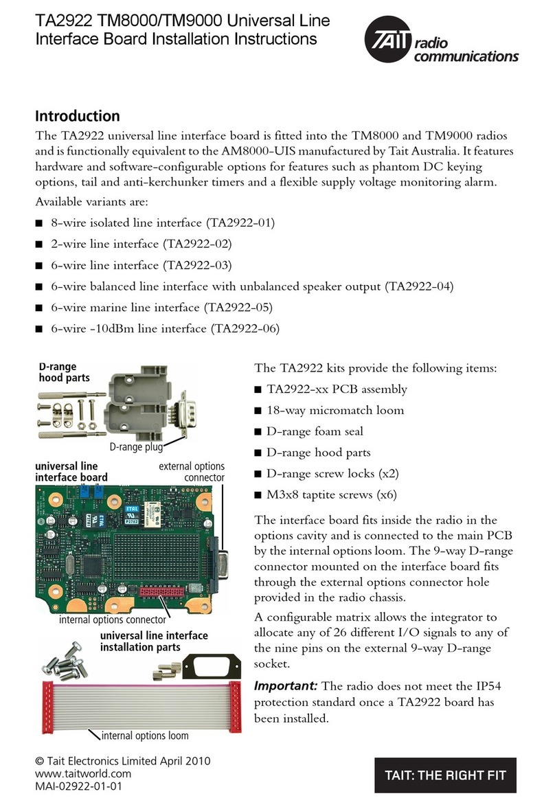
The TA2922 TM8/TM9 universal line interface board is fitted
into the TM8000 and TM9000 radios, and is functionally
equivalent to the AM8000-UIS manufactured by Tait
Australia. It features hardware and software-configurable
options for:
■8-wire line interface
■2-wire line interface with phantom DC keying options,
■4-wire line interface with phantom DC keying options, and
■6-wire E&M interface.
The field programmable microcontroller allows linking/
repeating options to be configured by software, including tail
and anti-kerchunker timers and a flexible supply voltage
monitoring alarm.
A configuratble matrix allows the integrator to allocate any of
26 different I/O signals to any of the nine pins on the external
9-way D-range socket.
The interface board fits inside the radio in the options cavity
and is connected to the main PCB by the internal options
loom. The 9-way D-range connector mounted on the
interface board fits through the external options connector
hole provided in the radio chassis.
1.1 Operation
The TA2922 universal line interface board provides an interface between balanced
600 ohm lines and the TM8000 and TM9000 series radios.
Unbalanced audio allows direct interfacing to equipment using unbalanced audio
(audio referenced to ground) where the input and output levels need to be
adjustable.
Using an appropriate cable, two TA2922 interfaces can be installed into two
TM8000 and/or TM9000 radios for linking purposes. This includes linking of
repeaters (same RF band or mixed RF band) and mobile linking applications, for
example an in-vehicle repeater that communicates between a wide area VHF radio
network and a UHF portable radio.
Important The radio does not meet the IP54
protection standard once an
interface board has been installed
unless the external options cover
seal is installed.
external options
connector
internal options
connector
D
-range
hood parts
D-range plug
universal line
interface board
universal line interface
installation parts
internal options
loom

8TA2922 Universal Line Interface Service Manual
© Tait Electronics Limited March 2010
Data equipment such as a GPS receiver or Computer Controlled Data Interface
(CCDI) is able to be connected to the TA2922 at the same time as the audio
interface is used.
The built in low voltage monitor alarm can be used to send a status message or
Selcall to advise a remote monitoring station of a potential power supply issue.
The TA2922 can be used together with conventional, MPT1327 trunked or P25
radio modes of operation.
1.2 Specifications
Power supply input voltage 10.8 - 16.0VDC, negative ground
Power supply input current 30mA nominal
Over current protection 300mA self-resettable poly-switch fuse
Line out level -30dBm to +10 dBm
Line out impedance 600 ohms
Line in level -30dBm to +5dBm
Line in impedance 600 ohms
PTT in Opto coupled, non polarised, 10 to 50V input range
Gate out Voltage free (normally open) relay contacts. Relay contacts
rated 1A @ 50V DC
PTT in direct Active Low (pull to Ground)
Gate out direct Active low, open collector, 70mA max
EXT_GPIO3 to 7 Five bi-directional digital I/O lines, active low
Input range 0 to 3.3V (3.6V max)
Output range 0 to 3.3V @ 2mA

TA2922 Universal Line Interface Service Manual 9
© Tait Electronics Limited March 2010
1.3 Connections
The following tables summarize the signals used for the universal line interface
board on the internal options connector (SK2) and the external options connector
(SK1).
The signals on SK1 are dependant on the configuration of the matrix. Refer to
“SK1 I/O signal configuration” on page 26.
Internal options connector (SK2)
Pin Radio Signal Signal Description
1 13V8_SW
+13V8_SW switched 13V8 supply from the radio
2 AUD_TAP_OUT AUDIO_TAP_OUT
Programmable tap point out of the receive or
transmit audio chain.
3AGND AGND
analogue ground
4 AUX_MIC_AUD AUX_MIC_AUD
Electret auxiliary external mic
5 RX_BEEP_IN RX_BEEP_IN
beep audio to radio (not implemented)
6 AUD_TAP_IN AUD_TAP_IN
Programmable tap point into the receive or
transmit audio chain
7 RX_AUD RX_AUD
volume controlled Rx audio
8 RSSI RSSI analogue receive signal strength indicator
9 IOP_GPIO1 GPIO1 Radio PTT
IOP_GPIO1 to/from the radio
3V3 logic level, 5V tolerant
10 IOP_GPIO2 GPIO2 Radio Busy
IOP_GPIO2 to/from the radio
3V3 logic level, 5V tolerant
11 IOP_GPIO3 GPIO3
IOP_GPIO3 to/from the radio
3V3 logic level, 5V tolerant
12 IOP_GPIO4 GPIO4 Disable Line
Interface
IOP_GPIO4 to/from the radio
3V3 logic level, 5V tolerant
13 IOP_GPIO5 GPIO5
IOP_GPIO5 to/from the radio
3V3 logic level, 5V tolerant
14 IOP_GPIO6 GPIO6
IOP_GPIO6 to/from the radio
3V3 logic level, 5V tolerant
15 IOP_GPIO7 GPIO7
IOP_GPIO7 to/from the radio
3V3 logic level, 5V tolerant
16
DGND
—
analogue ground
17
IOP_RXD
IOP_RXD
asynchronous serial port - receive data
18
IOP_TXD
IOP_TXD
asynchronous serial port - transmit data
B
D
F
H
J
1!
1#
1%
1&
C
E
G
I
1)
1@
1$
1^
1*
top view

10 TA2922 Universal Line Interface Service Manual
© Tait Electronics Limited March 2010
External options connector (SK1) - TA2922-01 8-wire isolated line interface
External options connector (SK1) - TA2922-02 2-wire line interface
External options connector (SK1) - TA2922-03 6-wire line interface
Pin Signal Description
1 Line out 1 balanced Rx audio output -10dBm into 600 ohms
2 Gate out 1
Rx gate relay contact 1
3GND
DC ground
4 PTT in + DC into Tx key opto coupler (10 to 50V)
5 Line in 1 balanced Tx audio input, 600 ohm impedance, -10dBm
6 Line in 2 balanced Tx audio input, 600 ohm impedance, -10dBm
7 PTT in - DC into Tx key opto coupler (10 to 50V)
8 Gate out 2 Rx gate relay contact 2
9 Line out 2 balanced Rx audio output -10dBm into 600 ohms
hj
b
gi
cdef
outside view
Pin Signal Description
1 Line audio 1 balanced Tx and Rx audio, 600 ohm impedance -
10dBm for 2kHz deviation (wide band)
2 Line audio 2
balanced Tx and Rx audio, 600 ohm impedance -10dBm
for 2kHz deviation (wide band)
3—
4—
5 GND DC ground
6—
7—
8 RAD_DATA_IN RS-232 data from PC for programming
9 RAD_DATA_OUT RS-232 data to PC for programming
hj
b
gi
cdef
outside view
Pin Signal Description
1 Line out 1 balanced Rx audio output -2dBm into 600 ohms for 2kHz
deviation (wide band)
2GND
DC ground
3GND
DC ground
4 +13.8V-SW Switched 13.8V output (unregulated) @ 150mA
5 Line in 1 balanced Tx audio input, 600 ohm impedance, -14dBm
for 2kHz deviation (wide band)
6 Line in 2 balanced Tx audio input, 600 ohm impedance, -14dBm
for 2kHz deviation (wide band)
7 Tx Key PTT in (active low)
8 Rx Gate Rx gate output (connect to gnd via relay contacts when
active)
9 Line out 2 balanced Rx audio output -2dBm into 600 ohms for 2kHz
deviation (wide band)
hj
b
gi
cdef
outside view

TA2922 Universal Line Interface Service Manual 11
© Tait Electronics Limited March 2010
External options connector (SK1) - TA2922-04 balanced line input with
unbalanced speaker output
External options connector (SK1) - TA2922-05 6-wire line interface (marine)
Pin Signal Description
1 Speaker out unbalanced volume controlled audio output 0 to
4.5Vrms into 50 ohms
2GND
DC ground
3GND
DC ground
4 +13.8V-SW Switched 13.8V output (unregulated) @ 150mA
5 Line in 1 balanced Tx audio input, 600 ohm impedance, -14dBm
for 2kHz deviation (wide band)
6 Line in 2 balanced Tx audio input, 600 ohm impedance, -14dBm
for 2kHz deviation (wide band)
7 Tx Key PTT in (active low)
8 Rx Gate Rx gate output (connect to ground via relay contacts
when active)
9GND
DC ground
hj
b
gi
cdef
outside view
Pin Signal Description
1 Line out 1 balanced Rx audio output 0dBm into 600 ohms
2GND
DC ground
3GND
DC ground
4 +13.8V-SW +13.8V-SW Switched 13.8V output (unregulated) @
150mA
5 Line in 1 balanced Tx audio input, 600 ohm impedance, 0dBm
6 Line in 2 balanced Tx audio input, 600 ohm impedance, 0dBm
7 Tx Key PTT in (active low)
8 Rx Gate Rx Gate Rx gate output (connect to ground via relay
contacts when active)
9Lineout2 balanced Rx audio output -2.5dBm into 600 ohms
hj
b
gi
cdef
outside view

12 TA2922 Universal Line Interface Service Manual
© Tait Electronics Limited March 2010
External options connector (SK1) - TA2922-06 6-wire -10dBm line interface
1.4 Compliance
This product complies with the following standards:
■EMC conducted and radiated emissions, CISPR22 for Australia/NZ
■RoHS.
Pin Signal Description
1 Line out 1 balanced Rx audio output -10dBm into 600 ohms
2GND
DC ground
3GND
DC ground
4 +13.8V-SW Switched 13.8V output (unregulated) @ 150mA
5 Line in 1 balanced Tx audio input, 600 ohm impedance, -10dBm
6 Line in 2 balanced Tx audio input, 600 ohm impedance, -10dBm
7 Tx Key PTT in (active low)
8 Rx Gate Rx gate output (connect to ground via relay contacts when
active)
9 Line out 2 balanced Rx audio output -10dBm into 600 ohms
hj
b
gi
cdef
outside view

TA2922 Universal Line Interface Service Manual 13
© Tait Electronics Limited March 2010
2 Circuit description
The TA2922 Universal Line Interface is the TEL production copy of the AM8000-
UIS board designed and manufactured by Tait Australia.
The Universal Line Interface is a TM8000/TM9000 internal options board which
occupies the internal options space within the TM series radio. It performs a range
of flexible audio and digital interfacing between the radio and outside world via a
9-way D-range socket.
The function of each pin in the D-range socket can be user-selected to any of the
board’s available analogue or digital I/O lines by way of a solder shorting link in an
I/O matrix. A number of pre-existing variants of the TA2922 are available with
pre-populated pin functions and pre-calibrated line levels. Refer to “Connections”
on page 9 for pin descriptions on the available variants.
Key functions of the board are:
■each external connector pin function can be user-defined in hardware links
■isolated 2-wire or 4-wire balanced 600 ohm audio interface
SK2
internal options
connector
TA2922-xx line interface board
13V8 switched
AUX-MIC
RSSI
AUD_TAP_OUT
RX_BEEP_IN
RX_AUD
AUD_TAP_IN
TX and RX data
GPIO lines (x7)
1
4
8
2
5
7
6
17-18
9-15
3.3V regulator
3.3V
line out audio
audio source
VR1
W
600
transformer
level monitor
source select
VR2
W
600
transformer
VR3
18F45K20
micro
controller
output
shift
register
status
LED
supply voltage
monitor
profile select
link (LK9)
crystal
oscillator
factory
programming
connector (S2)
SK1
external options
connector
isolated Gate
and TX Key
option links
TX Key input
optocoupler
Gate output relay
low pass
filter
alarm beep
generator
audio
level
detector
RS-232 level
translator
technician
programming
connector (S1)
open collector
RX Gate O/P
un-isolated TX-Key I/P
GPIO lines (x5)
TX and RX data + flow control
balanced
line in
balanced
line out
un-balanced line out
line in
level
adjust
side tone
talk-through
level adjust
(optional)
un-balanced
line in
mute
line out
level adjust
I/O
matrix
26 x 9
polyswitch fuse 9-way
D-Range
socket
SPI data

14 TA2922 Universal Line Interface Service Manual
© Tait Electronics Limited March 2010
■isolated E&M interface with a flexible range of configurations
■unbalanced audio input and output
■all audio I/O is adjustable by high precision 12-turn potentiometers which are
accessible by opening the radio lid
■open collector gate output
■3.3V TX key input
■analogue RSSI and auxiliary microphone lines from radio available as I/O
options
■optional RX line to TX line adjustable level talk-though for headset side tones
and voice recorder systems
■radio internal serial port available as I/O options
■programmable tail/hang time
■programmable ‘anti-kerchunker’ timer
■programmable supply voltage alarm with beeps superimposed on radio TX
audio
■PC based real time monitoring of input and output conditions
■field upgradable software for future upgrades.
2.1 Audio Interface
The audio interface consists of two sections.
Line out
The line out audio interface features:
■radio RX audio to a balanced 600 ohm transformer isolated output
■radio RX audio to an unbalanced 100 ohm un-isolated output.
The line out audio source is software selectable between the fixed level
AUD_TAP_OUT line or the volume controlled RX_AUX line of the TM8000/
TM9000 radio. The audio mute characteristics and flat/de-emphasised
configuration of AUD_TAP_OUT is defined in the programming of the radio
audio options. RX_AUD is de-emphasised and is controlled in level according to
the control head volume control.
Caution In some TM8000/TM9000 configurations the RX_AUD
line becomes fixed in level and is not controlled with the
radio’s volume control, such as when remote head or
multi head configurations are used. Consult your Tait
dealer for more information.
The audio output level is adjusted by potentiometer VR1. Various TA2922
configurations are available from Tait Electronics with the audio output set to a
pre-defined level.

TA2922 Universal Line Interface Service Manual 15
© Tait Electronics Limited March 2010
The balanced output is isolated by a 1:1 600 ohm line transformer, T1. The
transformer secondary has a centre tap for use with DC keying options.
Unbalanced audio is sourced from one half of the power amplifier’s output which
drives the line transformer. The signal is AC coupled and has an output impedance
of 100 ohms, making it suitable for driving loads such as audio headsets.
Line in
The line in audio interface features:
■balanced 600 ohm line in audio to radio TX audio
■unbalanced 50k ohm impedance audio input to radio TX audio.
The line in audio is always available to the radio transmitter at the AUD_TAP_IN
line of the radio internal option connector. The transmitter is enabled when the
TX Key or PTT input to the TA2922 board is activated. The audio filtering and
flat/pre-emphasis selection is defined in the programming of the radio audio
options.
Balanced line input enters the board through a 1:1 600 ohm line transformer, T2,
which also provides line isolation. If a 2-wire audio interface is configured,
transformer T2 is not used and instead all transmit and receive line audio is via
transformer T1. In this 2-wire configuration, link LK4/R62 is fitted for audio
routing which makes the unbalanced audio input unavailable.
When link LK4/R62 is not fitted, the unbalanced line input is available for ground
referenced audio. Input impedance is 50k ohms and the signal is AC coupled.
2.2 TX Key Input
Both opto-isolated and un-isolated transmitter keying options are available.
The optocoupler input operates between 10 to 50V and is not polarity sensitive. It
can be connected to two input lines on the external connector, or be connected
to the centre tap of transformer T1 for line DC keying (also known as phantom
keying) with the suitable placement of option links. Both positive and negative
keying voltages are supported.
The un-isolated TX key input PTT_DIRECT is 3.3V logic compatible where a
DC voltage of under 2.5V keys the transmitter. A 10k ohm 3.3V pull up resistor is
included on this line. The maximum voltage on this line should not normally
exceed 5V. This line can be driven directly from any open collector or relay contact
output.
2.3 RX Gate Output
Both relay isolated and un-isolated open collector outputs are available for RX
gate/busy detect output.

16 TA2922 Universal Line Interface Service Manual
© Tait Electronics Limited March 2010
The default configuration is for ‘clean’ relay contact outputs in the form of two
isolated lines. A variety of relay contact options are available with the specific
population of option links, including 12V or DC ground permanently on one of
the contacts. The relay contacts outputs can also be configured for DC keying
output to the line for centre tap ‘phantom’ DC keying configuration.
An open collector output available as GATE_OUT_DIRECT can sink a 50mA
load. The voltage on this line must never exceed 45V.
2.4 Digital I/O
Five I/O lines from the radio internal options port, IOP_GPIO3 to IOP_GPIO7
are available as bidirectional inputs or outputs which can be connected to any of
the external D-range connector pins with the appropriate population of the I/O
matrix.
An exception is the use of the GPIO4 line. When this is activated (connected to
ground) on the radio IOP_GPIO4 as an output from the radio, the TA2922 enters
a disabled state where all transmit and receive audio and keying functions are
inhibited.
2.5 Serial Data
In the standard configuration, the microcontroller TX and RX data lines are
available as RS-232 inputs and outputs at internal connector S1 for serial
programming of the TA2922 board configuration and for board software upgrades
if required. The same RS-232 data lines can be routed to pins on the D-range
connector for programming the board without opening the radio lid. These lines
connect directly to a PC serial port for communication with the option board
programming software. See “Programming the TA2922 board with the PGM-
UIS” on page 41.
RTS and CTS hardware flow control lines are also available at RS-232 levels,
however, at the time of release, hardware flow control functionality is not a
supported feature of the option board software.
3.3V TTL logic levels are available as opposed to RS-232 levels. This involves the
removal of U8 and the fitting of components D13, R52, R53, R54, R55, R84
and R85.
The TA2922 may be configured to transparently pass serial data to and from the
radio internal option serial port through to the outside world. In this configuration
the same external TX and RX data lines are used for programming, but a power
up timer allows a short period of time where the programming application may
read or write to the TA2922 shortly after power on.
2.6 Microcontroller
A Microchip PIC 18F45K20 microcontroller, U1, forms the centre of the digital
processing, control and monitoring. The device is responsible for:

TA2922 Universal Line Interface Service Manual 17
© Tait Electronics Limited March 2010
■RX gate output control
■TX key input control
■all timing functions
■audio muting
■alarm state detection
■generation of alarm tones
■TX line audio source selection
■bi-directional I/O line processing
■real time monitoring of digital signal states, RSSI level and audio line level.
Serial input to parallel output shift register U5 is used to expand the digital output
functionality of the microcontroller.
The microcontroller is factory programmed with the option board software and
default configuration settings. The configuration settings are technician
programmable via a serial connection to a PC running the option board
programming software. See “Programming the TA2922 board with the PGM-
UIS” on page 41.

18 TA2922 Universal Line Interface Service Manual
© Tait Electronics Limited March 2010

TA2922 Universal Line Interface Service Manual 19
© Tait Electronics Limited March 2010
3 Installation
Note If using the universal line interface board link options on the top side of
the board, these must be set before the board is installed in the radio as
the top side of the universal line interface board is not accessible once the
board is screwed to the radio lid.
3.1 Parts Required
The following table describes the parts required to install a universal line interface
board in a radio. The parts marked with an asterisk (*) are not shown and are used
to connect to the radio’s external options connector.
3.2 Installation Procedure
1. Disassemble the radio in order to gain access to the options cavity.
For detailed disassembly instructions, refer to the TM8000 Service Manual.
The circled numbers in the following instructions refer to items in the diagram.
2. Remove the top cover and lid bfrom the radio to access the options
cavity.
3. Remove the external options connector bung c, if it is fitted.
4. On the inside of the radio lid place the foam seal dover the external options
connector cavity e.
5. With the top side of the universal line interface board ffacing the radio lid,
guide the external options connector ginto the external options connector
cavity.
Quantity Internal Part Number Description Reference
1 362-01111-00 foam seal d
1 362-01108-02 cover seal 1!
2 347-00011-00 4-40x3/16 screws 1@
2 354-01043-00 screw-lock fasteners h
6 349-02062-00 M3x8 screws j
*1 240-00034-00 D-range plug —
*1 240-06010-29 D-range hood —

20 TA2922 Universal Line Interface Service Manual
© Tait Electronics Limited March 2010
6. Screw the external options connector to the radio lid using the two screw-
lock fasteners h.
Tighten the fasteners to a torque of 0.9N·m (8lbf·in).
Important The external options connector screw-lock fasteners must be
tightened correctly before screwing the universal line interface
board onto the mounting posts i.
7. Screw the universal line interface board to the mounting posts on the radio
lid using six M3x8 self-tapping screws j.
Tighten the M3x8 screws to a torque of 1.9N·m (17lbf·in)
Important For the universal line interface board to be installed correctly in
the radio’s options cavity, the internal options connector loom 1)
must be looped in the way shown in the diagram.
8. Plug the unattached end of internal options connector loom 1) into the
internal options connector on the radio main PCB.
9. Refit the radio lid and top cover to the radio and screw the external options
cover seal 1! over the external options connector, using the two 4-40x3/16
screws 1@.
Other manuals for TM8000 Series
4
This manual suits for next models
1
Table of contents
Other Tait Computer Hardware manuals
Popular Computer Hardware manuals by other brands

Welch Allyn
Welch Allyn Connex CS install guide

Analog Devices
Analog Devices MAX22005 manual

IEI Technology
IEI Technology IMBA-C604EP user manual

VIA Technologies
VIA Technologies SOM-6X50 user manual

National Instruments
National Instruments PCIe-1437 Getting started guide

Alesis
Alesis QUADRAVERB Service manual

Texas Instruments
Texas Instruments TMS320 DSP user guide

ICOP Technology
ICOP Technology VDX-6354D user manual

rtd
rtd ECAN1000HR user manual

Desin Instruments
Desin Instruments HS-7000 Series General instructions

National Instruments
National Instruments PCMCIA-GPIB Getting started

RME Audio
RME Audio AO4S-192 user guide