Taiwan Commate Computer Inc. P4BEA User manual

P4BEA User’s Manual
1
P4BEA
Motherboard
User’s Manual
Product Name: P4BEA
Manual Revision: English, 1.0

P4BEA User’s Manual
2
Trademarks
Intel, Socket 478, Pentium 4, Pentium 4 Celeron, Willamette and Northwood,478-pin
FC-PGA2CPU are trademarks of Intel Corporation
Award is a trademark ofPheonix/Award Software International Inc.
MS-DOS, Windows 95, Windows 98, Windows ME, Windows XP, Windows 2000 and
Windows NT are registered trademarks of Microsoft Corporation
Novell is a trademark of Novell Corporation
Realtek is a trademark ofRealtek Semiconductor Corp.
All other brand and product names are trademarks or registered trademarks of their
respective companies.

P4BEA User’s Manual
3
Table of Contents
CHAPTER 1 INTRODUCTION................................................... 5
1.1 Product Overview..........................................................................................5
1.2 Features ........................................................................................................6
1.3 Specifications .................................................................................................6
1.4 Packing List....................................................................................................9
1.5 MotherBoard Layout....................................................................................10
CHAPTER 2 HARDWARE SETUP.......................................... 11
2.1 Installation Procedure.................................................................................11
2.1.1 Jumper Settings...........................................................................................11
2.1.2 CMOS Operation(JRTC)............................................................................12
2.1.3 Keyboard Voltage Setting...........................................................................13
2.1.4 CPU FSB Frequency Setting.....................................................................14
2.1.5 CPU Voltage Setting...................................................................................14
2.1.6 LAN Enable / Disable Setting (JLAN).......................................................15
2.2 Installation of CPU (For Socket 478 CPU)..............................................16
2.3 Installation of Memory.................................................................................16
2.3.1 Installation of 184-pin DIMM (Dual Inline Memory Module)..................16
2.3.2 Removal of 184-pin DIMM..........................................................................16
2.3.3 Memory Configuration.................................................................................17
2.4 I/O Connections/Panel Connections.........................................................17
2.4.1 ATX Power Connector (20-pin ATXPWR)...............................................18
2.4.2 CPU, Chassis Fan Connector (3-pin CPUFAN, CHASFAN)................19
2.4.3 Infrared Connector ( 5*2-pin JIR ).............................................................20
2.4.4 Wake on LAN Connector (3-pin JWOL)...................................................21
2.4.5 Floppy Disk Drive Connector (34-pin FLOPPY) .....................................22
2.4.6 Primary/Secondary IDE Connector (Two 40-pin IDE)...........................22
2.4.7 Back I/O Panel Introduction.......................................................................23
2.4.8 PS/2 Mouse Port (6-pin Mini-Din MS)......................................................23
2.4.9 PS/2 Keyboard Connector (6-pin Mini-Din KB).......................................23

P4BEA User’s Manual
4
2.4.10 Serial Port (9-pin D-Sub. COM1) ..............................................................23
2.4.11 Parallel Port (25-pin D-Sub. PRINTER)...................................................23
2.4.12 USB Connectors (USB1 & USB2).............................................................24
2.4.13 LAN Connector.............................................................................................24
2.4.14 ACT/LNK LED (Green color)......................................................................24
2.4.15 Speed LED (Orange color).........................................................................24
2.4.16 Line Out Connector.....................................................................................24
2.4.17 Line In Connector........................................................................................24
2.4.18 Microphone In Connector...........................................................................24
2.4.19 Game/MIDI Port...........................................................................................25
2.4.20 CDIN Audio (4-pin Black color Connector)..............................................25
2.4.21 Panel Connection (24-pin JFRNT)............................................................26
CHAPTER 3 APPENDIX....................... 錯誤! 尚未定義書籤。

P4BEA User’s Manual
5
Chapter 1 Introduction
1.1 Product Overview
Thanks for your purchasing the P4BEA motherboard. The new generation, 478-pin
FC-PGA2 motherboard P4BEA supports a full range of the latest generation Intel Pentium
4 processors .The leading edge chipset Intel Brookdale 82C845EMCH and
FW82801DB ICH4is designed for working with Pentium 4(1.4GHz-2.53GHz),Pentium4
Celeron, Willamette and Northwood processor in the 478-pin package based on the
VRM 9.0 Spec. And support 400/533 MHz system Data Bus. Built using the leading edge
technology the Intel Pentium 4 processors provide a significant performance over previous
Pentium III processors.
*** WARNING! P4BEA support AGP 2.0 slot for external
AGP 4X mode Graphics Card only.
Two PC2100 DDR SDRAM sockets allow for up to 2.0GB memory capacity. We have
conducted a motherboard compatibility test with a variety of hardware and software, such
as CPUs, memory, display cards, CD ROMs, Novell, MS Office.... etc.
We have set high standards on our quality control, with absolute confidence; we believe
this product is the wisest choice.
This manual is composed of Twosections. The first section is the introduction of this
motherboard, and the second section explains the proper procedure to setup the
motherboard.
Ordering Codes
P4BEA: ATX Socket 478 Pentium 4 / Celeron Motherboard
with Intel 845Eand ICH4 chipset, 533/400 MHz FSB, VGA, LAN,
Audio, USB 2.0 and AGP Interfaces

P4BEA User’s Manual
6
1.2 Features
•Wake up on LAN.
•Wake on Keyboard.
•Modem Remote Ring On.
•Support NCR SCSI BIOS.
•Support Suspend to RAM.
•Support Ultra DMA 33/66/100.
•Support Hardware Monitor function.
•Realtek ALC201A Audio CODEC on board.
•Intel PRO/100+ Fast Ethernet Interfaceon board
•Support FSB frequency 400/533MHz.
•Allows CPU settings and easy over clocking of frequency.
•Support Advanced Configuration Power Interface (ACPI).
•Support Desktop Management Interface (DMI) through BIOS.
•Low-power sleep modes, and 2Mbits“Plug & Play” Flash ROM.
•RTC Wake up Alarm: Program the date/time to wake up your system.
•Support AGP 2.0 slot for external AGP 4X Fast Write protocol graphics card
upgrade. Note :( AGP 1.5V connector only, No support for 3.3V or Universal AGP
connectors).
•Both the BIOS and hardware levels of the motherboard meet PC '99 compliant.
•USB 2.0 interface with up to 480 Mbps of data transfer rate
1.3 Specifications
CPU:
•Support Socket 478 for Intel FC-PGA2 Pentium4 processor.
•Support Intel FC-PGA2 Pentium 4 Northwood / Willamette CPU at 400/533MHz FSB.
•Support Intel FC-PGA2Celeron CPU at 400 MHz FSB
Chipset:
•Intel FW82C845E(MCH) and FW82801DB (ICH4)

P4BEA User’s Manual
7
DIMM:
•Supports 2.5V PC1600/2100 compliant DDR DRAM in 2 184-pin banks, each bank
consists of 1x184-pin DIMM socket, which can support memory sizes of
64/128/256/512MB/1GB modules.
•Supports 4-banks up to 2.0GB DRAM for unbuffered DDR DRAM module.
IDE:
•Dual channel PCI Enhanced IDE ports support up to 4 ATAPI devices such as HDD,
CD-ROM or DVD-ROM.
•Supports PIO Mode 4 with data transfer rate up to 14 MB/Sec.
•Supports Multiword DMA Mode 0, 1, 2.
•Supports UltraATA 33/66/100.
Expansion Slots:
•Six 32-bit PCI expansion slots (Rev. 2.2)
•One AGP4X expansion slot (Rev. 2.0)
•One CNR (Communication Networking Riser) slot
BIOS :
•Award BIOS v6.00PG with built-in Anti-Virus, DMI, ACPI support, and green function
(Plug-and-Play BIOS)
•Supports CD-ROM/HD/SCSI/Floppy/LS120/ZIP boot up.
•Supports NCR SCSI BIOS.
USB Ports :
•Six Universal Serial Bus (USB) ports Rev.2.0, support up to 480 Mbps of data transfer
rate and up to 127 peripheral devices.
Sound :
•Realtek ALC201A Audio codec
•AC '97 Rev 2.2 compliant

P4BEA User’s Manual
8
•18-bit Stereo Full-Duplex.
•Full Duplex Variable Sample Rates from 7kHz to 48kHz with 1Hz Resolution
•Take advantage of CPU to implement audio synthesis and 3D effects processing
•Stereo Headphone Amplifier
•Three Analog Line-Level Stereo Inputs for LINE-IN, CDIN and AUX
•Two Analog Line-Level Mono Inputs for Speakerphone and PC BEEP
•Inside Phat Stereo 3D sound enhancement technology
•Power Management support
•Meet performance requirements for audio on PC2001 systems
•MC' 97 Chained in allowed for multi-channel application
LAN:
•IEEE 802.3 10BASE-T/100BASE-TX compliant physical layer interface.
•IEEE 802.3u Auto-Negotiation support and IEEE 802.3x Full Duplex Flow Control
standard.
•Digital Adaptive Equalization control.
•Link status-interrupt capability.
•Baseline Wander correction.
•10/100Mbps BASE-T auto-polarity correction.
•Automatic detection of “unplugged mode”
•Reduced power in “unplugged mode” (less than 50mW).
I/O Devices :
•One FDD port supports two 3.5" floppy drives up to 2.88 MB.
•Two high-speed 16C550 UART compatible RS-232 serial ports
•One parallel port with SDP/ECP/ EPP compatibility.
•One PS/2 mouse port
•One PS/2 Keyboard port
•One IrDA/ASKIR compatible Infrared interface port.
ATX Power :
•Supports Modem remote Ring-On function
•Supports software power off function
•Supports RTC Wake-Up

P4BEA User’s Manual
9
•Supports Wake up on LAN
•Supports Keyboard Wake-Up
Operating System :
•Supports Windows 3.x/95/98/ME/2000/XP, Windows NT, MS-DOS V6.22, OS/2, Novell,
Unix, SCO UNIX, etc.
Dimension :
•305 x 210 mm (W x L) at ATX Form Factor
1.4 Packing List
The motherboard package contains the following items:
•One Motherboard
•One 80-pin IDE Ribbon Cable
•One Floppy Ribbon Cable
•One Driver CD
•User's Manual

P4BEA User’s Manual
10
1.5 MotherBoard Layout
JFSB
CDIN
AUX
JIR
JWOL
JLAN
JFRNT USBC USBB
BIOS
JRTC
CPUFAN JKBV
PWRFAN
ICH4
Intel
845E

P4BEA User’s Manual
11
Chapter 2 Hardware Setup
2.1 Installation Procedure
1. Jumper settings
2. Installation of CPU
3. Installation of Memory
4. I/O Connections & Panel Connections
2.1.1 Jumper Settings
Reset the Function of Flash CMOS JRTC
Sets the Keyboard Voltage JKBV
Sets the FSB/Core ratio JFSB
Onboard LAN function JLAN
WARNING:
•Electronic parts are Static sensitive. To prevent damage to the computer and its
parts please take the following measures.
•Work on a surface such as concrete, linoleum or hard wood floor.
•Ground your self with either a properly installed grounding strap or by touching a
major electrical appliance long enough to discharge the static.

P4BEA User’s Manual
12
2.1.2 CMOS Operation(JRTC)
How to Clear the CMOS Setting
1. Turn off the power.
2. Remove ATX power cable from connector J1.
3. Remove Jumper Cap from JRTC (2-3) and put on JRTC (1-2) to remove the CMOS
setting.
4. Remove Jumper Cap from JRTC (1-2) and put on JRTC (2-3).
5. Connect ATX power cable back toATX connector.
6. Turn on the power.
While the system reboots, press <DEL> key to set the BIOS setup.
JRTC
1-2Clear CMOS
2-3Normal (Default)
JRTC
1
2
3

P4BEA User’s Manual
13
2.1.3 Keyboard Voltage Setting
This motherboard supports wake on keyboard function. This feature requires that your
system have an ATX power supply with at least 300mA +5V standby power and set this
jumper to 2 & 3 pin short.
JKBV
1-25V
2-35V Stand by (Default)
123
JKBV

P4BEA User’s Manual
14
2.1.4 CPU FSB Frequency Setting
The JFSB jumper provides FSB frequency settings for the CPU. Auto Detect, 400MHz or
533MHz FSB frequency can be selected with this jumper. The over specification operation
is not recommended. Default setting in the 400MHz FSB Frequency.
JFSB
1-2533 Mhz
2-3400 Mhz(Default)
N/C Auto Detect
2.1.5 CPU Voltage Setting
The motherboard supports CPU VID function. It can automatically detect CPU VID signal
and generates proper CPU core voltage.
1
2
3
JFSB

P4BEA User’s Manual
15
2.1.6 LAN Enable / Disable Setting (JLAN)
.Supports LAN function. You can set the LAN function with JLAN jumper.
JLAN
1-2Disabled
2-3Enabled(Default)
JLAN
1
2
3

P4BEA User’s Manual
16
2.2 Installation of CPU (For Socket 478 CPU)
Before installing CPU, make sure the power is off. Locate the level bar on the mPGA478
ZIF socket. Push level bar away from the socket and pull upward 90 degrees. Insert the
CPU into the socket. Be careful of CPU orientation. Make sure the notch of the CPU
corresponds with the white dot on the ZIF socket (the corner without pin socket). Do not
push in the CPU. Make sure all pins are aligned with the CPU socket on the level bar.
2.3 Installation of Memory
This motherboard has 2x184-pin 64-bit Dual Inline Memory Module (DIMM) sockets
divided into 4 banks. You can install 2.5V Unbuffered PC1600/2100-compliant
Synchronous DRAM (DDR DRAM) memory.
Some DIMM memory has SPD (Serial Presence Detect) 8-pinIConmodule.Itisnot
recommended the SPD (Serial Presence Detect) DIMM blends and non-SPDDIMM.
2.3.1 Installation of 184-pin DIMM (Dual Inline Memory Module)
1. Before inserting the DIMM, make sure the pin1 of the DIMM matches with the pin1 on
the DIMM socket.
2. Insert DIMM into the DIMM sockets at a 90-degree angle and press down.
2.3.2 Removal of 184-pin DIMM
1.Press the holding clips on both sides of the socket outward to release the DIMM.
2.Gently pull the DIMM out of the socket.

P4BEA User’s Manual
17
2.3.3 Memory Configuration
There is no jumper setting required for the memory size or type. It is automatically
detected by the system BIOS, and the total memory size is to add them together
2.4 I/O Connections/Panel Connections
I/O Connections
ATXPWR ATX Power series Connector
ATXR1 ATX Power +12V Connector
CPUFAN CPU Fan connector
CHASFAN Chassis Fan connector
JIR Infrared Connector
JWOL Wake up on LAN connector
FLOPPY Floppy Disk Drive Connector
IDE1, 2 Primary/ Secondary IDE Connectors
MS PS/2 Mouse Port
KB PS/2 Keyboard Connector
COM1/JCOM2 Serial Ports 1 & 2
PRINTER Printer Port
USB USB Connector
LAN LAN Connector
GAME Game/MIDI Connectors
LINE_OUT Line out Connector
LINE_IN Line in Connector
MIC Microphone in Connector
CDIN The Connector is for CDIN audio cable
AUX The Connector is for AUX audio cable
DIMM Socket DIMM Modules
DIMM1 PC1600/2100 DDR DRAM 64, 128, 256, 512MB,1GB
DIMM2 PC1600/2100 DDR DRAM 64, 128, 256, 512MB,1GB

P4BEA User’s Manual
18
2.4.1 ATX Power Connector (20-pin ATXPWR)
Make sure that the power supply is off before connecting or disconnecting the power
cable.
PIN assignment
13.3V 11 3.3V
23.3V 12 -12V
3GND 13 GND
45V 14 PS_ON
5GND 15 GND
65V 16 GND
7GND 17 GND
8PW_OK 18 -5V
95V_SB 19 5V
10 12V 20 5V
20 11
10 1
This connector (ATXR1) supplies theCPUoperation voltage (Vcore), besureto
insert below power connector in your motherboard.
Pin assignment
1
GND
2
GND
3
+12V
4
+12V
1 2

P4BEA User’s Manual
19
2.4.2 CPU, Chassis Fan Connector (3-pin CPUFAN, CHASFAN)
Connect the fan's plug to the board taking into consideration the polarity of the connector.
Pin assignment
1GND
2+12V
3FAN_CTL
CPUFAN/CHASFAN
3 2 1

P4BEA User’s Manual
20
2.4.3 Infrared Connector ( 5*2-pin JIR )
This connector supports the optional wireless transmitting and receiving infrared module,
with this module and application software such as Laplink or Win95 Direct Cable
Connection, user can transfer files to or from their laptops, notebooks, PDA, PCs and
printers. The connector supports IrDA (115.2Kbps, 2 meters) and ASK-IR (56Kbps). An
optional consumer infrared (CIR) set connects to the CIR and SIR connectors
simultaneously for both wireless transmitting and remote control functions through one
external infrared module. Install infrared module onto Infrared connector and configure the
setting through “UART Mode Select” in Integrated Peripherals to select whether UART is
directed for use with COM2 or Infrared.
Pin assignment
1VCC 6N.C
2N.C 7CIRRX
3IRRXD 85VSB
4GND 9N.C
5IRRXD 10
N.C
JIR
1 6
5 10
Table of contents
Other Taiwan Commate Computer Inc. Motherboard manuals

Taiwan Commate Computer Inc.
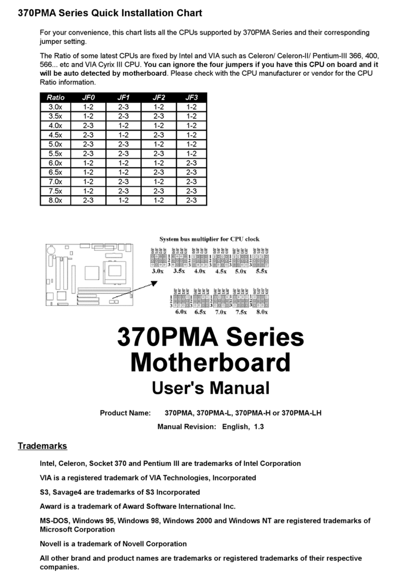
Taiwan Commate Computer Inc. 370PMA Series Original operating instructions

Taiwan Commate Computer Inc.
Taiwan Commate Computer Inc. LV-671Z User manual

Taiwan Commate Computer Inc.
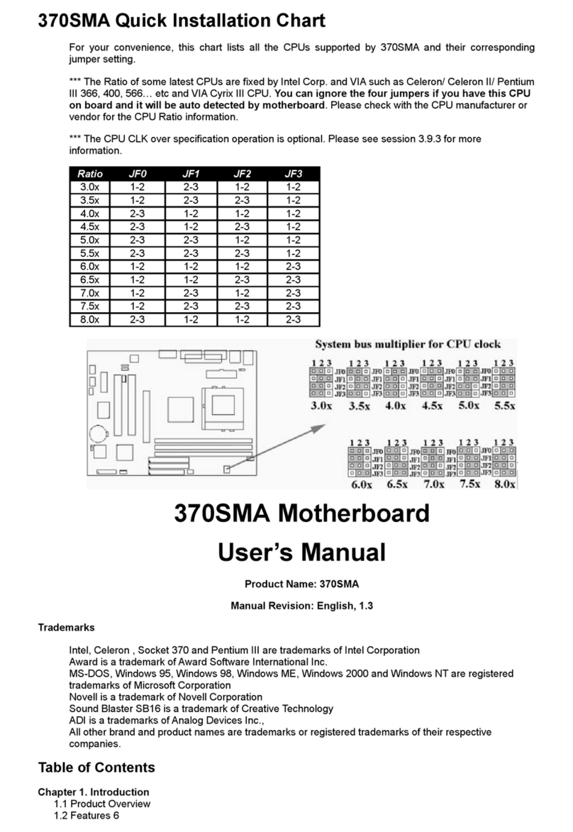
Taiwan Commate Computer Inc. 370SMA User manual

Taiwan Commate Computer Inc.
Taiwan Commate Computer Inc. P4BGA User manual

Taiwan Commate Computer Inc.
Taiwan Commate Computer Inc. PV-DDR User manual