AZZA U601BS User manual

The U601BS Mainboard User Manual Page 1
U601BS Mainboard
User Manual
SOCKET 370 Micro-ATX
Mainboard
Version 1.x
UM-U601BS-E1
Rev 1.0V
Creation Date: 29 November 2001

The U601BS Mainboard User Manual
Page 2
Copyright
This publication contains information that is protected by copyright. No
part of it may be reproduced in any form or by any means or used to
make any transformation adaptation without prior written permission
from the copyright holders. This publication is provided for informational
purposes only. The manufacturer makes no representations or warran-
ties with respect to the contents or use of this manual and specifically
disclaims any express or implied warranties of merchantability or fitness
for any particular purpose. The user will assume the entire risk of the
use or the results of the use of this document. The manufacturer re-
serves the right to revise this publication and make changes to its con-
tents at any time, without prior notice.
2001. All Rights Reserved.
Trademarks
Microsoft®, MS-DOS®, WindowsTM, Windows® 95 and Windows® 98
are registered trademarks of Microsoft Corporation. PentiumTM III, Cop-
permineTM, TualatinTM and CeleronTM are registered trademarks of Intel
corporation. Award is the registered trademark of Award Software, Inc.
Other trademarks and registered trademarks of products appearing in
this publication are the properties of their respective holders.
Package Checklist
This package contains the following items:
•Mainboard
•Users manual
•One IDE cable
•One 34-pin floppy disk drive cable
•One Driver Utility CD
If any of these items are damaged or missing, please contact your
dealer or sales representative for assistance.
Technical Support
If you require additional information or assistance during installation
please contact your dealer. Your dealer will be able to provide the latest
information.
USER’S NOTICE

The U601BS Mainboard User Manual Page 3
Chapter 1:- Introduction
Page 5
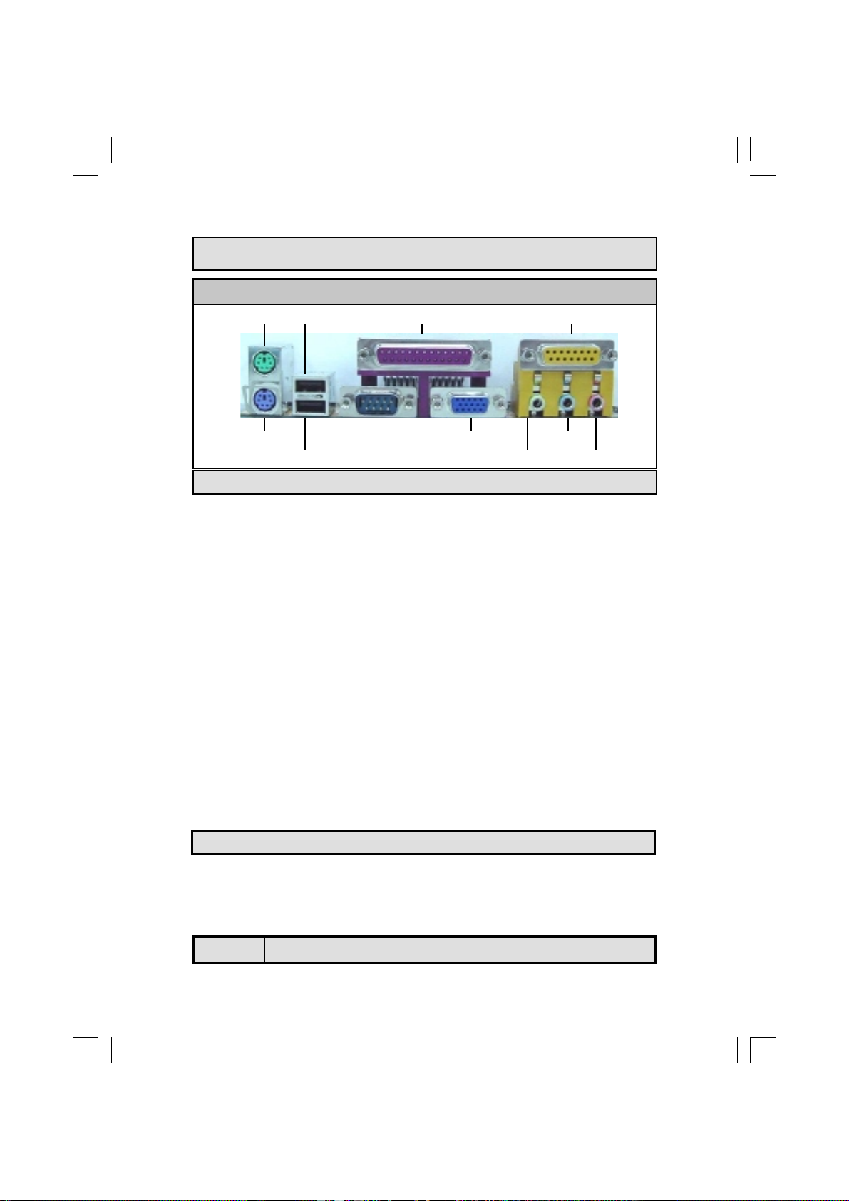
1.1. Mainboard and PC99 ATX External Connector Layout...............................5
1.2. Overview ...................................................................................................6
1.2.1. The U601BS Mainboard ..........................................................................6
1.2.2. Mainboard Dimensions............................................................................6
1.2.3. Environmental Limitations.......................................................................6
1.3. Features and Specifications.......................................................................6
1.4. System Health Monitor Functions..............................................................9
1.4.1. Hardware Monitoring System Utility.........................................................9
1.4.2. Installation.............................................................................................9
1.5. System Intelligence...................................................................................10
Chapter 2:- Hardware Installation
Page 11
2.1. Installation Checklist.................................................................................11
2.2. Installation Steps......................................................................................12
2.3. Expansion Slots, Jumpers and Internal Connectors..................................13
2.4. CPU, Memory and Expansion Slots............................................................14
2.4.1. Installation of the CPU............................................................................14
2.4.2. Memory Modules....................................................................................14
2.4.3. PCI Slots................................................................................................15
2.5. Internal Connectors...................................................................................16
2.5.1. Floppy Disk Drive (FDD) .........................................................................16
2.5.2. Primary and Secondary IDE Connectors...................................................16
2.5.3. CPU and Chassis Fan Connectors.............................................................16
2.5.4. ATX Power Supply Connector..................................................................17
2.5.5. WOL (Wake-On-LAN) Connector .............................................................18
2.5.6. CD Audio In Connector...........................................................................18
2.5.7. USB 3 and USB 4 Connectors..................................................................18
2.5.8. AUX-IN Connector..................................................................................19
2.6. System Panel Buttons and LED Connectors...............................................19
2.6.1. PW: Power On/Off and External Suspend Switch Connector......................20
2.6.2. SL LED Connector ..................................................................................20
2.6.3. IDE HDD LED Connector.........................................................................20
2.6.4. Reset Button Connector..........................................................................20
Table Of Contents

The U601BS Mainboard User Manual
Page 4
2.7. Speaker and Power LED Connectors.........................................................21
2.7.1. Speaker Connector ................................................................................ 21
2.7.2. Front Panel Power LED........................................................................... 21
2.8. External Connectors..................................................................................21
2.8.1. PS/2 Keyboard Connector....................................................................... 21
2.8.2. PS/2 Mouse Connector........................................................................... 21
2.8.3. Serial Port (COM) .................................................................................. 22
2.8.4. Parallel Port Connector (LPT).................................................................. 22
2.8.5. Universal Serial Bus (USB) Port 1 & 2...................................................... 22
2.8.6. Audio/Game Port Connector ................................................................... 22
2.8.7. VGA Port Connecto................................................................................ 23
2.9. Clear CMOS Memory................................................................................23
Chapter 3:- Managing The PC BIOS
Page 24
3.1. AWARD BIOS CMOS Setup Utility ...........................................................24
3.2. Main Menu...............................................................................................24
3.3. Standard CMOS Setup.............................................................................25
3.4. Advanced BIOS Features.........................................................................27
3.5. Advanced Chipset Features.....................................................................31
3.6. Integrated Peripherals............................................................................34
3.7. Power Management Setup......................................................................37
3.8. PNP/PCI Configuration...........................................................................41
3.9. PC Health Status.....................................................................................42
3.10. Frequency/Voltage Control.....................................................................43
3.11. Load Optimized Defaults.........................................................................43
3.12. Set Supervisor Password ........................................................................44
3.13. Set User Password ..................................................................................45
3.14. Save & Exit Setup/Exit Without Saving..................................................46
Appendix A: Optional Items
Page 47
A.1 Standard Infrared Connector..................................................................47
A.2 S/PDIF Connector...................................................................................47
Table Of Contents

The U601BS Mainboard User Manual Page 5
Introduction
Chapter 1
Chapter 1
Chapter 1 -
-
-Introduction
Introduction
Introduction
PC99 ATX External Connector
JP1: Clear CMOS
CN30:
USB3
CN31:
USB4
CN17: CHASSIS FAN
SPKR
PWR-
LED
System Panel
Buttons and
LED Connectors
PCI3
PCI2
PCI1
CN8:
FDC
CN9: IDE1
CN10: IDE2
DIMM2
CN15: ATX
Power Supply
Connector
DIMM1
CPU Socket
CN36: S/PDIF
CN21: CD-IN
CN45: AUX-IN
CN16:
WOL
CN12:
IR
1.1. Mainboard And PC99 ATX External Connector Layout

The U601BS Mainboard User Manual
Page 6
1.2.1. The U601BS Mainboard
The U601BS is a Micro-ATX Socket 370 CPU platform. It based on the VIA
Apollo PLE133T. It is able to support three different FSB Clock speeds: 66
MHz, 100 MHz or 133 MHz. It also supports up to 1GB of SDR SDRAM. It has
four USB ports, three PCI slots. It comes with a number of different connectors
including Auxiliary-In, CD-In and WOL. The infrared (IR) and Sony Phillips
Digital Interface (S/PDIF) connectors are optional items (see appendix A for
further details). It also has a single jumper (for clearing CMOS) and this facili-
tates simplified assembly.
1.2.2. Mainboard Dimensions
Width : 244 mm
Length : 180 mm
1.2.3. Environmental Limitations
Operating Temperature: 10°C to 40°C (50°F to 104°F)
Required Airflow: 50 linear feet/minute across the CPU
Storage Temperature: -40°C to 70°C (-40°F to 158°F)
Humidity: 0 to 90% non-condensing
Altitude: 0 to 10 000 feet
Introduction
1.2. Overview
Processor
Supports Intel® Socket 370 PentiumTM III Coppermine, TualatinTM or Celeron
(0.18μ/0.13μ)
1.3. Features and Specifications
LINE-IN MIC-IN
CN18: MIDI/GAME
CN1: PS/2 KB
CN2: PS/2 MS
CN3: COM CN19: VGA
CN5: LPT
SPK-OUT
CN6: USB1
CN7: USB2
PC 99 ATX External Connector

The U601BS Mainboard User Manual Page 7
Chipset
The U601BS mainboard is based on the VIA Apollo PLE133T:
Northbridge: VT8601T (VT8602)
Southbridge: VT82C686B
CPU Switching Voltage regulator
These mainboards are equipped with a switching voltage regulator that auto-
matically detects a DC power supply from +1.050V to +1.825V.
System Memory
The U601BS mainboard has two 168-pin SDR SDRAM DIMM modules on-
board. These modules are able to support PC-133 and PC-100 SDRAM mod-
ules. A maximum memory of 1GB is supported.
Expansion Slots
The U601BS mainboard is equipped with three dedicated PCI slots
Onboard Audio Features
Supports Microsoft DirectSound/ DirectSound 3D and AC97 Full Duplex.
Word Size
•Data Path: 8-bit, 16-bit, 32-bit, 64-bit
•Address Path: 32-bit
Front Side Bus Frequency (FSB)
FSB frequencies of 66MHz, 100MHz and 133MHz are supported.
BIOS
•Award BIOS, Windows 95/98 Plug and Play (PnP) compatible.
•Supports SCSI sequential boot-up.
•Flash EPROM for easy BIOS upgrades.
•Supports DMI 2.0 function
Desktop Management Interface (DMI)
The mainboard comes with DMI 2.0 built into the BIOS. The DMI utility in the
BIOS will automatically record different information about your system con-
figuration and store this information in the DMI pool, which is a part of the
system board's Plug and Play BIOS. DMI, along with the appropriately net-
worked software, is designed for easy inventory, maintenance and the simpli-
Introduction

The U601BS Mainboard User Manual
Page 8
WOL (Wake-On-LAN) Port
One WOL connector supports Wake-On-LAN functionality.
USB Ports
The U601BS mainboard is equipped with 4 USB ports. USB allows data
exchange between your computer and a wide range of simultaneously
accessible external Plug and Play peripherals. USB 1 and USB 2 are external
ports. They can be found on the PC 99 ATX connector. USB 3 and USB 4 are
internal connectors that can be used to connect other USB devices. (Optional
cable for two connectors is sold separately)
Connectors
•Two IDE connectors.
•One floppy drive interface supports up to two 2.88MB floppy drives.
•One 20-pin ATX power supply connector.
•One CPU Fan connector.
•One Chassis Fan connector
•Two USB connectors
•One WOL connector
•One CD audio-in connector.
•One Auxiliary-in connector.
•One connector for IrDA interface (optional see appendix A)
•One S/PDIF connector (optional see appendix A)
ATX Double Deck Ports (PC 99 color-coded connectors)
•Two USB ports.
•One external DB-9 serial port connector: COM 1.
•One SPP/ECP/EPP DB-25 parallel port.
•One mini-DIN-6 PS/2 mouse port.
•One mini-DIN-6 PS/2 keyboard port.
•One game/MIDI port.
•Three audio jacks: speak-out, line-in and mic-in.
•One VGA port
Introduction
Please note that the internal USB connectors (CN30 and CN31) are
non-standard. When you purchase the cable please ensure that the
connector on one side of the cable is compatible with the internal USB
connector and the connector on the other side of the cable is a stan-
dard USB connector.

The U601BS Mainboard User Manual Page 9
The mainboard is capable of monitoring the following health conditions of your
system:
1. Processor temperature. It has an overheat alarm.
2. VCORE/2.5V/3.3V/5V/12V voltages and failure alarm.
3. Processor and chassis fan speeds. It has a failure alarm for these fans.
4. Read back capability that displays temperature, voltage and fan speed.
Note: Only use this utility in Windows ® 95 or Windows ® 98 operating systems.
1.4.1. Hardware Monitoring System Utility
The mainboard comes with the Hardware Monitoring System utility contained
on the CD. It is capable of monitoring the system’s hardware conditions such
as the temperature of the processor, voltage, and the speed of both the CPU
and chassis fans. You are allowed to manually set a range to the items being
monitored. If the values are over or under the set range a warning message
will automatically pop up. We recommend that you use the Default Settings,
which are the ideal settings that will maintain the system in a good working
condition.
1.4.2. Installation
To install this utility, please insert the CD into the CD-ROM drive. The auto run
screen (Driver Utility) will automatically appear. Click the Hardware Monitoring
button, choose the chipset, model number and the OS that is installed. Please
refer to the CD “Readme” file for further installation instructions.
PCI Bus Master IDE Controller
•Two PCI IDE interfaces support up to four IDE devices.
•Both models support ATA/33, ATA/66 and ATA/100 hard drives.
•PIO Mode 3 and Mode 4 Enhanced IDE (data transfer rate up to
16.6MB/sec.).
•Bus mastering reduces CPU utilization during disk transfer.
•Supports ATAPI CD-ROM, LS-120 and ZIP.
IrDA Interface (Optional)
The mainboard is equipped with an IrDA connector for wireless connectivity
between your computer and peripheral devices. It supports peripheral devices
that meet the HPSIR or ASKIR standard.
1.4. System Health Monitor Functions
Introduction

The U601BS Mainboard User Manual
Page 10
Introduction
Dual Function Power Button
Depending on the setting in the Soft-Off By Power-Button field of the Power
Management Setup, this switch allows the system to enter the Soft-Off or
Suspend mode.
RTC Timer to Power-on the System
The RTC installed on the system board allows your system to automatically
power-on at a set date and time.
Wake-On-LAN Ready
The Wake-On-LAN function allows the network to remotely wake up a Soft
Power Down (Soft-Off) PC. Your LAN card must support the remote wakeup
function. The 5V SB power source of your power supply must be at least
720mA.
ACPI Ready
The mainboard is designed to meet the ACPI (Advanced Configuration and
Power Interface) specification. ACPI has energy saving features that support
OS Direct Power Management (OSPM) for round the clock PC operation.
1.5. System Intelligence

The U601BS Mainboard User Manual Page 11
The following is a checklist of all the expansion slots, jumpers and connectors
that should be configured on your mainboard before you can run your pc.
Hardware Installation
Chapter 2
Chapter 2
Chapter 2 -
-
-Hardware Installation
Hardware Installation
2.1. Installation Checklist
Installation Checklist
Expansion Slots and Sockets
CPU Socket
DIMM Slots
PCI Slots
Socket 370 which supports Intel® PentiumTMIII Celeron or TualatinTM
Two 168 pin slots that supports up to 1GB of SDRAM .
Three 32 bit PCI Slots.
Internal Connectors
CN8
CN9
CN10
CN12
CN13
CN15
CN16
CN17
CN21
CN30
CN31
CN36
CN45
Floppy Disk Drive
Primary IDE
Secondary IDE
Infrared
CPU Fan
ATX Power Supply
Wake On Lan
Chassis Fan
CD Audio In
Universal Serial Bus 3
Universal Serial Bus 4
Sony Phillips Digital Interface
Auxiliary In
FDC
IDE1
IDE2
IR (optional*)
CPU Fan
ATX
WOL
Chassis Fan
CD-In
USB3
USB4
S/PDIF (optional*)
AUX-IN
CN1
CN2
CN3
CN5
CN6
CN7
CN18
CN19
PS/2 Keyboard Connector
PS/2 Mouse Connector
Serial Port 1
Parallel Port
Universal Serial Port 1
Universal Serial Port 2
Game/Audio Port
VGA Port
PS/2 KB
PS/2 MS
COM1
LPT
USB1
USB2
Audio/Game
VGA
External Connectors
*These items are manufacture options. Please see Appendix A for fur-
ther details about these options and how they can be obtained.

The U601BS Mainboard User Manual
Page 12
You need to complete the following installation steps before you can use your PC.
•Check and Set the Mainboard Settings.
•Install the Central Processing Unit (CPU).
•Install the Memory Modules.
•Install the Expansion Cards.
•Connect the Ribbon Cables, Panel Wires and the Power Supply.
•Setup the system BIOS
Before you start installing your mainboard we strongly recommend
that you use a grounded anti-static mat. We further recommend
that you attach an anti-static wristband, which is grounded at the
same location as the mat, to your wrist.
A Diagram of the Expansion Slots, Jumpers and Connectors can be
seen on the following page
2.2. Installation Steps
Hardware Installation
Installation Checklist (Continued)
System Panel Buttons and LED Connectors
PW
SL
HL
RS
Power On/Off and Suspend Switch Connector.
Standby LED Connector
HDD LED Connector
Reset Button Connector
Speaker and Power LED Connector
PWR-LED
SPK Power LED
Speaker Connector
Jumpers
JP1 Clear CMOS

The U601BS Mainboard User Manual Page 13
Hardware Installation
2.3. Expansion Slots, Jumpers and Internal Connectors
CN17: Chassis Fan
1
CN36: S/PDIF
PW SL HLRS
1111
1 PWRLED
1 SPKR
1
1
CN31: USB4
CN30: USB3
CN 10: IDE2
CN 9:
IDE1
JP1: Clear CMOS
1
DIMM 1
DIMM 2
PCI 1PCI 2PCI 3
CN13: CPU Fan
1
1
1
CN 9: IDE1
CN15: ATX Power
Supply Connector
1
CN8: FDC
1
CN21: CD-IN
1
CN45: AUX-IN
1
1
CN16:
WOL
1
CN12:
IR
CN17: Chassis Fan
1
CN36: S/PDIF
PW SL HLRS
1111
1 PWRLED
1 SPKR
1
1
CN31: USB4
CN30: USB3
CN 10: IDE2
CN 9:
IDE1
JP1: Clear CMOS
1
DIMM 1
DIMM 2
PCI 1PCI 2PCI 3
CN13: CPU Fan
1
1
1
CN 9: IDE1
CN15: ATX Power
Supply Connector
1
CN8: FDC
1
CN21: CD-IN
1
CN45: AUX-IN
1
CN21: CD-IN
1
CN45: AUX-IN
1
1
CN16:
WOL
1
CN12:
IR

The U601BS Mainboard User Manual
Page 14
PGA 370
Lock Free PGA 370
Lock Free PGA 370
Lock Free
Alignment Notch
2.4.1. Installation of the CPU
To install your processor, please complete the following set of instructions
1. Locate a small dot marked on the top of the CPU. This mark indicates
Pin 1 of the CPU.
2. Locate Pin 1 (Alignment Notch) the Socket on the mainboard.
3. There is a lever on the side of the socket. First push this lever side-
ways and then lift it to a 90-degree angle.
4. Insert the CPU into the Socket. Please make sure that Pin 1 for the
CPU is inserted into Pin 1 of the Socket.
5. When the CPU is installed correctly push the lever back into place.
6. Install a proper heat sink with cooling fan for proper heat dissi-
pation. Failing to install a heat sink with cooling fan may cause over-
heating which will burnout your CPU and damage your mainboard.
IMPORTANT: CPU COOLING FAN
Please ensure that you have an approved heat sink with cooling fan.
Without a proper heat sink with cooling fan you will damage both the
mainboard and the CPU.
2.4.2. Memory Modules
The U601BS mainboard has two 168-pin DIMM slots and are able to support a
maximum of 1GB PC-100/PC-133 SDR SDRAM. The DIMM slots are located on
the right hand side of the board. To install the DIMM’s into these slots, make
sure the white lever at each side of the slot has been pulled down to an angle
of approximately 45°. Make sure that the DIMM is in the correct orientation.
Place the DIMM on the slot and push down firmly.The white levers will come
back up and lock the module in place (diagram on next page).
Important: The DIMM’s can only be fitted into the slots in one orien-
tation. Make sure that the DIMM’s are in the correct orientation and
the pins are correctly aligned before you insert them.
Hardware Installation
2.4. CPU, Memory and Expansion Slots
CPU Socket 370
Supports
PentiumTM III (0.18μ/0.13μ)
CeleronTM (0.18μ/0.13μ)

The U601BS Mainboard User Manual Page 15
Hardware Installation
168-pin DIMM sockets location
DIMM 1
DIMM 2
10 Pins 31 Pins 43 Pins
PCI Slots
NOTE: “Out Of Memory” Error Message
If you have installed more than 512 MB of RAM and are running Microsoft Windows
Millennium Edition, Windows 98 Second Edition, Windows 98 or Windows 95 you
may experience memory problems. Two symptoms of these problems are being
unable to run an MS-DOS session while you are running Windows or the computer
may stop responding while Windows is starting.
There are three possible solutions to this problem:
1) Reduce the amount of memory Vcache uses to 512 MB or less by altering the
MaxFileCache setting in the System.ini file.
2) Use the System Configuration Utility to reduce the amount of memory Win-
dows uses to 512 MB or less.
3) Reduce the memory installed on your computer to 512 MB or less.
This problem can also occur if you are using an Advanced Graphic Port (AGP)
video adapter.
2.4.3. PCI Slots
The U601BS mainboards comes
with three PCI slots. They are lo-
cated on the left hand side of the
board. Both PCI and PCI expan-
sion cards may require IRQ’s. This
mainboard complies with Plug and
Play (PnP) specifications. When-
ever a PnP compliant card is
added the system will automati-
cally be configured and the IRQ’s
will be assigned automatically.
When you are inserting your PCI
card make sure that the pins are
correctly aligned. When the pins
are properly aligned with the
hole’s in the slot, push down gen-
tly.
49 Pins
PCI3 PCI2 PCI1
11 Pins

The U601BS Mainboard User Manual
Page 16
Hardware Installation
2.5.3. CPU Fan and Chassis Fan Connector
Connector: CN 13 (CPU Fan)/CN 17 (Chassis Fan)
Type: 3 pin
The cooling fans must be connected to their respective power connectors. If
you have installed the hardware-monitoring feature you will be able to monitor
the rotating speed of the CPU cooling fan in your Windows operating system.
Pin 1
2.5.1. Floppy Disk Connector
(FDC)
Connector: CN 8
Type: 34 pin block
The FDD connector can support two
Floppy drives. It is located at the
front of the mainboard. To connect,
use the ribbon-cable that has been
provided. Make sure that the red
strip is connected to PIN 1 of the
connector.
2.5. Internal Connectors
2.5.2. Primary and Secondary IDE connectors
Connector: CN 9 (primary)/ CN 10 (secondary)
Type: 40 pin blocks
The U601BS mainboard has two IDE connectors: a primary and secondary.
Each IDE connector can support two IDE drives. These mainboards can there-
fore support up to four IDE devices each. If you install two hard drives, you
need to configure the second drive to slave mode in the BIOS setup. Please
refer to your hard drive manual for the appropriate jumper settings.
Floppy Disk Connector (FDC)
Primary and Secondary IDE Connectors
IDE2
Pin 1
IDE1
Pin 1

The U601BS Mainboard User Manual Page 17
2.5.4. ATX Power Supply Connector
Connector: CN 15
Type: 20 pin block
This must be connected to an ATX power supply. The plug from the power sup-
ply can only be inserted in one orientation. Make sure the pins are correctly
aligned. Find the correct orientation and push the plug down firmly.
Hardware Installation
ATX Power Supply Connector
Pin 1 Pin 11
+12V
5VSB
PWR_OK
GND
+5VDC
GND
+5VDC
GND
+3.3VDC
+3.3VDC
+5VDC
+5VDC
-5VDC
GND
GND
GND
PS_ON#
GND
-12VDC
+3.3VDC
CPU and Chassis Fan Connectors
1 Ground
2 +12V DC
3 Fan Signal
1 Ground
2 +12V DC
3 Fan Signal
Chassis Fan
CPU Fan

The U601BS Mainboard User Manual
Page 18
2.5.7. USB 3 and USB 4 Connectors
Connector: CN 30 (USB 3)/CN 31 (USB 4)
Type: 5 pin / 5 pin
You already have two USB ports available, USB 1 and 2 (see external connec-
tors). The internal USB connectors allow you to add on an optional kit to ex-
pand the total number of USB ports available. The U601BS has two internal
USB connectors (CN30 and CN31). This enables you to use an extra two USB
devices. Cable for these additional connectors needs to be purchased sepa-
rately.
2.5.6. CD Audio-in Connector
Connector: CN 21
Type: 4 pin un-housed
This mainboard has one CD Audio-in connectors. This connector is used to
connect the CD ROM audio out.
Hardware Installation
2.5.5. WOL Connector
Connector: CN 16 (WOL)
Type: 3 pin
The Wake-On-LAN (WOL) connector
must be connected to a LAN card that
has Wake-On-LAN output. This con-
nector powers up the system when a
wakeup packet or signal is received
through the LAN card.
In order to use the WOL LAN card or the modem to trigger the power on the
PC system, the switching power supply must have the ability to provide a driv-
ing current of at least 720 mA and be connected to a “5V standby” voltage.
WOL Connector
1 5V_SB
2 Ground
3 WOL
CD Audio In Connector
1 Left Channel Audio In
2 Ground
3 Ground
4 Right Channel Audio In

The U601BS Mainboard User Manual Page 19
2.5.8. AUX-IN Connector
Connector: CN 45 (AUX-IN)
Type: 4 pin un-housed
The U601BS mainboard comes with an AUX-IN connector The AUX-IN
connector allows you to receive signals from other audio devices like a radio or
tape.
Note: These are not the standard USB connectors you find on the ATX
PC99 connector. To connect USB devices you need to use an expansion cable
(purchased separately) that ends in a standard USB connector. Ask your re-
tailer for more details.
Hardware Installation
Connectors for USB3 and USB4
1 DC 5V
2 Data-
3 Data+
4 Ground
5 Ground 1 DC 5V
2 Data-
3 Data+
4 Ground
5 Ground
USB3 USB4
Auxiliary-IN Connector
1 Left Channel AUX-IN
2 Ground
3 Ground
4 Right Channel AUX-IN
2.6. System Panel Buttons and LED Connectors
Pin 1 Pin 2
PW Power On/OFF and Suspend Switch
Connector
+5V DC Pull Up Ground
SL Standby LED Connector Standby DC Pull UP Ground
HL HDD LED Connector +5V DC Pull Up Ground
RS Reset Button Connector Reset Control Ground
Buttons and Connectors

The U601BS Mainboard User Manual
Page 20
Hardware Installation
2.6.1 PW: Power On/Off and External Suspend Switch Connector
The Power On/Off connector has two functions. It can be the Power Switch or
Suspend Switch of your PC system. You can either choose “Delay 4 Sec” or
“Instant OFF” (Please refer to the Award BIOS setup instructions in Chapter
3).
Option 1: If you choose “Delay 4 Sec.” In the BIOS CMOS Setup, the func-
tion of “PW” will be:
A. When the system power is "OFF", press this switch, the system will
power on.
B. When system power is "ON”, you can select two different modes: -
Mode 1: Press and hold the Power ON button for less than 4 seconds and then
release it. The system will be turned into Suspend mode (turned into the
GREEN mode) When the system is in the Suspend mode:-
!""Press the Power on button (less than 4 seconds), the system will return
to Full-ON mode.
!""Press and hold the Power On Button for more than 4 seconds, the sys-
tem will be powered off.
Mode 2: Press and hold the Power ON button for more than 4 seconds, the
system will be completely powered off.
Option 2: If you choose “Instant OFF.” In the BIOS CMOS Setup, the power
switch will operate like a normal ON / OFF Power button.
2.6.2. SL LED Connector
When the AC power is “ON” the mainboard will always have a standby voltage
of +5V and the SL LED will be on. If this LED is off it means that the AC power
is “OFF” or has been disconnected.
2.6.3. IDE HDD LED Connector
Any read and write activity by the HDD will turn this LED on.
2.6.4. Reset Button Connector
If you connect this connector, you will be able to reset you computer by press-
ing the reset button at the front of the chassis.
System Panel and LED Connectors
1
PW SL HL RS
111
See table on page 19 for the Pin
assignments and connector
Table of contents
Other AZZA Motherboard manuals

AZZA
AZZA DVAX2+ User manual

AZZA
AZZA 366 Series User manual

AZZA
AZZA P4XE-ANB User manual

AZZA
AZZA PT-6IET User manual

AZZA
AZZA U694 Series User manual

AZZA
AZZA 810T Series User manual

AZZA
AZZA PT-5IVL User manual

AZZA
AZZA 601 Series User manual

AZZA
AZZA P4XA Series User manual

AZZA
AZZA P4 Series User manual