Takstar FE-224N User manual

FE-224N
自动反馈抑制处理器
Automatic Feedback Suppressor
用户手册
User manual
Website: www.takstar.com
地址:广东省惠州市博罗县龙溪镇富康一路2号
全国服务热线:400 6828 333
传真:0752-6383950
邮箱:xs@takstar.com
邮编:516121
网址:www.takstar.com
Guangdong Takstar Electronic Co., Ltd.
Address: No. 2 Fu Kang YiRd., Longxi Boluo
Huizhou, Guangdong 516121 China
Tel: 86 752 6383644
Fax: 86 752 6383952
Email: sales@takstar.com

1
机器重要操作和维护提示
请阅读
保护接地端子
交流电流/电压
危险带电端
表示设备开启
表示设备关闭
警告
警示说明,需注意,
避免可能受伤或死亡的危险。
警告
警示说明,需注意以免造成产品损坏。产品
的报废处理不能混于城市生活垃圾,需单独
收集处理。
警告
机器在接通电源之前,确保主电源电
压与该机器所需电压一致,否则将对机器
造成损坏或可能危害用户安全。机器长时
间不用或打雷闪电时请拔出电源插头,以
避免触电或火灾危险。
外部连接
使用专用电源线连接,以免造成电击/死亡
或火灾危险。若不明白,请联系技术人员
处理。
不要拆除任何外盖
机器内部有高压区,为了避免触电危险,
在电源接通时不要拆除任何外盖。如有必
要,请联系技术人员处理。
内部为非用户维修部件
保险丝
为防止火灾及机器的损坏,确保使用指定
规格保险丝,禁止使用不同规格保险丝。
在换保险丝前,确保关闭机器电源,拔出
电源插头。
保护接地
开启机器前,确保外壳与地连接,避免触电危
险。严禁切断内部或外部的保护接地线或拔出
保护接地端子。
电源线和插头
不要踩踏电源线或插头。
不要断开保护接地连接。
若提供的插头与您的AC座不配套,请联系
技术人员更换电源插座。
电源线与插头不要被重物压到以免有电击或
火灾危险。
操作说明
请根据制造商的指示说明安装机器。
为了避免触电和机器损坏,不要将机器置于
雨水或潮湿环境。切勿在积水旁使用此机器。
不要将机器安装于高温源附近,不要阻塞任
何通风口,以免引起火灾。机器远离明火。
重要安全说明
-阅读安全说明
-遵从安全说明
-注意所有警示内容
-只使用厂商指定配件
清洁
当机器需要清洁时,可用吹风机或干净的布
除去灰尘。
不要使用清洁液,如不纯苯、酒精等。
为了安全,请保持机器干净。
机器的维修
所有维修事项请询求专业技术人员帮助,非
专业人员请不要擅自处理,以免造成触电危
险。
内部高压,小心触电
重要安全指南

每通道有24个独立的可编程滤波器
独立双通道处理
实况使用(Live)与固定设置(Fixed)滤波模式
自动Live滤波
滤波应用选择(Music/Speech)
2输入通道位准计量独立电平显示
每通道24个输入电平指示灯
2*XLR & 2*TRS平衡式输入&输出
后板有按键锁定开关
引言
产品特性
尊敬的用户:
感谢您选购TAKSTAR FE-224N 自动反馈抑制处理器,为了您能够更好的了解使用本产品,
建议您在使用前仔细阅读本说明书。
若存在有疑问或者您有宝贵的建议,可通过拨打得胜官方服务热线
400 6828 333 或使用微信扫描二维码关注得胜官方公众号与我们联系。
重要安全指南...................................................................................................................1
目录................................................................................................................................2
引言................................................................................................................................3
产品特性.........................................................................................................................3
面板功能介绍................................................................................................................4-5
安装与连接...................................................................................................................6-8
用户设置....................................................................................................................9-10
技术规格.......................................................................................................................11
环保说明.......................................................................................................................22
保修卡..........................................................................................................................23
附注.............................................................................................................................25
Important Safety Instruction..........................................................................................................12
Content..............................................................................................................................................2
Preface.............................................................................................................................................13
Features...........................................................................................................................................13
Panel Function............................................................................................................................14-15
Installation and Connection......................................................................................................16-18
User Setup.................................................................................................................................19-20
Specification...................................................................................................................................21
Environment Protection Instruction..............................................................................................22
Warranty Card.................................................................................................................................23
Note.................................................................................................................................................25
目录

(8) AC输入插座与保险丝座
标准IEC电源座,使用提供的电源线连接到AC电源座,在接通电源前,请确保设备的电源要求与
AC提供的电压一致。
若保险丝烧断,应先查明原因并使用相同规格的保险丝更换。
(9) 输入/输出座
对输入连接提供2个类型的输入座:2*XLR母座,2*1/4"TRS座(tip-ring-sleeve)。
处理器能接受的峰值输入电平为+20dBu(参考:0dBu=0.775Vrms)。
(10) 锁定开关
此开关用以锁定/解锁面板的所有按键操作。
后面板
面板功能介绍
FE-224N
前面板
(1) 输入电平指示灯
这4个指示灯用以指示输入电平,范围为-10dBu到+18dBu
注意:在性能较高且操作正确的情况下,平均输入信号应该是0dBu的指示灯一直亮,+10dBu的
指示灯偶尔闪亮。
(2) 削峰指示灯
此指示灯表示输入信号为峰值输入,此时需要适当减小外接的输入信号。
(3) 滤波指示灯
每通道提供24个陷波滤波器(红色指示灯),用以指示激活的陷波滤波器个数,每通道中不停闪烁
的指示灯为正在运行插入的陷波滤波器。
(4) 直通-BYPASS
a) 按钮灯亮,此时信号为直通状态,即内部滤波器未工作。
b) 按钮灯不亮,表示内部滤波器进入工作状态。
关于滤波重设更多相关信息,请查看用户设置部分中的清除滤波器说明。
(5) 清除/设置-CLEAR/SET UP
a) 长按此按钮,直至灯闪烁,用于设置和清除内部固定滤波器。
b) 滤波器红灯闪烁,表示进入滤波器准备状态。
更进一步信息,请参考用户设置部分。
(6) 模式-MODE
a) 点按此按钮进入音乐模式。(按钮灯持续点亮)
b) 再次点按此按钮进入演讲模式。(按钮灯灭)
(7) 电源开关
用以开启/关闭电源。
面板功能介绍

FE-224N
二、接入到调音台的SUB GROUP/MAIN左右插入座
1. 连接TRS(tip-ring-sleeve)立体声座到调音台SUB GROUP/MAIN左右插入座。
2. 连接输出插座立体声座(非平衡式)到本产品通道1的输入,连接返回立体声座(非平衡式)到
本产品通道1的输出。
3. 调整调音台上SUB GROUP/MAIN左右渐变控制钮,以使本产品达到所需的音量。
注意:在性能较高且操作正确的情况下,平均输入信号应该是0dBu的指示灯一直亮,+10dBu的
指示灯偶尔闪亮
安装与连接
FE-224N
一、接入麦克风信通
1. 连接TRS(tip-ring-sleeve)立体声座到调音台麦克风通道插入座。
2. 连接Insert立体声座(非平衡式)到本产品通道1的输入,连接返回立体声座(非平衡式)到本产
品通道1的输出。
3. 调整调音台上麦克风增益控制钮,以使本产品达到所需音量。
4. 使用本产品通道2的连接步骤与通道1一致。
注意:在性能较高且操作正确的情况下平均输入信号应该是0dBu的指示灯一直亮,+10dBu的指
示灯偶尔闪亮
安装与连接

1. 设置音响系统
有3种基本方式可结合您的音响系统来使用本产品,分别为:
1)连接到调音台的麦克风通道:通过“Insert”座(派送/返回)。
2)连接到调音台的SUBGROUP/MAIN输出(左/右),通过“Insert”座(派送/返回)。
本产品到Insert点的连接,可能是较好的选择,大多数调音台上呈现的音量为前置调节,(一般10
dBu),并直接接入本产品,这种方式下任何调节变化都不会修改本产品的设置。
3)连接调音台与PA系统之间的“ON LINE”,从调音台的输出到本产品的输入,从本产品的输出
到PA输入(立体声功放)。以上设置的使用是在insert点不能使用的情况下。
注意:在性能较高且操作正确的情况下,平均输入信号应该是0dBu的指示灯一直亮,+10dBu的指
示灯偶尔闪亮
2. SETUP与LIVE模式
提供每通道24个陷波滤波器(通道1/通道2)及2个主要操作模式:
A-SETUP模式,使用固定滤波器。
B-LIVE模式,SETUP模式未占用的滤波器
SETUP模式用以消除音响系统中由于麦克风摆放原因、不同环境状况等造成的固定频率反馈杂音
问题。这些滤波器被设定后,就不能再被LIVE模式调用,除非复位设置。
LIVE模式用于实时地侦测和消除反馈声,SETUP模式未占用的波滤器,在LIVE模式会自动工作。
1). 使用SETUP模式(确认声音)
固定滤波器是在麦克风使用之前设置,在所有其它音响系统设置完成后进行。
a-首先,调低main mix,关掉所有音乐源,打开麦克风(使用Vocalist或者Sub-group)
b-通过长按CLEAR/SET UP(超过4秒)将本产品调到设置模式。
c-24个滤波器指示灯中的第一个灯开始闪烁,表示通道1或通道2或2通道选择了SETUP模式。
d-用PFL设置每一通道的电平,慢慢调高Main Mixer音量,提高系统的增益,直至出现反馈杂音。
e-本产品通过将陷波滤波器加入合适频率中可检测并消除反馈杂音,继续慢慢调高增益,直至所有
反馈杂音被消除,然后短按CLEAR/SET UP按钮退出设置模式。
所有指示灯亮几秒,表示固定滤波器已被储存并自动选 LIVE模式,余下滤波器使用于LIVE模式中。
若24个滤波器都已使用于SETUP模式,自动设置为SETUP模式,LIVE模式下无滤波器可用。
用户设置
FE-224N
三、连接调音台的输出
1. 使用XLR或TRS(tip-ring-sleeve)立体声座连接调音台的输出(左&右)到本产品的输入(通
道1&通道2)。
2. 连接本产品的输出(通道1&通道2)到功率放大器的输入。
3. 调整调音台上的左-右滑动按钮,以使本产品获得所需的音量。
注意:在性能较高且操作正确的情况下,平均输入信号应该是0dBu的指示灯一直亮,+10dBu的
指示灯偶尔闪亮
安装与连接

模拟输入
2*XLR公座 & 2*1/4" TRS座
输入阻抗
峰值输入电平
模拟输出
2*XLR母座 & 2*1/4" TRS座
输出阻抗
模/数
动态范围
模/数转换
数/模
动态范围
数/模转换
系统性能
取样率
动态范围
总谐波失真
信噪比
频率响应
通道间串音
输入到输出串音
工作电压
消耗功率
尺寸重量
尺寸
净重/毛重
平衡式/非平衡式 ,射频滤波抑制
30k ohm 平衡/15k ohm非平衡
+15 dBu
平衡式/非平衡式 ,射频滤波抑制
100 ohm 平衡/50 ohm非平衡
+15 dBu
114 dB,A-weighted
24 bit
106dB,A-weighted
24 bit
48 kHz
106dB,A-weighted
0.01%,1 KHz
106dB,A-weighted
20Hz to 20 KHz,+/- 0.5 dB
100-240V AC 50/60 Hz
15W
86dB,A-weighted
86dB,A-weighted
483x195x44mm
2.4kg/3.5kg
峰值输入电平
技术规格
10
2). LIVE模式(实时)
本产品通常在LIVE 模式操作(24个陷波滤波器减去固定使用的滤波器)。根据选择的LIVE模式变化
(从MUSIC到SPEECH),一旦检测到新反馈,会自动在此反馈频率上使用LIVE模式滤波器。
若所有LIVE滤波器都有使用后又有新反馈,之前使用的LIVE滤波器会被清除并重新分配到新反馈频
率(相应的指示灯将亮)。
本产品将通过LIVE陷波滤波器持续搜寻反馈频率。
3. 清除滤波器
为了重置/复位LIVE滤波器,按选择通道的CLEAR/SET UP 2秒(按钮蓝色灯闪一下),当前激活的
滤波器将被清除掉且相应指示灯灭。
若希望重设所有滤波器,继续按住CLEAR/SET UP (超过4秒),直到按钮蓝色灯闪亮,说明已进
入SETUP模式且所有FIXED与LIVE滤波器已清除。
4. 锁定开/关
当对本产品完成设置时,可储存这些设置,打开后板上的锁定(LOCK)选择开关。随后,将不能
在前板上进行操作。
5. 自动释放滤波
本产品对每通道提供24个陷波滤波器供用户使用,足够正常性能使用,若要求许多个滤波器,(超
过16个),我们强烈建议对声音系统重新调整。
无论如何,即使本产品使用的是非常窄的陷波滤波器,也尽量避免使用陷波滤波器,以确保整体音
响性能。本产品会实时监控LIVE滤波器的状况,并自动将不需要的滤波器取消以减小对声音系统的
影响。
陷波滤波器Q值
用户设置

24 independent programmable filters for each channel
Independent dual channel processing
Live and fixed filter modes
Automatic live filtering
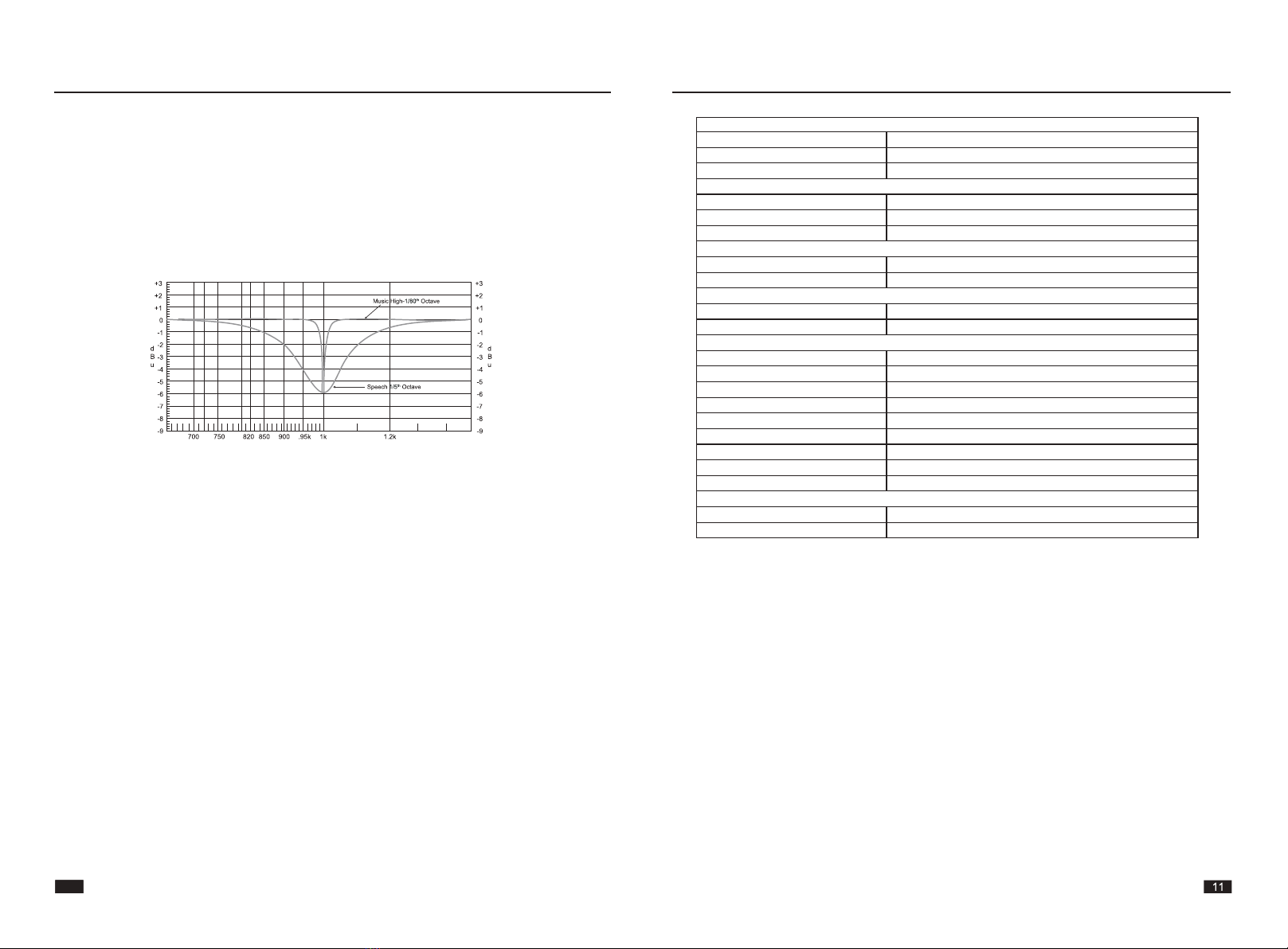
Filter application selection(Music/Speech)
Independent level indication for each input channel
Each channel has 24 input level LEDs
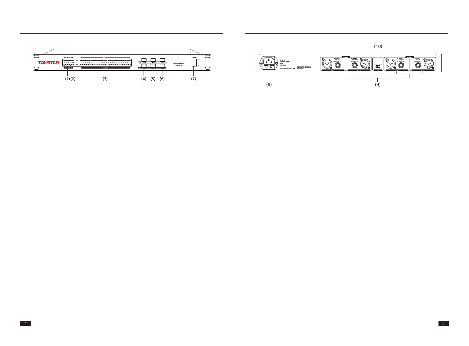
2*XLR & 2*TRS balanced input and output
Button lock switch on the rear panel
Preface
Features
Dear Customer,
Thank you for purchasing TAKSTAR FE-224N Automatic Feedback Suppressor. Please read the
user manual carefully before operation and keep it for reference in future. If you have any
question or suggestion, please contact our local dealer
13
Operation and maintenance instruction
Please read
protection ground terminal
AC current/voltage
risky electric terminal
This means the equipment is turned on.
This means the equipment is turned off.
Caution
Pay attention to the caution instruction.
Prevent from the risk of hurt or death.
Caution
Pay attention to the caution instruction
to avoid product damage. The broken
product has to be collected and
processed separately.
Caution
Before powering on, please make sure
the power supply voltage is right for
the machine, otherwise it leads to
product damage or user hurt. If the
machine will not be used for a long
time or during the thunder and
lightning weather, please disconnect
with the power socket to avoid electric
shock or fire risk.
External connection
Please use the professional power
cord for connection to avoid electric
shock or death or fire risk, and ask
qualified technician to handle the
problem.
Do not disassemble by yourself
High voltage inside! Electric shock risk!
After powering on, do not disassemble
by yourself, and ask qualified technician
to handle the problem.
Do not repair the inner parts by yourself
Fuse
Please use the right type of specific fuse to avoid
product damage or fire risk. It is forbidden to use
the wrong type of fuse. Disconnect with power
supply before replacing the fuse.
Protection ground
Before turning on, please make sure the housing
is connected with the protection ground to avoid
electric shock. It is forbidden to disconnect the
internal or external protection ground cable or
unplug the protection ground terminal.
Power cord and connector
Do not tread on the power cord or connector.
Do not disconnect the protection ground connection.
If the connector does not match with the AC socket,
please ask the qualified technician to replace it.
The power cord or connector can not be put under
the heavy weight to avoid electric shock or fire risk.
Operating instruction
Please connect the machine according to the
instruction of the manufacturer.
Keep the machine away from rain or humid
environment or water to avoid electric shock or
product damage. Keep the machine away from
heat source or fire, and do not block the ventilation
exit to avoid fire risk.
Important safety instruction
-Read the safety instruction.
-Obey the safety instruction.
-Pay attention to all the caution content.
-Only use the parts specified by the manufacturer.
Cleaning
Use hair dryer or dry cloth to clean the dust.
Do not use detergent, e.g. benzol, ethyl alcohol, etc.
Please keep the machine clean for safety.
Maintenance
Only ask the qualified professional technician for
maintenance to avoid electric shock risk.
High voltage inside! Electric shock risk!
Important Safety Instruction
12

(8) AC input socket and fuse holder
The standard IEC power socket. Use the supplied power cord to connect with the power socket.
Before powering on, please make sure the AC voltage is right for the equipment.
If the fuse is broken, check the reason first and then use the same type of fuse to replace.
(9) Input/Output connector
Two types of input connectors: 2*XLR female,2*1/4"TRS (tip-ring-sleeve).
The peak input level of the processor is +20dBu (reference:0dBu=0.775Vrms).
(10) Lock switch
This switch is used to lock/unlock the button operation on the panel.
Rear Panel
Panel Function
15
FE-224N
Front Panel
(1) Input level LED
The four LEDs are used to indicate the input level, ranging from -10dBu to +18dBu.
Note: In the high performance and correct operation status, the average input signal should
be that the LED keeps lighting up at 0dBu and LED flashes occasionally at +10dBu.
(2) Clip LED
This indicates the signal peak input. If the clip LED lights up, decrease the input signal level.
(3) Filter LED
Each channel has 24 notch filters LEDs (red) to indicate the activated notch filter quantity. The
flashing LEDs are the working notch filters.
(4) BYPASS
a) If the button LED lights up, it means the signal is in the bypass status. This means the internal
filters are not working.
b) If the button LED does not light up, it means the signal is not in the bypass status. This means
the internal filters are working.
Refer to the Clearing Filter Instruction in the User Setup Section for more information of clearing
filter.
(5) CLEAR/SET UP
a) Keep pressing this button till the LED flashes. This is used for setting up or clearing the internal
fixed filters.
b) If the red filter LED flashes, it means it enters into the filter ready status.
Refer to User Setting Section for more information.
(6) MODE
a) Press this button to enter into the music mode (button LED keeps lighting up).
b) Press this button again to enter into speech mode (the button LED lights off).
(7) Power Switch
It is used to turn on/off the power supply.
Panel Function
14

FE-224N
2. Connect with SUB GROUP/MAIN L/R input connector of the mixer
(1). Connect TRS(tip-ring-sleeve) stereo connector with SUB GROUP/MAIN L/R input connector
of the mixer.
(2). Connect the stereo output connector (unbalanced) with channel 1 input of this product,
and the return stereo connector (unbalanced) with the channel1 output of this product.
(3). Adjust SUB GROUP/MAIN L/R channel knobs of mixer for the wanted volume of this product.
Note: During high performance and in the correct operation status, the average input signal
should be that the LED keeps lighting up at 0dBu and flashes occasionally at +10dBu.
Installation and Connection
17
FE-224N
1. Connecting with microphone channel
(1). Connect the TRS (tip-ring-sleeve) stereo connector with microphone channel input
connector of the mixer.
(2). Connect Insert stereo connector (unbalanced) with the channel1 input of this product,
and connect the return stereo connector (unbalanced) with channel1 output of this product.
(3). Adjust the microphone gain knob on the mixer for the wanted volume of this product.
(4). Connect channel2 of this product in the same way as that of channel1.
Note: During high performance and in the correct operation status, the average input signal
should be that the LED keeps lighting up at 0dBu and flashes occasionally at +10dBu.
Installation and Connection
16

1. Setup audio system
There are 3 ways to use this product with your audio system:
1)Connect with the microphone channel of the mixer via the Insert connector (send/return).
2)Connect with SUBGROUP/MAIN output (L/R) of the mixer via the Insert connector (send/return).
Connecting the insert connector of this product is a proper selection. Most mixers are designed
with pre-fader adjustment volume(generally 10dBu), and then connect with this product
directly. In this way, any adjustment variation will not change the setting of this product.
3)Connect the ON LINE between mixer and PA system, from the mixer output to the input of this
product, and from the output of this product to PA system input (stereo power amplifier).
When the insert can not be used, the above setting can be used.
Note: During high performance and in the correct operation status, the average input signal
should be that the LED keeps lighting up at 0dBu and flashes occasionally at +10dBu.
2. SETUP and LIVE mode
Each channel has 24 notch filters (CH1 and CH2) and there are two operation modes:
A-SETUP mode: it uses the fixed filters.
B-LIVE mode: it uses the unoccupied filters by SETUP mode.
SETUP mode is used to eliminate the fixed frequency feedback noise of the audio system caused
by microphone positioning or environment. Once these filters are set for SETUP mode, they can
not be used by live mode, only if you reset the setting.
LIVE mode is used to detect and eliminate the feedback noise at real time. The filters unoccupied
by SETUP mode will automatically work.
1). Using SETUP mode (confirm the sound)
Set the fixed filters before using microphone and after finishing setting all other audio system.
a-At first, decrease the main mix level, and turn off all the audio sources, then turn on microphone
(use Vocalist or Sub-group).
b-Keep pressing CLEAR/SET UP (more than 4 seconds) to change to the SETUP mode of the
product.
c-The first one LED of 24 filter LEDs flashes. This means CH1 or CH2 or dual channels select
SETUP mode.
d- Use PFL to set the level of each channel, and increase Main Mix volume slowly, and increase
the system gain till feedback noise appears.
e-This product add notch filters to proper frequency and detect the feedback noise and eliminate
them. Increase the gain slowly till all feedback noise are eliminated, then press CLEAR/SET UP
button to exit the SETUP mode.
User Setup
19
FE-224N
3. Connect with mixer output
(1). Use XLR or TRS (tip-ring-sleeve) stereo connector to connect mixer outputs(left and right)
with the inputs (channel1 & channel2) of this product.
(2). Connect the outputs (channel1 & channel2) of this product with the power amplifier inputs.
(3). Adjust left channel and right channel knobs of the mixer for the wanted volume of this product.
Note: During high performance and in the correct operation status, the average input signal
should be that the LED keeps lighting up at 0dBu and flashes occasionally at +10dBu.
Installation and Connection
18

Analogue Input
2*XLR male & 2*1/4" TRS connector
Input Impedance
Peak Input Level
Analogue Output
2*XLR female & 2*1/4" TRS connector
Output Impedance
A/D
Dynamic Range
A/D Conversion
D/A
Dynamic Range
D/A Conversion
System Performance
Sample Rate
Dynamic Range
THD
S/N Ratio
Frequency Response
Channel Crosstalk
Input to Output Crosstalk
Operating Voltage
Power Consumption
Dimension and Weight
Dimension
Net Weight/Gross Weight
balanced/unbalanced, RF filter suppression
30k ohm balanced/15k ohm unbalanced
+15 dBu
balanced/unbalanced, RF filter suppression
100 ohm balanced/50 ohm unbalanced
+15 dBu
114 dB,A-weighted
24 bit
106dB,A-weighted
24 bit
48 kHz
106dB,A-weighted
0.01%,1 KHz
106dB,A-weighted
20Hz to 20 KHz,+/- 0.5 dB
100-240V AC 50/60 Hz
15W
86dB,A-weighted
86dB,A-weighted
483x195x44mm
2.4kg/3.5kg
Peak Input Level
Specification
21
When all LEDs light up for several seconds, it means the fixed filters are saved and automatically
select LIVE mode, and the rest filters can be used in LIVE mode. If 24 filters are used in SET UP
mode, the LIVE mode has no filter to use.
2). LIVE mode(real time)
Generally, this product is used in LIVE mode (24 filters deduct the fixed filters), and it changes
according to the selected LIVE mode (from MUSIC to SPEECH). Once it detects the new feedback,
it will use the LIVE mode filters for the new feedback frequency. If all LIVE mode filters are
occupied and there is new feedback, the occupied LIVE mode filters will be cleared and
reassigned to the new feedback frequency (the relative LED lights up). This product will detect
the feedback frequency continuously via live notch filters.
3. Clearing filters
To reset the LIVE mode filters, press CLEAR/SET UP button 2 seconds (the blue button LED flashes
once), then the activated filters will be cleared and the relative LEDs light off. If you want to reset
all the filters, press CLEAR/SET UP (more than 4 seconds) till the blue button LED lights up. This
means it enters into SETUP mode and all the FIXED & LIVE filters are cleared.
4. Lock switch
After setting this product, user can use the lock switch on the rear panel to save the setting. After
locking the setting, user can not operate on the front panel.
5. Automatically release the filters
This product has 24 notch filters to use. If you need more than 16 filters to use, we strongly
recommend that you should adjust the audio system again.
Anyway, even if this product uses very narrow notch filters, please use the notch filters as less
as possible to ensure the excellent audio performance. This product monitors the LIVE mode
filter status, and will automatically cancel unwanted filters to reduce affecting audio performance.
notch filter Q
User Setup
20

22 23
环保说明
@
此标志适应于在中国销售的电子信息产品,依据
2006
年
2
月
28
日公布的《电子信息产品污染控制雷理办法》以及
SJ
/T
113
64-
2006
(电子信息产品
污染控制标识要求)
,表示该产品在使用完结后可再利用回数字标识的是怀坦保妒使用期限,只要遵守与本产晶有关和使用的注意事项,从制造
目算起在数字所表示的军限内,产晶不会产生环.t:ft污染和对人体、财产的影响。
电池等附属晶和产品一同包装的,产晶和附属晶的环保使用期限可能不同。
产晶适当使用后报康的方法请遵从点在信息产品的回收、再利用相关法令。详细请咨询各级政府主管部门.
产晶申所含有毒害'相质就元素的各称及含量
部分各称
有毒有害物质就元素
(大体分类}
铅
(Pb)
水银
(Hg)
铜
(Cd)
六价错
(CrV
I)
多澳联苯
(PBB)
多漠二苯腿
(PBDE)
机体{金属部件)
X
。 。 。
。 。
实装基额/电器部件
X 。 。 。
。 。
缆线类
X 。 。 。
。 。
备注
x:
表示该有毒有曹物质在该部件所有均材料申的含量均在
SJ /T
11363-2006
标准规定的限量要求以下
B
Q'
表示该有毒有害物质至少在该部件的某-均质材料申的含量坦出
SJ
111363-2006
标准规定的限量要求。
因为在当代技术下还没有可替代的物质。
参运------------------------------------------------------------------------------------------------------------------~毒
'
E.~
J9i:
1.
本单为保
ff
凭证,请用户
妥善保管,如布遗失,恕
不保修或退换
。
2.
保修期限制:购买之日起
+二个月内。
3.
除了不可抗力事件损环外,
由本公司负责,免费维修。
4.
如属保管不善或使用不当
造成的损坏,维修点将酌
情
收费。
5.
擅自拆卸维修者,不予保
倍。
6.
以上保修条款仅限于中固
市场适用(不包含港澳台
地区)。
严晶服务保证书
姓名:
电话:
地址:
商日口:
型号:
购买日期:
每
月
日
撞催泪'栏{由锺修员填写}
维修员篮鲁
曰翩
·广东得胜电子有限公司
·电话:
4
∞
-6828-333
.地址:广东省惠州市博罗县龙混镇富靡一路
2
号

附注
25
24
-
回国
This manual suits for next models
1
Table of contents
Other Takstar Recording Equipment manuals