Talkaphone ETP-CI-4G-V User manual

ETP-CI-4G-V
Cellular Interface for Verizon
Installation Instructions
Page 1of 5Rev. 12/10/2020
Copyright 2020 Talk-A-Phone, LLC • 7530 North Natchez Avenue • Niles, Illinois 60714 • Phone 773.539.1100 • [email protected] • www.talkaphone.com
All prices and specifications are subject to change without notice. Talk-A-Phone, Talkaphone, Scream Alert, WEBS, and WEBS Contact are registered trademarks of Talk-A-Phone, LLC.
All rights reserved. All other trademarks mentioned in this document or website are the property of their respective owners and does not imply or indicate any approval, endorsement,
sponsorship, or affiliation with such owners unless such approval, endorsement, sponsorship, or affiliation is expressly indicated.
I. Introduction
The ETP-CI-4G-V is used in conjunction with an ETP-500 Series ADA-compliant, hands-free Emergency
Phone.
II. Prerequisite Cellular Service Requirements
Prior to installation and setup, the ETP-CI-4G-V Cellular Interface has the following perquisite requirements:
(1) 4G Voice over LTE service (i.e. voice and data) from Verizon;
(2) An activated 4G micro-SIM (3FF) card provided by Verizon.
III. Contents
Before beginning installation, make sure you have all the included components. The ETP-CI-4G-V includes:
Qty.
Part Number
Description
1
68746
ETP-CI-4G-V Cellular Interface
1
160-00049
MIMO antenna kit (includes antenna with built-in cable
assembly)
2
4247
8-32 x 1/2 BH Screw
2
4248
8-32 x 5/16 Hex Nut
2
42767
#10 External Lock Washer
WARNING: Currently due to the modem chipset and the Verizon certification process, the ETP-CI-4G-V Cellular Interface cannot dial
911. Phone number strings must consist of a ten-digit phone number that includes an area code. Eleven-digit dialing is accepted when
the first digit is a ‘1’.
Support for 911 dialing will be provided as a firmware update and is anticipated for Q4 2020/Q1 2021.
IMPORTANT NOTES:
(1) This model supports programming of the ETP-110/ETP-500 Series Analog Call Stations through a remote call to the ETP-CI-
4G-V Cellular Interface. This remote programming feature is only supported on the 4G LTE Cellular Interface for the Verizon
Network.
(2) The built-in auto-dialer of the ETP-110/ETP-500 Series Analog Call Station cannot dial a secondary number in round robin
fashion when used in conjunction with the ETP-CI-4G-V Cellular Interface.
(3) All programming, diagnostics, and identification of the ETP-110/ETP-500 Series Analog Call Stations are accomplished through
the transmitting and receiving of DTMF signals. Cellular transmissions and cellular networks may interfere with and distort
these tones. As a result of these irregularities, model ETP-TAL Talk-A-Lert Polling and Listening may not function as intended
and, therefore, may not be appropriate in that application or environment.

ETP-CI-4G-V
Cellular Interface for Verizon
Installation Instructions
Page 2of 5Rev. 12/10/2020
Copyright 2020 Talk-A-Phone, LLC • 7530 North Natchez Avenue • Niles, Illinois 60714 • Phone 773.539.1100 • [email protected] • www.talkaphone.com
All prices and specifications are subject to change without notice. Talk-A-Phone, Talkaphone, Scream Alert, WEBS, and WEBS Contact are registered trademarks of Talk-A-Phone, LLC.
All rights reserved. All other trademarks mentioned in this document or website are the property of their respective owners and does not imply or indicate any approval, endorsement,
sponsorship, or affiliation with such owners unless such approval, endorsement, sponsorship, or affiliation is expressly indicated.
IV. Installing the Antenna
The ETP-CI-4G-V Cellular Interface includes a remote-mounting MIMO antenna. The remote-mounting MIMO
antenna should be attached to the Talk-A-Phone enclosure (e.g., ETP-MTE-W, ETP-MT/R-SOLAR, ETP-MT/R-
PCS, etc.) via the built-in antenna mounting hole. To install the remote-mounting MIMO antenna, please follow
the separate antenna mount instructions included with the remote-mounting MIMO antenna.
Figure 1. An example of mounting the remote-mounting MIMO antenna onto the cap of an ETP-MT/R-PCS tower.
The remote-mounting MIMO antenna will be connected to the ETP-CI-4G-V Cellular Interface through the ports
listed in Section V.2.
V. Installing the Cellular Interface
1. The front panel of the ETP-CI-4G-V Cellular Interface provides the following:
(1) Cellular signal strength indicator;
(2) LED indicators for POWER, STATUS, CELL, and GPS;
(3) DATA port reserved for future use;
(4) MODE button reserved for future use;
(5) RESET button for rebooting the cellular interface;
(6) PHONE-FXS port for connecting to an ETP-500 Series Phone.
Figure 2. Front panel of the ETP-CI-4G-V Cellular Interface.

ETP-CI-4G-V
Cellular Interface for Verizon
Installation Instructions
Page 3of 5Rev. 12/10/2020
Copyright 2020 Talk-A-Phone, LLC • 7530 North Natchez Avenue • Niles, Illinois 60714 • Phone 773.539.1100 • [email protected] • www.talkaphone.com
All prices and specifications are subject to change without notice. Talk-A-Phone, Talkaphone, Scream Alert, WEBS, and WEBS Contact are registered trademarks of Talk-A-Phone, LLC.
All rights reserved. All other trademarks mentioned in this document or website are the property of their respective owners and does not imply or indicate any approval, endorsement,
sponsorship, or affiliation with such owners unless such approval, endorsement, sponsorship, or affiliation is expressly indicated.
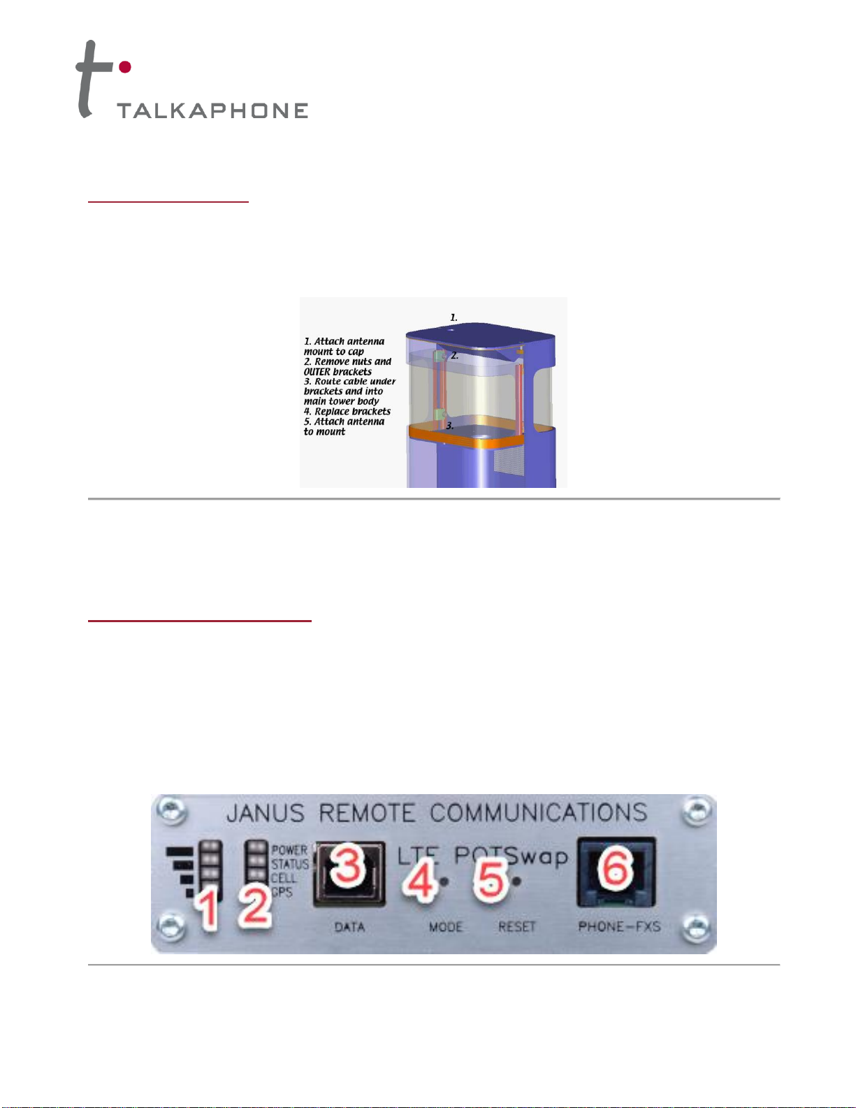
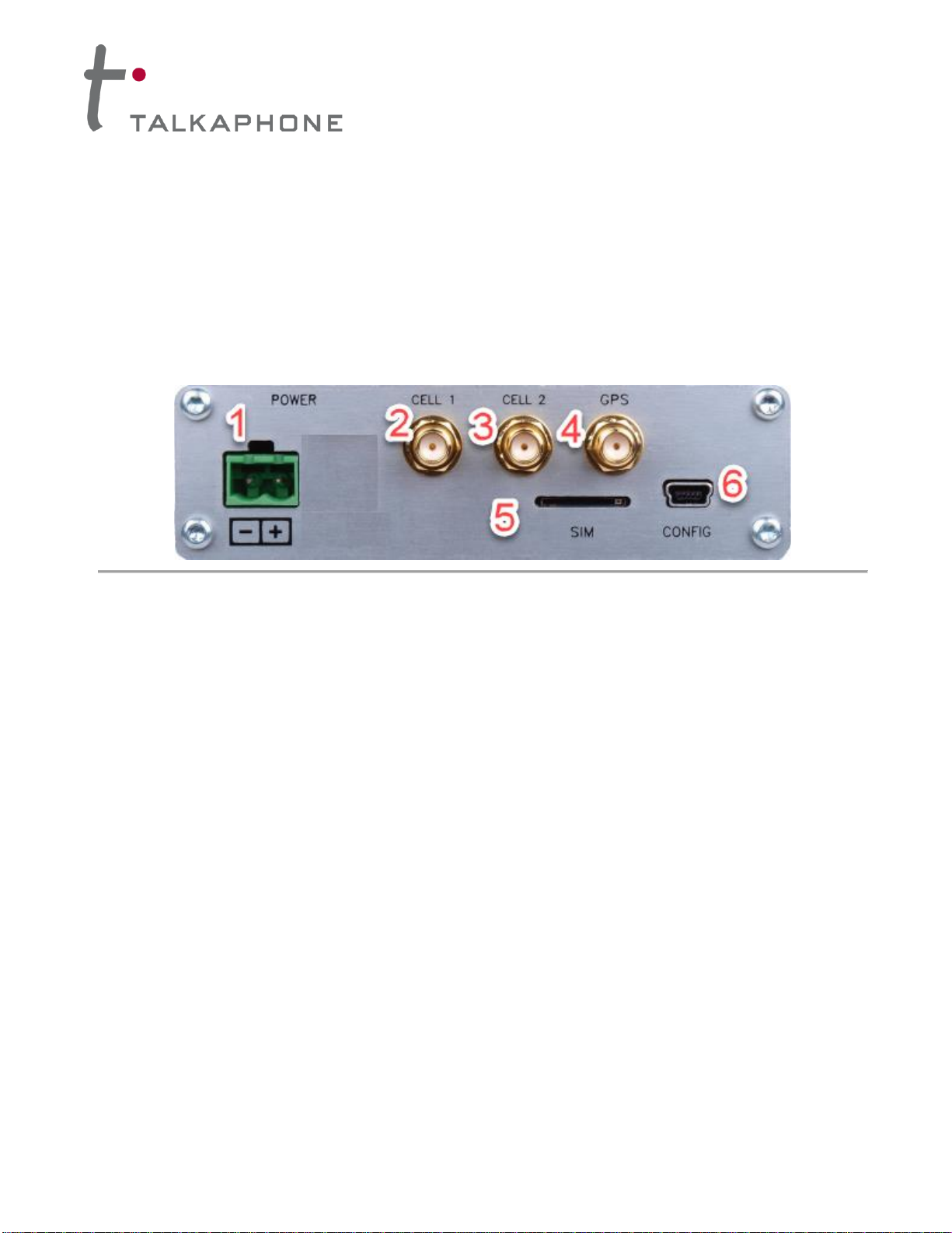
2. The rear panel of the ETP-CI-4G-V Cellular Interface provides the following:
(1) Input terminal for 12VDC;
(2) CELL 1 connector for remote-mounting MIMO antenna;
(3) CELL 2 connector for remote-mounting MIMO antenna;
(4) GPS connector for remote-mounting MIMO antenna;
(5) SIM slot for micro-SIM (3FF) card;
(6) CONFIG port for a mini-USB connection (for Talkaphone Technical Support purposes only).
Figure 3. Rear panel of the ETP-CI-4G-V Cellular Interface.
3. Insert the micro-SIM (3FF) card into the slot labeled SIM (see Figure 3 –Item 5).
IMPORTANT: The orientation of the micro-SIM card should be angled notch entering the slot first with
the metal contacts facing down.
4. Using a plastic spudger or a small flat head screwdriver, push the micro-SIM card into the slot until a
click is heard. To remove the micro-SIM card, push the card until a click is heard and the card springs
out of the slot.
5. Connect the cables from the remote-mounting MIMO antenna to the CELL 1, CELL 2, and, GPS
connecters (see Figure 3 –Items 2, 3, and 4.On the built-in cable assembly of the remote-mounting
MIMO antenna, there are two (2) cables labeled CELL –connect those cables to the CELL 1 and
CELL 2 connectors. Any of the two CELL cables can connect to either connector.
6. Connect the ETP-500 Series Phone to the PHONE-FXS port.
7. If the interface is being powered by an SLR Series (solar) kit, connect the LOAD terminals of the solar
controller to the appropriate polarity markings on the POWER terminal (12VDC input) of the ETP-CI-
4G-V Cellular Interface. Otherwise, connect a 12VDC power source appropriately with respect to
polarity.
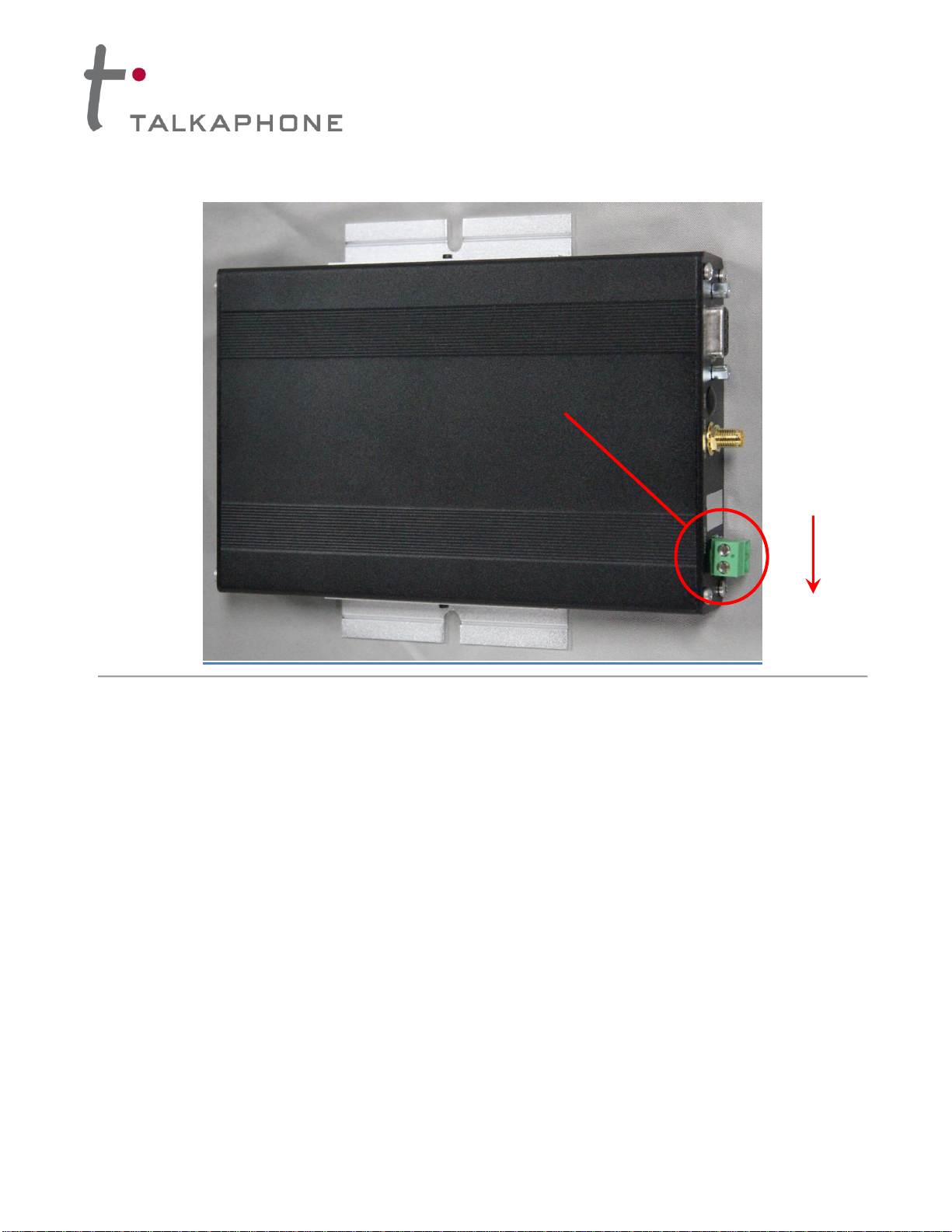
8. Using the built-in mounting flanges, attach the ETP-CI-4G-V Cellular Interface onto the internal
mounting panel of the Talk-A-Phone enclosure (e.g., ETP-MTE-W, ETP-MT/R-SOLAR). The ETP-CI-
4G-V Cellular Interface should be mounted so that the 12VDC input terminal is on the lower right corner
(i.e. toward the Earth).

ETP-CI-4G-V
Cellular Interface for Verizon
Installation Instructions
Page 4of 5Rev. 12/10/2020
Copyright 2020 Talk-A-Phone, LLC • 7530 North Natchez Avenue • Niles, Illinois 60714 • Phone 773.539.1100 • [email protected] • www.talkaphone.com
All prices and specifications are subject to change without notice. Talk-A-Phone, Talkaphone, Scream Alert, WEBS, and WEBS Contact are registered trademarks of Talk-A-Phone, LLC.
All rights reserved. All other trademarks mentioned in this document or website are the property of their respective owners and does not imply or indicate any approval, endorsement,
sponsorship, or affiliation with such owners unless such approval, endorsement, sponsorship, or affiliation is expressly indicated.
Figure 8. This photo illustrates the appropriate orientation and mounting position for the ETP-CI-4G-V Cellular Interface.
Earth
12VDC
Input Terminal

ETP-CI-4G-V
Cellular Interface for Verizon
Installation Instructions
Page 5of 5Rev. 12/10/2020
Copyright 2020 Talk-A-Phone, LLC • 7530 North Natchez Avenue • Niles, Illinois 60714 • Phone 773.539.1100 • [email protected] • www.talkaphone.com
All prices and specifications are subject to change without notice. Talk-A-Phone, Talkaphone, Scream Alert, WEBS, and WEBS Contact are registered trademarks of Talk-A-Phone, LLC.
All rights reserved. All other trademarks mentioned in this document or website are the property of their respective owners and does not imply or indicate any approval, endorsement,
sponsorship, or affiliation with such owners unless such approval, endorsement, sponsorship, or affiliation is expressly indicated.
VI. Activation of Cellular Service
Obtain 4G voice over LTE service (i.e. voice and data) from Verizon. Per the aforementioned installation
instructions, install an activated micro-SIM card provided by Verizon into the ETP-CI-4G-V Cellular Interface.
VII. Programming the ETP-500 Series Phone
The ETP-500 Series Phone requires specific programming for operation with the ETP-CI-4G-V Cellular
Interface. At minimum, the ETP-500 Series Phone should be programmed with the following codes:
* 4 **
* 13 * <Phone_Number_to_Dial> *
* 14 * 1 *
* 18 * 5 *
* 24 * 0 *
* 27 * 0 *
* 55 *
* 56 *
* 58 * <Speak_to_Record_Voice_Message>(optional)
For a full comprehensive list of programming codes, reference the Installation & Operation Manual for
Emergency/Information Phones.
Table of contents
Other Talkaphone Recording Equipment manuals