manuals.online logo
Brands
  1. Home
  2. •
  3. Brands
  4. •
  5. Talkaphone
  6. •
  7. Recording Equipment
  8. •
  9. Talkaphone ETP-GSM User manual

Talkaphone ETP-GSM User manual

ETP-GSM –Cellular Interface
Installation Instructions
Page 1of 10 Rev. 12/16/2014
Copyright 2014 Talk-A-Phone Co. • 7530 North Natchez Avenue • Niles, Illinois 60714 • Phone 773.539.1100 • [email protected] • www.talkaphone.com.
All prices and specifications are subject to change without notice. Talk-A-Phone, Scream Alert, WEBS and WEBS Contact are registered trademarks of Talk-A-Phone Co. All rights reserved.
All other trademarks mentioned in this document or website are the property of their respective owners and does not imply or indicate any approval, endorsement, sponsorship, or affiliation
with such owners unless such approval, endorsement, sponsorship, or affiliation is expressly indicated.
I. Introduction
The ETP-GSM is used in conjunction with an ETP-400 Series ADA-compliant, hands-free Emergency Phone.
II. Prerequisite Cellular Service Requirements
Prior to installation and setup, the ETP-GSM Cellular Interface has the following perquisite requirements:
(1) 3G voice service from a local cellular service provider that supports GSM (e.g. AT&T, T-
Mobile);
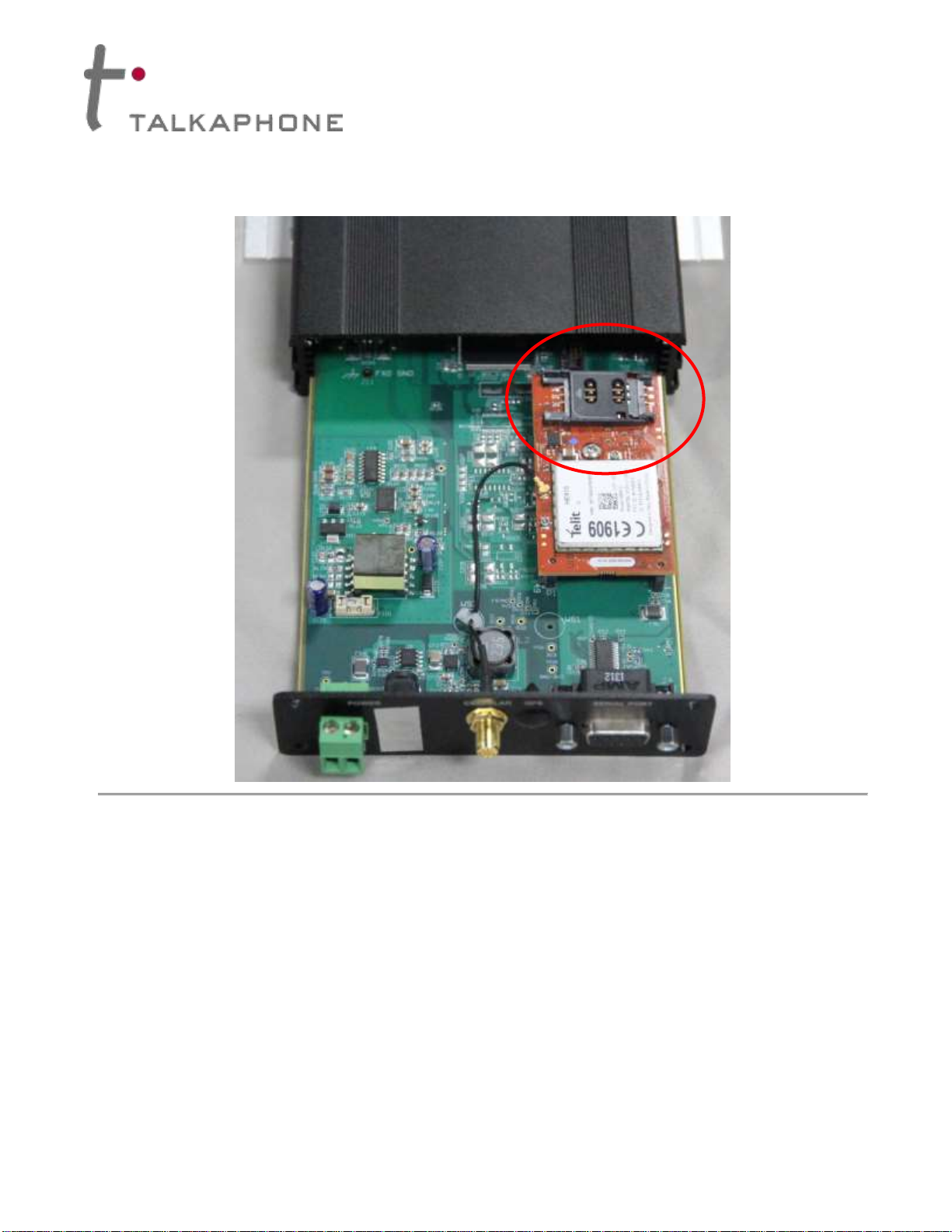
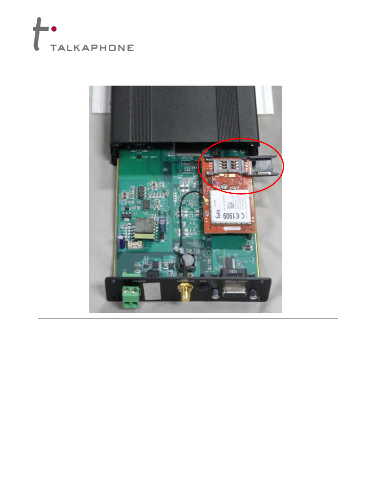
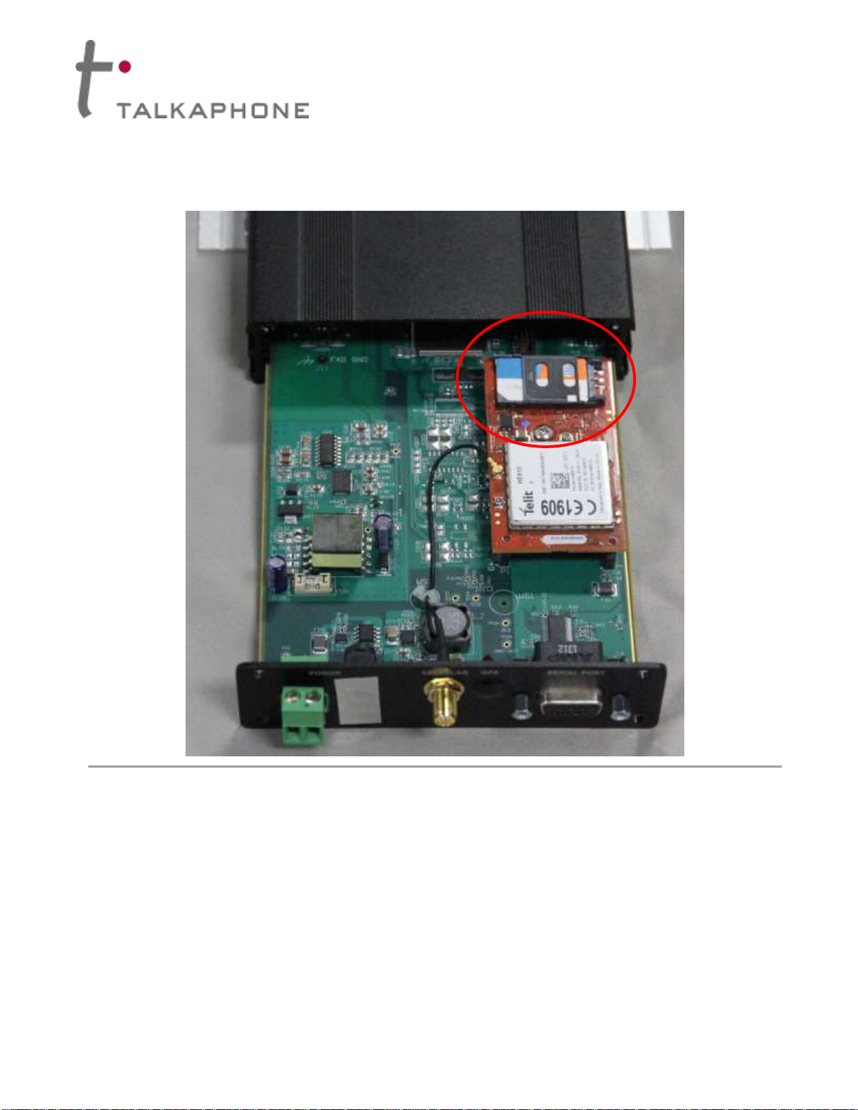
(2) An activated SIM card provided by the local cellular service provider.
III. Contents
Before beginning installation, make sure you have all the included components. The ETP-GSM includes:
Qty.
Part Number
Description
1
68696
GSM Cellular Interface
1
68416GSM
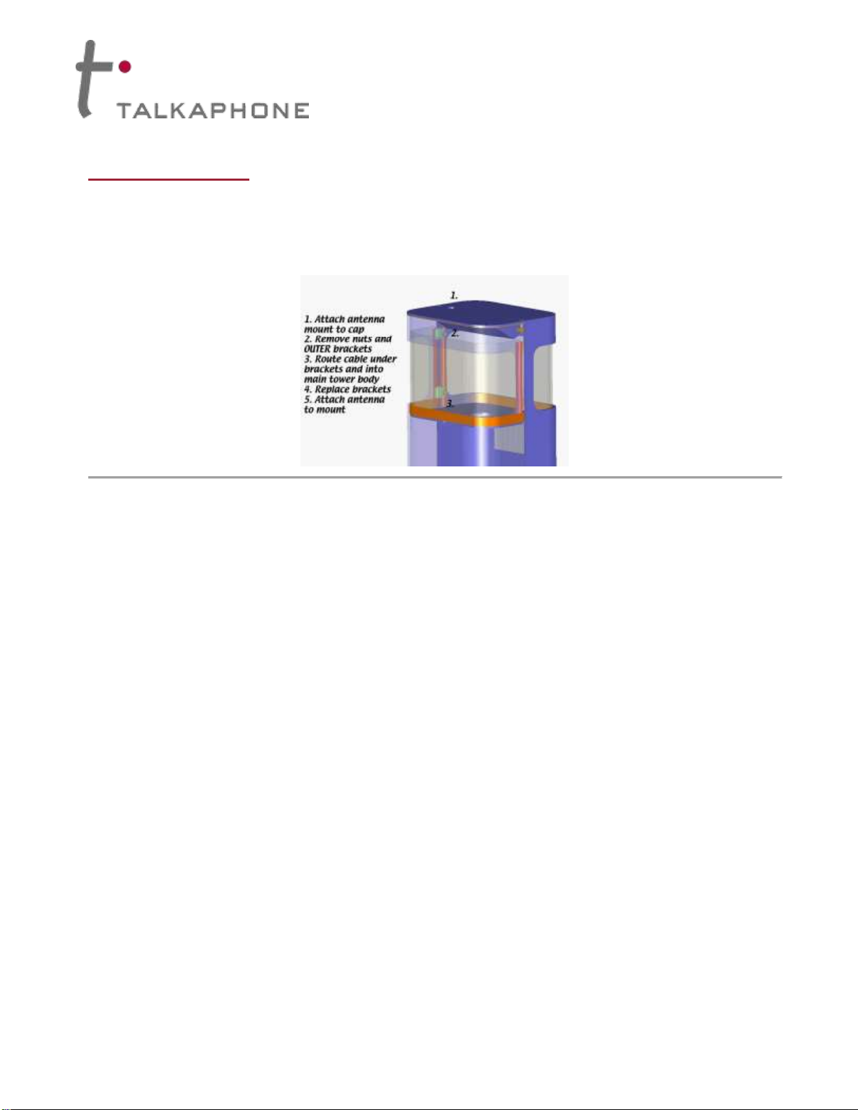
Remote-mounting Omni-directional Antenna
1
19679
Antenna Mount with Cable Assembly
1
42929
Torx T10 L-Key
2
4247
8-32 x 1/2 BH Screw
2
4248
8-32 x 5/16 Hex Nut
2
42767
#10 External Lock Washer
IMPORTANT NOTE: The ETP-GSM Cellular Interface does not comply with Enhanced 911 (E911)
requirements mandated by the Federal Communications Commission (FCC). In order to comply
with the E911 mandate, the ETP-GSM Cellular Interface software prohibits the dialing of 911.
IMPORTANT NOTE: Programming of the ETP-400 Series Phones cannot be done through a
remote call to the ETP-GSM Cellular Interface. For programming, an ETP-400 Series Phone must
be connected directly to a standard analog phone line connection.
IMPORTANT NOTE: The built-in auto-dialer of the ETP-400 Series Phone cannot dial a secondary
number in round robin fashion when used in conjunction with the ETP-GSM Cellular Interface.
IMPORTANT NOTE: All programming, diagnostics, and identification of the ETP-400 Series
Phones are accomplished through the transmitting and receiving of DTMF signals. Cellular
transmissions and cellular networks may interfere with and distort these tones. As a result of these
irregularities, model ETP-TAL Talk-A-Lert Polling may not function as intended and, therefore, may
not be appropriate in that application or environment; ETP-TAL Talk-A-Lert Base Station will not
function at all.
In any event, due to these irregularities, programming of the ETP-400 Series Phone should be done
on a land line (i.e., not through the ETP-GSM Cellular Interface.
ETP-GSM –Cellular Interface
Installation Instructions
Page 2of 10 Rev. 12/16/2014
Copyright 2014 Talk-A-Phone Co. • 7530 North Natchez Avenue • Niles, Illinois 60714 • Phone 773.539.1100 • [email protected] • www.talkaphone.com.
All prices and specifications are subject to change without notice. Talk-A-Phone, Scream Alert, WEBS and WEBS Contact are registered trademarks of Talk-A-Phone Co. All rights reserved.
All other trademarks mentioned in this document or website are the property of their respective owners and does not imply or indicate any approval, endorsement, sponsorship, or affiliation
with such owners unless such approval, endorsement, sponsorship, or affiliation is expressly indicated.
IV. Installing the Antenna
The ETP-GSM Cellular Interface includes a remote-mounting omni-directional antenna. The remote-mounting
antenna should be attached to the Talk-A-Phone enclosure (e.g. ETP-MT/R-OP-SOLAR tower) via the built-in
antenna mounting hole. To install the remote-mounting antenna, please follow the separate antenna mount
instructions included with the remote-mounting omni-directional antenna.
Figure 1. An example of mounting the remote-mounting antenna onto the cap of an ETP-MT/R-OP-PCS tower.
The remote-mounting antenna will be connected to the ETP-GSM Cellular Interface.
ETP-GSM –Cellular Interface
Installation Instructions
Page 3of 10 Rev. 12/16/2014
Copyright 2014 Talk-A-Phone Co. • 7530 North Natchez Avenue • Niles, Illinois 60714 • Phone 773.539.1100 • [email protected] • www.talkaphone.com.
All prices and specifications are subject to change without notice. Talk-A-Phone, Scream Alert, WEBS and WEBS Contact are registered trademarks of Talk-A-Phone Co. All rights reserved.
All other trademarks mentioned in this document or website are the property of their respective owners and does not imply or indicate any approval, endorsement, sponsorship, or affiliation
with such owners unless such approval, endorsement, sponsorship, or affiliation is expressly indicated.
V. Installing the Cellular Interface
1. The front panel of the ETP-GSM Cellular Interface provides the following:
(1) Cellular signal strength indicator;
(2) LED indicators for POWER, CELLULAR, and STATUS;
(3) PHONE-FXS port for connecting to an ETP-400 Series Phone.
Figure 2. Front panel of the ETP-GSM Cellular Interface.
ETP-GSM –Cellular Interface
Installation Instructions
Page 4of 10 Rev. 12/16/2014
Copyright 2014 Talk-A-Phone Co. • 7530 North Natchez Avenue • Niles, Illinois 60714 • Phone 773.539.1100 • [email protected] • www.talkaphone.com.
All prices and specifications are subject to change without notice. Talk-A-Phone, Scream Alert, WEBS and WEBS Contact are registered trademarks of Talk-A-Phone Co. All rights reserved.
All other trademarks mentioned in this document or website are the property of their respective owners and does not imply or indicate any approval, endorsement, sponsorship, or affiliation
with such owners unless such approval, endorsement, sponsorship, or affiliation is expressly indicated.
2. The rear panel of the ETP-GSM Cellular Interface provides the following:
(1) Input terminal for 12VDC;
(2) Connector for remote-mounting omni-directional antenna;
(3) A serial port (for Talk-A-Phone Technical Support purposes only).
Figure 3. Rear panel of the ETP-GSM Cellular Interface.
3. Using the supplied Torx T10 L-Key, remove the Torx T10 screws from the rear panel (i.e. the panel with
the 12VDC, antenna, and FXS connectors).
4. Carefully slide out the electronic board from the ETP-GSM Cellular Interface chassis.
ETP-GSM –Cellular Interface
Installation Instructions
Page 5of 10 Rev. 12/16/2014
Copyright 2014 Talk-A-Phone Co. • 7530 North Natchez Avenue • Niles, Illinois 60714 • Phone 773.539.1100 • [email protected] • www.talkaphone.com.
All prices and specifications are subject to change without notice. Talk-A-Phone, Scream Alert, WEBS and WEBS Contact are registered trademarks of Talk-A-Phone Co. All rights reserved.
All other trademarks mentioned in this document or website are the property of their respective owners and does not imply or indicate any approval, endorsement, sponsorship, or affiliation
with such owners unless such approval, endorsement, sponsorship, or affiliation is expressly indicated.
5. Locate the SIM card holder (see Figure 4).
Figure 4. Location of the SIM card holder.
ETP-GSM –Cellular Interface
Installation Instructions
Page 6of 10 Rev. 12/16/2014
Copyright 2014 Talk-A-Phone Co. • 7530 North Natchez Avenue • Niles, Illinois 60714 • Phone 773.539.1100 • [email protected] • www.talkaphone.com.
All prices and specifications are subject to change without notice. Talk-A-Phone, Scream Alert, WEBS and WEBS Contact are registered trademarks of Talk-A-Phone Co. All rights reserved.
All other trademarks mentioned in this document or website are the property of their respective owners and does not imply or indicate any approval, endorsement, sponsorship, or affiliation
with such owners unless such approval, endorsement, sponsorship, or affiliation is expressly indicated.
6. Unlock the SIM card holder and flip open the tray.
Figure 5. The SIM card holder unlocked and flipped open.
ETP-GSM –Cellular Interface
Installation Instructions
Page 7of 10 Rev. 12/16/2014
Copyright 2014 Talk-A-Phone Co. • 7530 North Natchez Avenue • Niles, Illinois 60714 • Phone 773.539.1100 • [email protected] • www.talkaphone.com.
All prices and specifications are subject to change without notice. Talk-A-Phone, Scream Alert, WEBS and WEBS Contact are registered trademarks of Talk-A-Phone Co. All rights reserved.
All other trademarks mentioned in this document or website are the property of their respective owners and does not imply or indicate any approval, endorsement, sponsorship, or affiliation
with such owners unless such approval, endorsement, sponsorship, or affiliation is expressly indicated.
7. IMPORTANT: Note the orientation of the angled notch on both the SIM card and the SIM card holder.
Insert the SIM card into the SIM card holder according to the location of the angled notch and gold
contacts (see Figure 6).
Figure 6. The tray of the SIM card holder in the open position. Note the SIM card that has been installed into the tray.
ETP-GSM –Cellular Interface
Installation Instructions
Page 8of 10 Rev. 12/16/2014
Copyright 2014 Talk-A-Phone Co. • 7530 North Natchez Avenue • Niles, Illinois 60714 • Phone 773.539.1100 • [email protected] • www.talkaphone.com.
All prices and specifications are subject to change without notice. Talk-A-Phone, Scream Alert, WEBS and WEBS Contact are registered trademarks of Talk-A-Phone Co. All rights reserved.
All other trademarks mentioned in this document or website are the property of their respective owners and does not imply or indicate any approval, endorsement, sponsorship, or affiliation
with such owners unless such approval, endorsement, sponsorship, or affiliation is expressly indicated.
8. Flip the tray back to the closed position. Lock the SIM card holder by sliding the tray in the direction of
the arrow located on the tray. Figure 7 illustrates a SIM card locked into the SIM card holder.
Figure 7. SIM card installed and locked into the SIM card holder.
9. Carefully slide the electronic board back into the ETP-GSM Cellular Interface chassis.
10. Using the supplied Torx T10 L-Key, reinstall the Torx T10 screws.
11. Connect the cable assembly from the remote-mounting omni-directional antenna to the CELLULAR
connector.
12. Connect the ETP-400 Series Phone to the PHONE-FXS port.
13. If a SOLAR KIT is used, connect the LOAD terminals of the solar controller to the appropriate polarity
markings on the 12VDC input terminal (i.e. POWER terminal) of the ETP-GSM Cellular Interface.
Otherwise, connect a 12VDC power source appropriately with respect to polarity.
ETP-GSM –Cellular Interface
Installation Instructions
Page 9of 10 Rev. 12/16/2014
Copyright 2014 Talk-A-Phone Co. • 7530 North Natchez Avenue • Niles, Illinois 60714 • Phone 773.539.1100 • [email protected] • www.talkaphone.com.
All prices and specifications are subject to change without notice. Talk-A-Phone, Scream Alert, WEBS and WEBS Contact are registered trademarks of Talk-A-Phone Co. All rights reserved.
All other trademarks mentioned in this document or website are the property of their respective owners and does not imply or indicate any approval, endorsement, sponsorship, or affiliation
with such owners unless such approval, endorsement, sponsorship, or affiliation is expressly indicated.
14. Using the built-in mounting flanges, attach the ETP-GSM Cellular Interface onto the internal mounting
panel of the Talk-A-Phone enclosure (e.g. ETP-MT/R-OP-SOLAR). The ETP-GSM Cellular Interface
should be mounted so that the 12VDC input terminal is on the lower right corner (i.e. toward the Earth).
Figure 8. This photo illustrates the appropriate mounting position and orientation for the ETP-GSM Cellular Interface.
Earth
12VDC
Input Terminal
ETP-GSM –Cellular Interface
Installation Instructions
Page 10 of 10 Rev. 12/16/2014
Copyright 2014 Talk-A-Phone Co. • 7530 North Natchez Avenue • Niles, Illinois 60714 • Phone 773.539.1100 • [email protected] • www.talkaphone.com.
All prices and specifications are subject to change without notice. Talk-A-Phone, Scream Alert, WEBS and WEBS Contact are registered trademarks of Talk-A-Phone Co. All rights reserved.
All other trademarks mentioned in this document or website are the property of their respective owners and does not imply or indicate any approval, endorsement, sponsorship, or affiliation
with such owners unless such approval, endorsement, sponsorship, or affiliation is expressly indicated.
VI. Activation of Cellular Service
Select a local cellular service provider that supports GSM (e.g. AT&T, T-Mobile) and 3G voice service. Per the
aforementioned installation instructions, install an activated SIM card provided by the local cellular service
provider into the ETP-GSM Cellular Interface.
VII. Programming the ETP-400 Series Phone
The ETP-400 Series Phone requires specific programming for operation with the ETP-GSM Cellular Interface.
At minimum, the ETP-400 Series Phone should be programmed with the following codes:
* 4 **
* 13 * <Phone_Number> # *
* 14 * 3 *
* 18 * 5 *
* 24 * 0 *
* 27 * 0 *
* 55 *
* 56 *
* 58 * <Speak_to_Record_Voice_Message>(optional)
* 72 *
* 103 *
For a full comprehensive list of programming codes, reference the Installation & Operation Manual for
Emergency/Information Phones.
NOTE: The hash or # appended after the <Phone_Number> (i.e. for the * 13 * <Phone_Number> # * code) is
only required if the Intelli-Voice option (V-Chip) is used on the ETP-400 Series Phone.

Other Talkaphone Recording Equipment manuals

Talkaphone VOIP-1 User manual

Talkaphone

Talkaphone VOIP-1 User manual

Talkaphone ETP-CI-4G-GSM User manual

Talkaphone

Talkaphone ETP-CI-4G-GSM User manual

Talkaphone ETP-CI-4G-V User manual

Talkaphone

Talkaphone ETP-CI-4G-V User manual

Popular Recording Equipment manuals by other brands

Behringer Xenyx 1222FX Wiring diagrams

Behringer

Behringer Xenyx 1222FX Wiring diagrams

Rane DC24 Schematics

Rane

Rane DC24 Schematics

DAPAudio CDR-110 instruction manual

DAPAudio

DAPAudio CDR-110 instruction manual

V.TOP AV202 instruction manual

V.TOP

V.TOP AV202 instruction manual

Avenview SC-HDM2-T4KHD instructions

Avenview

Avenview SC-HDM2-T4KHD instructions

Pro Control Pro.zwi Quick reference guide

Pro Control

Pro Control Pro.zwi Quick reference guide

BLACK NOISE PIPE user manual

BLACK NOISE

BLACK NOISE PIPE user manual

Arturia AUDIOFUSE STUDIO user manual

Arturia

Arturia AUDIOFUSE STUDIO user manual

Technisonic Industries Limited TAC-200A operating instructions

Technisonic Industries Limited

Technisonic Industries Limited TAC-200A operating instructions

NST NVR32 user manual

NST

NST NVR32 user manual

Arturia KEYSTEP 37 user manual

Arturia

Arturia KEYSTEP 37 user manual

JAMO JSS4-TS quick guide

JAMO

JAMO JSS4-TS quick guide

CTC Parker Automation PowerStation PA Series user guide

CTC Parker Automation

CTC Parker Automation PowerStation PA Series user guide

Tascam CD-RW750 owner's manual

Tascam

Tascam CD-RW750 owner's manual

360 Systems Short/cut 2000 Audio Editor owner's manual

360 Systems

360 Systems Short/cut 2000 Audio Editor owner's manual

LifeView FlyVideo series user manual

LifeView

LifeView FlyVideo series user manual

Ametek Gemco 2120 installation manual

Ametek

Ametek Gemco 2120 installation manual

Tascam CD-RW2000 owner's manual

Tascam

Tascam CD-RW2000 owner's manual

manuals.online logo
manuals.online logoBrands
  • About & Mission
  • Contact us
  • Privacy Policy
  • Terms and Conditions

Copyright 2025 Manuals.Online. All Rights Reserved.