Talkaphone VOIP-1 User manual

Rev. 7/2/2014
Copyright 2014 Talk-A-Phone Co. • 7530 North Natchez Avenue • Niles, Illinois 60714 • Phone 773.539.1100 • [email protected] • www.talkaphone.com.
All prices and specifications are subject to change without notice. Talkaphone, Talk-A-Lert, and WEBS are registered trademarks of Talk-A-Phone Co. Windows is a trademark
of Microsoft Corporation. All other trademarks are the property of their respective owners.
Installation and Operation Manual
for
Talkaphone Voice over IP Interface
VOIP-1-2-4-8

VOICE OVER IP INTERFACE
Installation and Operation Manual
2
CHAPTER 1
Introduction to Voice over IP Interfaces
(VOIP-1, VOIP-2, VOIP-4, and VOIP-8)
The Voice over IP (VoIP) Interface allows all Talkaphone Emergency Phones to be used over an IP data
network. The VOIPs integrate seamlessly with existing VoIP phone systems, and support standard VoIP
protocols. For sites without existing VoIP systems, two VOIPs can be used in conjunction to send
emergency calls over the IP network and then remotely “jump off” onto an existing PBX or PSTN phone
network.
Figure 1-1: VOIP-1 Chassis
Figure 1-2: VOIP-2 Chassis
Figure 1-3: VOIP-4/VOIP-8 Chassis
Capacity. Talkaphone’s VOIP-8 model is an eight-channel unit, the model VOIP-4 is a four-channel unit,
the model VOIP-2 is a two-channel unit, and the VOIP-1 is a single-channel unit. All of these VoIP units
have a 10/100Mbps Ethernet interface and a command port for configuration.
Mounting. Mechanically, the VOIP-4 and VOIP-8 units are designed for a one-high industry-standard EIA
19-inch rack enclosure. By contrast, the VOIP-1 and the VOIP-2 are not rack mountable.
Phone System Transparency. These VOIP-1-2-4-8’s interoperate with a telephone switch or PBX,
acting as a switching device that directs voice and fax calls over an IP network. The VOIP-1-2-4-8 units
have “phonebooks,” directories that determine to whom calls may be made and the sequences that must
be used to complete calls through the VOIP-1-2-4-8. The phonebooks allow the phone user to interact
with the VOIP system just as they would with an ordinary PBX or telco switch. When the phonebooks are
set, special dialing sequences are minimized or eliminated altogether. Once the call destination is
determined, the phonebook settings determine whether the destination VOIP unit must strip off or add
dialing digits to make the call appear at its destination to be a local call.

VOICE OVER IP INTERFACE
Installation and Operation Manual
3
H. 323, SIP, & SPP. Being H.323 compatible, the VOIP-1-2-4-8 units can place calls to telephone
equipment at remote IP network locations that also contain H.323 compatible voice-over-IP gateways. It
will interface with H.323 software and H.323 gatekeeper units. H.323 specifications also bring to VoIP
telephony many special features common to conventional telephony. H.323 features of this kind that have
been implemented into the VOIP-1-2-4-8 units include Call Hold, Call Waiting, Call Identification, Call
Forwarding (from the H.450 standard), and Call Transfer (H.450.2 from H.323 Version 2). The fourth
version of the H.323 standard improves system resource usage (esp. logical port or socket usage) by
handling call signaling more compactly and allowing use of the low-overhead UDP protocol instead of the
error-correcting TCP protocol where possible.
The VOIP-1-2-4-8 is also SIP-compatible. (“SIP” means Session Initiation Protocol.) However, H.450
Supplementary Services features can be used under H.323 only and not under SIP. It can register with
SIP proxy servers and call managers that are 100% SIP-compliant.
SPP (Single-Port Protocol) is a non-standard protocol that offers advantages in certain situations,
especially when firewalls are used and when dynamic IP address assignment is needed. However, when
SPP is used, certain features of SIP and H.323 will not be available and SPP will not interoperate with
VoIP systems using H.323 or SIP.
Data Compression & Quality of Service. The VOIP-1-2-4-8 unit comes equipped with a variety of data
compression capabilities, including G.723, G.729, and G.711 and features DiffServ quality-of-service
(QoS) capabilities.
PSTN Failover Feature. The VOIP-2-4-8 can be programmed to divert calls to the PSTN temporarily in
case the IP network fails. Enabling this feature will require a dedicated channel, therefore a VOIP-1 does
not have the PSTN failover feature.
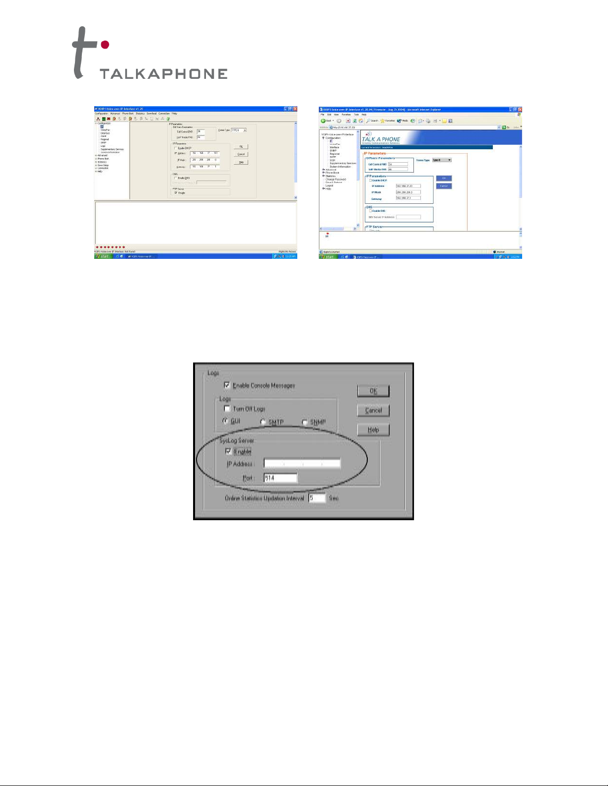
Management. Configuration and system management can be done locally with the VOIP-1-2-4-8
configuration software via a serial connection. After an IP address has been assigned locally, other
configuration can be done remotely using the Web Interface GUI. All of these control software packages
are included on the VOIP-1-2-4-8 CD.
While the Web GUI’s appearance differs slightly, its content and organization are essentially the same as
that of the Windows GUI (except for logging).
The primary advantage of the Web GUI is remote access for control and configuration. The controller PC
and the VOIP-1-2-4-8 unit itself must both be connected to the same IP network and their IP addresses
must be known.
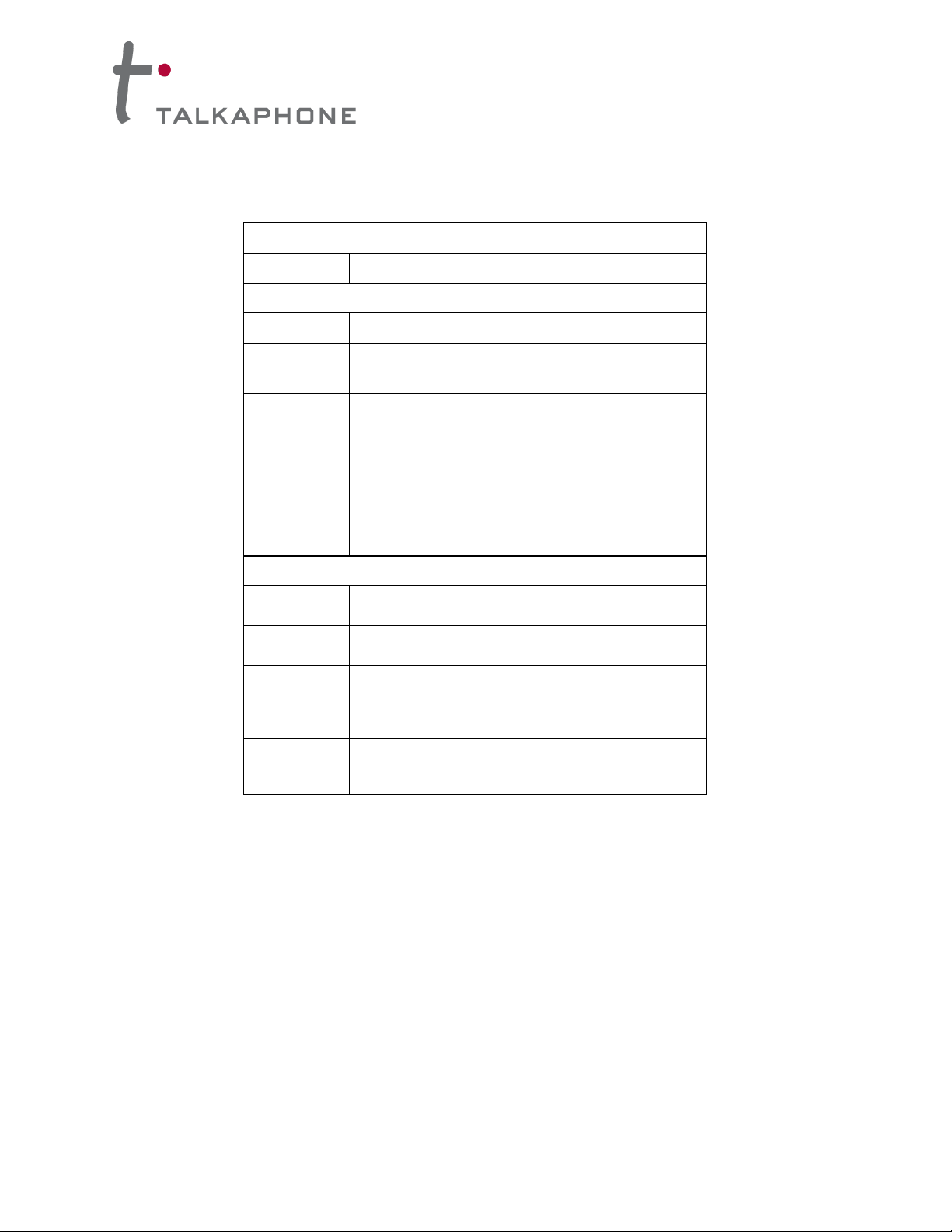
The Windows GUI gives access to commands via icons and pulldown menus, whereas the Web GUI
does not. The Web GUI, however cannot perform logging in the same direct mode done in the Windows
GUI. However, when the Web GUI is used, logging can be done by e-mail (SMTP).

VOICE OVER IP INTERFACE
Installation and Operation Manual
4
Figure 1-4: VOIP Interface Windows GUI (left) and Web Interface GUI (right)
Once you’ve begun using the web browser GUI, you can go back to the Windows GUI at any time.
However, you must log out of the web browser GUI before using the Windows GUI.
Logging of System Events. The software for the VOIP-1-2-4-8 units has SysLog Server functionality.
SysLog is a de facto standard for logging events in network communication systems.
Figure 1-5: Syslog Functionality in VOIP-1-2-4-8 Interface Units
The SysLog Server resides in the VOIP-1-2-4-8 unit itself. To implement this functionality, you will need a
SysLog client program (sometimes referred to as a “daemon”).
Supplementary Telephony Services. The H.450 standard (an addition to H.323) brings to VoIP
telephony more of the premium features found in PSTN and PBX telephony. VOIP-1-2-4-8 units offer five
of these H.450 features: Call Transfer, Call Hold, Call Waiting, Call Name Identification (not the same as
Caller ID), and Call Forwarding. (The first four features are found in the “Supplementary Services”
window; the fifth, Call Forwarding, appears in the
Add/Edit Inbound phonebook screen.) Note that the first three features are closely related. All of these
H.450 features are supported for H.323 operation only; they are not supported for SIP or SPP.

VOICE OVER IP INTERFACE
Installation and Operation Manual
5
VOIP-1-2-4-8 Front Panel LEDs
LED Types. The VOIP-1-2-4-8 units have two types of LEDs on their front panels:
(1) general operation LED indicators (for power, booting, and Ethernet functions), and
(2) channel operation LED indicators that describe the data traffic and performance in each VoIP
data channel.
Active LEDs. On both the VOIP-4 and VOIP-8, there are eight sets of channel-operation LEDs.
However, on the VOIP-4, only the lower four sets of channel-operation LEDs are functional. On the VOIP-
8, all eight sets are functional.
Figure 1-6. VOIP-4/VOIP-8 LEDs
Similarly, the VOIP-2 has the general-operation indicator LEDs and two sets of channel-operation LEDs,
one for each channel.
Figure 1-7. VOIP-2 LEDs
Finally, the VOIP-1 has the general-operation indicator LEDs and a set of channel-operation LEDs for its
single VoIP channel.
Figure 1-8. VOIP-1 LEDs

VOICE OVER IP INTERFACE
Installation and Operation Manual
6
VOIP-1 LED Description
VOIP-1 Front Panel LED Definitions
LED NAME
DESCRIPTION
General Operation LEDs
Power
Indicates presence of power.
Boot
After power up, the Boot LED will be on briefly while the
VOIP-1 is booting. It lights whenever the VOIP-1 is booting or
downloading a setup configuration data set.
Ethernet
FDX. LED indicates whether Ethernet connection is half-
duplex or full-duplex (FDX) and, in half-duplex mode,
indicates occurrence of data collisions. LED is on constantly
for full-duplex mode; LED is off constantly for half-duplex
mode. When operating in half-duplex mode, the LED will flash
during data collisions. LNK. Link/Activity LED. This LED is lit if
Ethernet connection has been made. It is off when the link is
down (i.e., when no Ethernet connection exists). While link is
up, this LED will flash off to indicate data activity.
Channel-Operation LEDs
TX
Transmit. This indicator blinks when voice packets are being
transmitted to the local area network.
RX
Receive. This indicator blinks when voice packets are being
received from the local area network.
XS
Transmit Signal. This indicator lights when the FXS-
configured channel is off-hook or the FXO-configured channel
is receiving a ring from the Telco or PBX.
RS
Receive Signal. This indicator lights when the FXS-
configured channel is ringing or the FXO-configured channel
has taken the line off-hook.

VOICE OVER IP INTERFACE
Installation and Operation Manual
7
VOIP-2-4-8 LED Descriptions
VOIP-2/VOIP-4/VOIP-8 Front Panel LED Definitions
LED NAME
DESCRIPTION
General Operation LEDs (one set on each VoIP Interface model)
Power
Indicates presence of power.
Boot
After power up, the Boot LED will be on briefly while the
VOIP-2-4-8 is booting. It lights whenever the VOIP-2-4-8 is
booting or downloading a setup configuration data set.
Ethernet
FDX. LED indicates whether Ethernet connection is half-
duplex or full-duplex (FDX) and, in half-duplex mode,
indicates occurrence of data collisions. LED is on constantly
for full-duplex mode; LED is off constantly for half-duplex
mode. When operating in half-duplex mode, the LED will flash
during data collisions. LNK. Link/Activity LED. This LED is lit if
Ethernet connection has been made. It is off when the link is
down (i.e., when no Ethernet connection exists). While link is
up, this LED will flash off to indicate data activity.
Channel-Operation LEDs (one set for each channel)
XMT
Transmit. This indicator blinks when voice packets are being
transmitted to the local area network.
RCV
Receive. This indicator blinks when voice packets are being
received from the local area network.
XSG
Transmit Signal. This indicator lights when the FXS-
configured channel is off-hook, the FXO-configured channel
is receiving a ring from the Telco, or the M lead is active on
the E&M configured channel. That is, it lights when the VOIP-
2-4-8 is receiving a ring from the PBX.
RSG
Receive Signal. This indicator lights when the FXS-
configured channel is ringing, the FXO-configured channel
has taken the line off-hook, or the E lead is active on the
E&M-configured channel.

VOICE OVER IP INTERFACE
Installation and Operation Manual
8
Computer Requirements
Minimum Requirements for Windows GUI:
The computer on which the VOIP-1-2-4-8 units’ configuration program is installed must meet these
requirements:
•must be IBM-compatible PC with MS Windows operating system
•must have an available COM port for connection to the VOIP-1-2-4-8 unit
However, this PC does not need to be connected to the VOIP-1-2-4-8 unit permanently. It only needs to
be connected when local configuration and monitoring are done. Nearly all configuration and monitoring
functions can be done remotely via the IP network.
You will need an available COM port on the controller PC. You’ll need to know which COM port is
available for use with the VOIP-1-2-4-8 (COM1, COM2, etc.).
Minimum Requirements for Web GUI
•Local Windows GUI must have been used to assign IP address to VOIP-1-2-4-8.
•Internet Explorer 6.0 or higher; or Netscape 6.0 or higher
•Java Runtime Environment version 1.4.0_01 or higher
Placement
Mount your VOIP-1-2-4-8 in a safe and convenient location where cables for your network and phone
system are accessible.

VOICE OVER IP INTERFACE
Installation and Operation Manual
9
Specifications for VOIP-1-2-4-8 Units
Contents: The VOIP-1-2-4-8 includes the following:
•VOIP unit
•120VAC power supply
•19” EIA rack-mount brackets (VOIP-4 and VOIP-8 only)
Model
VOIP-1
VOIP-2
VOIP-4
VOIP-8
Operating
Voltage/Current
100-240VAC
1.0 A
External
transformer:
3A @5V
100-240 VAC
1.2 - 0.6 A
100-240 VAC
1.2 - 0.6 A
Main Frequencies
50/60 Hz
50/60 Hz
50/60 Hz
50/60 Hz
Power Consumption
9.7 watts (with
phone off hook)
19 watts
29 watts
46 watts
Mechanical
Dimension
4.3" W x 5.6" D
1.0" H
6.2” W x
9” D x
1.4” H
1.75” H x
17.4” W x
8.5” D
1.75” H x
17.4” W x
8.5” D
10.8 cm W x
14.2 cm D x
2.95 cm H
15.8cm W x
22.9cm D x
3.6cm H
4.5cm H x
44.2 cm W x
21.6 cm D
4.5cm H x
44.2 cm W x
21.6 cm D
Weight
8 oz. (23 g)
1.8lbs (.82kg)
2.6lbs (1.17kg)
with transformer
7.1 lbs. (3.2 kg)
7.7 lbs. (3.5 kg)
Identify Remote VOIP Site to Call
When you’re done installing the VOIP-1-2-4-8, you’ll want to confirm that it is configured and operating
properly. To do so, it’s good to have another VoIP unit that you can call for testing purposes. You’ll want
to confirm end-to-end connectivity. You’ll need IP and telephone information about that remote site. If this
is the very first VoIP unit in the system, you’ll want to coordinate the installation of this VOIP-1-2-4-8 with
an installation of another unit at a remote site.
Identify VOIP Protocol to be Used
Will you use H.323, SIP, or SPP? Each has advantages and disadvantages. Although it is possible to
mix protocols in a single VOIP system, it is highly desirable to use the same VOIP protocol for all VOIP
units in the system.

VOICE OVER IP INTERFACE
Installation and Operation Manual
10
Hookup for VOIP-1
Figure 1-9: Sample hookup diagram for VOIP-1 Interface Unit
Hookup for VOIP-2
Figure 1-10: Sample hookup diagram for VOIP-2 Interface Unit
CH1
CH2

VOICE OVER IP INTERFACE
Installation and Operation Manual
11
Hookup for VOIP-4 and VOIP-8
Connect the VOIP-4 or VOIP-8 as indicated in the following diagram. Connect the RJ-11 cables from the
emergency phone(s), PSTN line(s), or analog extension(s) of the PBX to the ports labeled “FXS/FXO”.
Make sure to connect the chassis to Earth Ground at the grounding screw as indicated (VOIP-2, VOIP-4,
and VOIP-8 only)
Figure 1-11: Sample hookup diagram for VOIP-4/VOIP-8 Interface Unit
Operation
When the VOIP unit is powered on, it will take approximately one minute to boot up. The red LED
(second from the left) indicates that the unit is still booting. After the red LED clears, allow an extra
twenty seconds to ensure the unit has fully booted before attempting to initiate a call.
The emergency phones will need to be programmed in accordance with the instructions in the Quick
Start section in Chapter 2.

VOICE OVER IP INTERFACE
Installation and Operation Manual
12
VoIP System Design
Before you begin programming the VOIP Interface units, it is recommended that you plan out your system
layout. You should begin by choosing a setup type. There are two basic types of VoIP setups we can
design for an emergency phone system:
Figure 1-12: One-to-One Configuration
(1) The first setup type is a one-to-one configuration. In this scenario, each emergency phone has
its own PBX extension or phone line. The number of calls that the head end is capable of receiving
is equal to the number of emergency phones in the field.
Figure 1-13: Many-to-One Configuration
(2) The second setup type is a many-to-one configuration. In this scenario, many Emergency Phones
share PBX extensions or phone lines. The number of calls that the head end is capable of receiving is
less than the number of emergency phones in the field.
Once you have chosen a setup type, it is recommended that you assign phone numbers/PBX extensions
to the emergency phones and IP addresses to the VOIP units before programming any of the VOIP units.
Keep in mind that the PBX extension assignments are separate from the VOIP phone book extensions.
Please reference Phone Book Design (p. 18) for more information.
When designing your system layout, please keep in mind that All VOIP units must have fixed IP
addresses. Also, ensure that the proper routing and switching hardware (routers, hubs, firewalls, VPNs,
etc.) are in place for the VOIP units to communicate. It is critical that ensure network reliability, which
includes sufficient bandwidth and minimizes packet loss and packet delays.
IMPORTANT NOTE: For the Emergency Phone System to work through a power outage, all components of
the data path (i.e. the VOIP units, routers, hubs, switches, etc.) must be on back-up power.

VOICE OVER IP INTERFACE
Installation and Operation Manual
13
The following are examples of other types of VoIP setups you can design.
Figure 1-14: Many-to-One IP-Native Head End Configuration
(3) Figure 1-14 is an example of a configuration with a completely IP-native head end. With the IP-native
PBX, there isn’t a need for VOIP units at the head end.
Figure 1-15: One-to-One Closed Configuration
(4) Figure 1-15 is an example of a closed configuration with no PBX or PSTN lines. This configuration
type relies solely on the network infrastructure for call routing.
IMPORTANT NOTE: For the Emergency Phone System to work through a power outage, all components of
the data path (i.e. the VOIP units, routers, hubs, switches, etc.) must be on back-up power.

VOICE OVER IP INTERFACE
Installation and Operation Manual
14
CHAPTER 2:
Quick Start Guide for VOIP-1-2-4-8 Units
Download VOIP-1-2-4-8 Configuration Software
You can download the configuration and firmware update utility by following one of the links below or by
going to the product page at www.talkaphone.com/products/
VOIP-1: www.talkaphone.com/sites/default/files/software/VOIP-1-2-4-8/voip-1.zip
VOIP-2-4-8: www.talkaphone.com/sites/default/files/software/VOIP-1-2-4-8/voip-2-4-8.zip
Install VOIP-1-2-4-8 Configuration Software onto a PC
1. VOIP-1-2-4-8 must be properly cabled. Power must be turned on.
2. Extract the content of either “voip-1.zip” or “voip-2-4-8.zip” depending on the model used.
Open the extracted folder and double-click on the autorun.exe icon.
3. At first dialog box, click on Install Software.
4. If you will be configuring the VOIP unit remotely from the network and the PC does not have
the Java Runtime Environment installed, highlight Java and click OK. Otherwise, skip to
Step (7).
5. Follow the on-screen instructions to properly install the Java Runtime Environment.
6. Click on Install Software under the autorun.exe that was launched in Step (2).
7. Highlight either VOIP-1 Software or VOIP-2-4-8 Software and click OK.
8. At the “Welcome” screen, click Next.
9. Follow on-screen instructions. Accept default program folder location and click Next.
10. Accept default icon folder location. Click Next. Files will be copied.
11. At completion screen, click Finish.
12. At the prompt “Do you want to run VOIP-1-2-4-8 Configuration?,” click No. Software
installation is complete.
13. Go to Start !All Programs !VOIP-1 or VOIP-2-4-8 !Configuration Port Setup. Select
the proper COM port that will be used to configure the VOIP unit.
Notes on the Configuration of VOIP-1-2-4-8 Units
The initial configuration of the VOIP-1-2-4-8 units must be done locally using the Windows GUI.
However, all additional configurations can be done via the Web GUI once you know the IP address of the
VOIP unit being configured. The VOIP-1-2-4-8 unit can be reprogrammed remotely in almost every setup
where a computer can access the web interface GUI.
Once you have finished programming the VOIP units, you may set each of the units to request a login
and password each time the configuration software is launched. For more information on this topic,
please reference Setting a Password (pp. 38-39).
IMPORTANT NOTE: After each configuration change, make sure to hit OKAY at each screen. Once you have
completed configuring all options, make sure to also “Save Settings and Reboot”. If you do not click save and
reboot, all changes will be lost.

VOICE OVER IP INTERFACE
Installation and Operation Manual
15
Phone/IP Starter Configuration
The following are steps that Talk-A-Phone Co. recommends that you take in order to create a functional
VoIP system.
1. Open the VOIP-1-2-4-8 configuration program: Start |Programs | VOIP-x-x-x |Configuration.
2. Configuring the IP address. Go to Configuration | IP. Enter the IP parameters for your VoIP
site. Leave “Enable DHCP” unchecked unless your network setup requires DHCP.
NOTE: If a phone’s IP is established via DHCP, it can only make outgoing calls, not ingoing call,
unless it is set up to register with an H.323 gatekeeper, SIP proxy, or SPP master VOIP. Also,
your VoIP until must also specify a Gateway address in order for it to work properly even if a
Gateway will never be used.
If you will be using the VOIP-1-2-4-8 unit on an existing network, please consult your
network administrator for IP addresses, subnet mask, and gateway information. If you will
be creating a dedicated network, you may use proper private addressing (e.g. IP address
192.168.1.25, subnet mask 255.255.255.0, and a gateway 192.168.1.1).
3. If you would like to configure and operate the VOIP-1-2-4-8 unit using the web browser GUI,
continue on to step (4). The Web GUI has the same functionality as the local Windows GUI, but
offers remote access. If you would like to continue with the Windows GUI, skip to step (5).
4. Enable Web browser GUI (Optional). To do configuration and operation procedures using the
web browser GUI, you must first enable it. Once you’ve begun using the web browser GUI, you
can go back to the Windows GUI at any time. However, you must log out of the web browser GUI
before using the Windows GUI. To do so, follow these steps:
a. Close the Windows GUI.
b. Make sure Java Runtime Environment 1.4.2_01 or greater is installed.
c. Launch a compatible web browser (Internet Explorer 6.0 or above; or Netscape 6.0 or
above).
d. IMPORTANT NOTE: The PC being used must be connected to and have an IP address
on the same
e. IP network of the VOIP unit.
f. Browse to IP address of the VOIP unit being configured.
g. If a username and password have been established, enter them when prompted.
h. Use web browser GUI to configure VOIP unit.
5. Go to Configuration | Voice/Fax. Select Coder | “Manual.” Choose “G.711 u-law @ 64kbps” as
the Selected Coder from the pulldown menu. Talkaphone recommends G.711 u-law for
maximum line quality. It is especially recommended that this coder be selected when Talk-A-Lert
will be used with VoIP.
Under DTMF, select “Inband” from the DTMF pulldown menu.
IMPORTANT NOTE: After each configuration change, make sure to hit OKAY at each screen. Once you have
completed configuring all options, make sure to also “Save Settings and Reboot”. If you do not click save and
reboot, all changes will be lost.

VOICE OVER IP INTERFACE
Installation and Operation Manual
16
Under Advanced Features, make sure that Silence Compression is “unchecked”.
Under Automatic Disconnection, set the Call Duration to “3600” secs.
For VoIP units connected to emergency phones in a many-to-one configuration or for one-to-one
configurations (For more information on many/one-to-one configurations, see VoIP System
Design p. 12), it is recommended that you enable the Auto Call feature.
The Auto Call feature automatically links the emergency phone to the dial tone of the PBX
extension or phone line, so the emergency phone only needs to dial the extension or phone
number to reach the attendant at the head end.
Under Auto Call/OffHook Alert, select “Auto Call” from the pulldown menu and specify the
Phone Number that you would like the emergency phone to dial. Please reference Phone Book
Design (p. 18) for clarification on the phone number you should enter in this field. For head end
units of a many-to-one configuration, select “None” under Auto Call/OffHook Alert.
If you know of any other specific parameter values that will apply to your system, enter them.
Most of the time, all the channels on the multi-channel VOIP units will share the same parameter
values. To facilitate settings duplication, you can copy parameter settings from one channel to
another. Click Copy Channel.Select Copy to All. Click Copy. At the main Voice/Fax
Parameters screen, click OK to exit from the dialog box.
6. Go to Configuration | Interface. Select Interface Type | “FXS” if connecting to emergency
phones or for head end of “closed system” (ringing phone directly off head end VOIP unit without
any external phone lines or PBX), “FXO” for head end VOIP unit(s) (connecting to PBX
extensions or analog phone lines).
If the VoIP unit will be using an “FXS” interface, make sure that FXS Options | Current Loss is
“checked”. This will allow the emergency phone to hang up automatically when a call is over.
Go to Disconnect on Call Progress Tone and make sure that it is “checked”.
Under Flash Hook Options, set the Detection Range to a minimum of “100” ms and a maximum
of “150” ms.
If you know of any other specific parameter values that will apply to your system, enter them.
Most of the time, all the channels on the multi-channel VOIP units will share the same parameter
values. To facilitate settings duplication, you can copy parameter settings from one channel to
another. Click Copy Channel.Select Copy to All. Click Copy. At the main Voice/Fax
Parameters screen, click OK to exit from the dialog box.
7. Go to Configuration | Regional Parameters. Select Custom from the Country/Region
pulldown menu. Now change the entries for the following types:
Unobtainable Tone: Survivability Tone:
Frequency 1 = 480 Frequency 1 = 480
Frequency 2 = 620 Frequency 2 = 620
Cadence 1, 2, 3, 4 = 500 Cadence 1, 2, 3, 4 = 500
Reorder Tone:
Frequency 1, 2 = 999
Cadence 1, 2, 3, 4 = 0

VOICE OVER IP INTERFACE
Installation and Operation Manual
17
These settings should be similar to that for USA except for the above changes.
Click OK to exit from the Regional Parameters dialog box.
8. SMTP Configuration. You can configure the VOIP units to send e-mail notifications. If you
would like to receive phone-call logs from the VOIP-1-2-4-8 via e-mail (to your VoIP Administrator
or someone else), continue with step (9). If not, skip to step (10).
9. Go to Configuration | SMTP. SMTP allows you to send phone-call log records to the VoIP
Administrator via e-mail. Check Enable SMTP. You should have already obtained an e-mail
address for the VOIP-1-2-4-8 unit itself (this serves as the origination e-mail account for e-mail
logs that the VOIP-1-2-4-8 can e-mail out automatically).
Enter this e-mail address in the “Login Name” field. Type the password for this e-mail account.
Enter the IP \address of the e-mail server where the VOIP-1-2-4-8’s e-mail account is located in
the “Mail Server IP Address” field.
Typically the e-mail log reports are sent to the VoIP Administrator but they can be sent to any e-
mail address.
Decide where you want the e-mail logs sent and enter that e-mail address in the “Recipient
Address” field. Whenever e-mail log messages are sent out, they must have a standard Subject
line (e.g. “Phone Logs for VoIP N”). If you have more than one VOIP-1-2-4-8 unit in the building,
you’ll need a unique identifier for each one (select a useful name or number for “N”). In this
“Subject” field, enter a useful subject title for the log messages.
In the “Reply-To Address” field, enter the e-mail address of your VoIP Administrator.
10. Go to Configuration | Logs. Select “Enable Console Messages.” To allow log reports by e-mail
(if desired), click SMTP. Click OK. To do logging with a SysLog client program, check Enable
under “SysLog Server” in the Logs screen and specify the SysLog Server’s IP Address. To
implement this function, you must install a SysLog client program.
11. Enable premium (H.450) telephony features. Go to Configuration | Supplementary
Services. Select any features to be used. For Call Hold, Call Transfer, and Call Waiting, specify
the key sequence that the phone user will press to invoke the feature. For Call Name
Identification, specify the allowed name types to be used and a caller-id descriptor.
If Call Forwarding is to be used, enable this feature in the Add/Edit Inbound Phone Book screen.
12. Naming the VoIP gateway. Go to Phone Book | Phone Book Configuration. Enter the name
you would like the VOIP unit to use. This name will be used when the Caller ID feature is
enabled.
13. Programming outbound phone book information. Go to Phone Book | Outbound Phone
Book | List Entries. Click on Add to create new entries. The Outbound phone book lists the
phone numbers or extensions the VOIP unit can call. Please reference the Phone Book Design
section (p. 18) for information and examples on how to program the phone book.
14. Programming inbound phone book information. Go to Phone Book | Inbound Phone Book
| List Entries. Click on Add to create new entries. The Inbound phone book describes the
dialing sequences that can be used to call the VOIP unit being programmed unit and how those

VOICE OVER IP INTERFACE
Installation and Operation Manual
18
calls will be directed. Please reference the Phone Book Design section (p. 18) for information
and examples on how to program the phone book.
15. Changing user name and password (Web GUI only. See p. 38 for instructions on the
Windows GUI). Go to Change Password. Specify the User Name that you would like to use
for this VOIP unit.
If an Old Password exists, enter that password. Now proceed with assigning a New Password
and then Reconfirm Password.
16. Save configuration changes. Go to Save Setup | Save and Reboot. Click OK. This will save
the parameter values that you have just entered. The VOIP-1-2-4-8’s “BOOT” LED will light up
while the configuration file is being saved and loaded into the VOIP-1-2-4-8. Don’t do anything to
the VOIP-1-2-4-8 until the “BOOT” LED is off (a loss of power at this point could cause the VOIP-
1-2-4-8 unit to lose the configuration settings you have made).

VOICE OVER IP INTERFACE
Installation and Operation Manual
19
Phone Book Design
Phone book entries are critical when designing a VoIP setup for Emergency Phones. The phone book in
the VOIP units serve in providing routing information for calls over a Voice-over IP setup. The Outbound
phone book for a particular VOIP unit describes the dialing sequences required for a call to originate
locally and reach any of its possible destinations at remote VoIP sites. The Inbound phone book for a
particular VoIP unit describes the dialing sequences required for a call to originate remotely from any
other VOIP sites in the system, and to terminate on that particular VOIP.
Concisely, the Outbound phone book lists the phone stations it can call and the Inbound phone book
describes the dialing sequences that can be used to call that VOIP unit and how those calls will be
directed. In general, the Inbound phone book entries of the local VOIP unit will match the Outbound
phone book entries of the remote VOIP unit. Similarly, the Outbound phone book entries of the local
VOIP unit will match the Inbound phone book entries of the remote VOIP unit. However, in most cases,
the VOIP units will only have some matching entries.
Once you’ve programmed the VOIP units with a known IP address, you can remotely program the phone
books of each unit through the Web GUI. The following steps will assist you in completing the task of
programming the phone book(s).
1. Open a web browser to the VOIP-1-2-4-8 to be configured to access the Web GUI. Go to
Phone Book.
2. Under Outbound Phone Book, add entries for the extensions and IP addresses for each
emergency phone or extension/phone number that the VOIP unit will call. It is advised that
every entry be configured for the H.323 protocol.
To add an entry, click on Add. Enter the extension/phone number to be dialed in the
Destination Pattern field. Specify the Total Digits and the IP Address to which that
number is assigned.
You can now continue configuring other parameters such as SIP proxy and H.323 gateway
information. Click OK once you have completed configuring this entry. You should repeat
step (2) for all outbound phone book entries.
3. Under Inbound Phone Book, add entries for the dialing sequences that can be used to call
the VOIP unit being configured.
To add an entry, click on Add. Enter the extension/phone number to be dialed in the
Remove Prefix field. Under Channel Number, make sure that it is not set for “Hunting”
mode. Assign a Channel Number to each extension/phone number to a port on the multi-
channel VOIP units (VOIP-2, VOIP-4, VOIP-8).
You can now continue configuring other parameters such as Call Forward. Click OK once
you have completed configuring this entry. You should repeat step (3) for all inbound phone
book entries.

VOICE OVER IP INTERFACE
Installation and Operation Manual
20
Phone Book Design Example 1
In Figure 2-1, we have a one-to-one configuration. Each emergency phone will have an assigned
PBX extension, so the head end VOIP-4 will only be using three of its four channels. Also, in this
scenario, the PBX is set to ringdown mode, so every emergency phone is programmed with *13*5*
and each VOIP unit connected to an emergency phone is configured to auto call/hotline to the
attendant phone.
Figure 2-1: Example of a one-to-one VoIP System Configuration
For the VOIP units connected to emergency phones, we would program the phone books with the
following information.
Emergency Phone 1:
Inbound Phone Book entry: 101
Outbound Phone Book entry: 201 assigned to 192.168.37.40
Emergency Phone 2:
Inbound Phone Book entry: 102
Outbound Phone Book entry: 202 assigned to 192.168.37.40
This manual suits for next models
3
Table of contents
Other Talkaphone Recording Equipment manuals