Talon TP-50BS User manual
TP-50BS (Rev 1.0)
TALON TECH CO. LTD.
Pump for PR Dispense High Viscosity Pump
TALON TECH CO. LTD.
MODEL : TP-50BS

TP-50BS (Rev 1.0)
TALON TECH CO. LTD.
1. System Configurations……………………………….………………………………………………………………………………………….
1
2. System Specifications…………………………………………………………………………………………………………………………….
2
2-1. Pump [TP-50BS]…….………………………………………………………………………………………………………………………….
2
2-2. Controller [TPC-5002].………..…………………………………………………………………………………………………………….
3
2-3. Touch Pad [TTP-5016]……………………………………………………………………………………………………………………….
3
3. System In/Exterior Names…….………………………….…………………………………………………………………………………..
4
3-1. Pump Exterior Names…………………………………………………………………………………………….…………………………
4
3-1-1. Pump Name Explanation……………………………………………………………………………………….………………….
4
3-2. Controller Exterior Names....…………………………………………………………………………………………………………..…
5
3-2-1. Controller Name Explanation..……..…………………………………………………………………………………………...
5
3-3. Touch Pad Exterior Names..……..………………………………………………………………………………..……………………..
7
3-3-1. Touch Pad Name Explanation.……..…………………………………………………………..………………………………..
7
4. Track/Auxiliary Interface………….……………………………………………………………………………………………………………
8
4-1. Track Interface Signal……….……………………………………………………………………………………………………………….
8
4-2. Track Interface Wiring……………………………………...……………………………………………………………………………….
9
4-3. Cable Pin Assign……………..………………………………………………………………………………………………………………..
10
5. External Cable Length……………………………………………………………………………………………………………………………
12
5-1. Pump Cable..……………………………………………………………………………………………………………………………………..
12
5-2. Track Cable………………………………………………………………………………………………………………………………………..
12
5-3. Touch Pad Cable……..………………………………………………………………………….………………………………………….…
13
6. Touch Pad Operation……………………………………………………………………………………………………………………………..
14
6-1. Operation……………………………………………………………………………………….…………………………………………………
14
6-1-1. Initial Screen ………………………………………………………………………….………………………………………………….
14
6-1-2. Pump Condition Indicate In Use..…..…………………………………………………………………………………………
14
6-1-3. Select Function…….…………………………………………………...……………………………………………………………….
14
6-1-4. Dispense…………………………………………………………………………………………………………………………………….
15
6-1-5. Recipe Setting……………………………………………………………………………………………………………………………
15
6-1-6. Configuration of Pump……………………………………………………………………………………………………………...
16
6-1-6-1. ID Setting………………….………………………………………………………………………………………………………...
16
6-1-6-2. Maint Mode, Run Mode, Pump Reset Setting……….………………………………………………………….
16
6-1-7. Calibration………………………………………………………………………………………………………………………………….
16
6-2. Example..……..…………………………………………………………………………………………………………………………………….
17
6-2-1. Dispense Test….………………………………………………………………………………………………………………………….
17
CONTENTS

TP-50BS (Rev 1.0)
TALON TECH CO. LTD.
6-2-2. Recipe Setting……………………………………………………………………………………………………………………………
18
6-3. Cycle Purge Method…………………………...……………………………………………………………………………………………
19
6-4. Reset on Pump Error……..………….………..…………………………………………………………………………………………….
21
6-5. Touch Pad Menu Tree……………………………………………………………………………………………………………………….
22
6-6. Notice………………………………………………………………………………………………………………………………………………..
22
6-6-1. Dispense Cycle………………………..…..……………………………………………………………………………………………..
22
6-6-2. Pump ID Setting……………..…………………………………………………………………………………………………………
22
6-6-3. Recipe Setting………………………………………………………………………………………………….………………………...
22
6-7. Notice on Pump Operation.………….………………………………………………………………………………………….………
23
7. Maintenance……………………………………………...……………………………………………………………………………………………
24
7-1. Manual Purge Method……….…………………………………………………………………………………………………………….
24
7-2. Suck-Back Setting………….………………………………………………………………………………………………………………….
25
8. Recommended Spares/Mechanical Dimensions…………..……………………………………………………………………..
27
8-1. TP-50BS Spare Parts…………………………..……………………………………………………………………………………………..
27
8-2. Pump Dimensions………………….…………………………………………………………………………………………………………
28
8-2-1. Front/Rear View……………………………………………………………………………………………….………………………...
28
8-2-2. Side View………...………….……………………………………………………………………………………………………………...
28
8-3. Controller Dimensions……..…………………………………………………………………………………….………………………...
29
8-3-1. Front View………………………….…………………………………………………………………………….………………………...
29
8-3-2. Rear View………………….…...……..……………………………………………………………………………………………………
29
8-3-3. Side View………………….……………………..………………………………….……………………………………………………...
29
8-4. Touch Pad Dimensions…………………………..………………………………….……………………………………………………...
30
8-4-1. Front View……………………...…………………………………………………………………………………………………………..
30
8-4-2. Rear View…………………...………………………………………………………………………………………………………………
30
8-4-3. Side View………………..……………………..…………………………………………………………………….……………………..
30
8-5. Installation Method……………………………..…………………………………………………………………….……………………..
31
8-5-1. Pump Installation Sequence.……..……………………………………………………………………………………………...
31
8-5-2. Piping Method………..…….…………………………………………………………………………………………………………...
31
8-5-3. Touch Pad Installation Method…………..……………………………………………………………………………………..
32
8-5-4. Suggested Recipe Setting Value………….……………………………………………………………………………………
33

TP-50BS (Rev 1.0)
- 1 -
TALON TECH CO. LTD.
TP-50BS pump can be used as the above configuration and has been developed for the semiconductor
system’s automation by operating RS422 communication. Especially, the adoption of servo motor is good
for the high degree of PR dispense. The basic communication between the touch pad and the pump is
RS422 Multi Drop method. By synchronizing with Windows CE Operating System, Touch Pad MMI 2.0
Software operates TP-50BS pump.
Be careful to use the pump by following this manual or Talon Tech’s acceptance. Or, other defects
should be paid even under the warranty period.
※Features & Merits
1. All the PR contacting points are made by Teflon.
2. Driving Method : Diaphragm & bubble trap technology.
3. Micro bubble control : Special Welding, no leak point.
4. Touch pad has the same function of controller & it can control up to 16 pumps.
5. Encompass or Normal trigger signal.
6. Compact sized resist pump and controller. (1 Controller covers 2 pumps)
System Configurations
1
TPC-5002 Controller
2 Pump Control
Wafer
Dispense Nozzle
Suck-Back V/V
PR Bottle
TP-50BS Pump
Touch Pad
Max 16ea
Pump Control
Pump 1
Pump 2
AC85~264V
50/60Hz

TP-50BS (Rev 1.0)
- 2 -
TALON TECH CO. LTD.
\
2-1 Pump [ TP-50BS ]
ITEM
SPEC
REMARKS
Dispense Volume Range
1.0cp ~ 7cc
Dispense Volume Resolution
±0.01cc
Dispense / Reload Rate
0.3cc/sec ~ 1.2cc/sec
Dispense Repeatability
≤±0.04 (Polyimide PIX/PIQ)
Viscosity
200cp ~ 20,000cp
Drive System
DC Servo Motor
Pump Type
Diaphragm Type
Ambient Temperature
5 ∼40 ℃
Motor Power
DC 24V (current consumption : 1A)
Air
0.1 ~ 0.3Mpa
Resist In/Out
3/8 Inch Teflon
Weight
6.30kg
Pump Dimension
W : 97mm, D : 291mm, H : 362mm
System Specifications
2
TP-50BS (Rev 1.0)
- 3 -
TALON TECH CO. LTD.
2-2 Controller [ TPC-5002 ]
ITEM
SPEC
REMARKS
Electric Power
85VAC ~ 264VAC, 50~60Hz
Controller Power
DC 24V (current consumption Max 1A)
Panel Use
Drive Pump No.
2 Pumps
Pump Operation Mode
Fixed Mode
Main CPU
80c296 (16bit Processor)
Input Signal
1. Pump Driving Signal From Track M/C- Pump
Start Signal.
Output Signal
1. Home Signal & Pump Operation Completion
Signal To Track M/C.
2. Air V/V controlled Sol V/V Signal.
3. Alarm Signal on Pump Error.
4. Outside Communication (RS 232,422,485).
Weight
3.30kg
Dimension
W : 250mm, D : 261mm, H : 94mm
2-3 Touch Pad [ TTP-5016 ]
ITEM
SPEC
REMARKS
Main CPU
32Bit ARM920T
Ram
64Mb (OS:32Mb/App:32Mb)
Flash
NAND Flash 64Mb (OS:32Mb/App:32Mb)
LCD Size
4.3 Inch TFT Wide (480*272)
RTC Function Built-in
Exchangeable Coin Battery
Max. Connecting Pump No.
16 Pumps
Communication
RS422
Touch Pad Power
DC12~24V, current consumption: 5W (400~700mA)
Ambient Temperature
-10 ~ 55C
Weight
0.64kg
Dimension
W : 140mm, D : 44mm, H : 88mm

TP-50BS (Rev 1.0)
- 4 -
TALON TECH CO. LTD.
3-1 Pump In/Exterior Names
3-1-1 Pump Name Explanation
①PR Out
- Chemical Dispense. (⅜Inch Teflon)
②PR In
- Chemical Supply. (⅜Inch Teflon)
③PR Drain
- Chemical Drain. (⅜Inch Teflon)
④Toggle Valve
- One Touch Toggle Valve for chemical drain.
⑤Buffer Tank
- Bubble removal and buffering function
⑥Pump Connector
- Pump to Controller. Connector for Pump Operation. (D-SUB 15P Female)
System In/Exterior Names
3
⑤Buffer Tank
③PR Drain
④Toggle Valve
②PR In
①PR Out
⑥Pump Connector

TP-50BS (Rev 1.0)
- 5 -
TALON TECH CO. LTD.
3-2 Controller Exterior Names
3-2-1 Controller Name Explanation
①CH-1 In Sol S/W
- After CH-1 Pump Dispense, LED Lamp Switch for Reload Operation Condition.
②CH-1 Out Sol S/W
- After CH-1 Manual Purge, Suck-Back Valve On-Switch.
③CH-2 In Sol S/W
- After CH-2 Pump Dispense, LED Lamp Switch for Reload Operation Condition.
④CH-2 Out Sol S/W
- On CH-2 Manual Purge, Suck-Back Valve On-Switch.
⑤CH-1 Power S/W
- CH-1 Power On / Off Switch.
[TPC-5002 Front]
[TPC-5002 Rear]
①
②
③
④
⑤
⑥
⑦
⑧
⑨
⑩
⑪
⑫
⑬
⑭
⑮

TP-50BS (Rev 1.0)
- 6 -
TALON TECH CO. LTD.
⑥CH-2 Power S/W
- CH-2 Power On / Off Switch.
⑦Controller Main S/W
- Main Power Switch for controller.
⑧Main AC-IN
- AC100~220V (50 / 60Hz) Power Connector.
⑨CH-1 Pump Connector
- CH-1 Pump Connector. (D-SUB 15P Female)
⑩CH-1 Track I/O Connector
- CH-1 Track I/O Connector. (D-SUB 15P Female)
⑪CH-2 Pump Connector
- CH-2 Pump Connector. (D-SUB 15P Female)
⑫CH-2 Track I/O Connector
- CH-2 Track I/O Connector. (D-SUB 15P Female)
⑬DC 24V Connector
- Touch Pad Power Connector.
⑭COM In Connector
- Touch Pad RS-422 Communication In Connector. (D-SUB 9P Female)
⑮COM Out Connector
- Touch Pad RS-433 Communication Out Connector. (D-SUB 9P Female)
TP-50BS (Rev 1.0)
- 7 -
TALON TECH CO. LTD.
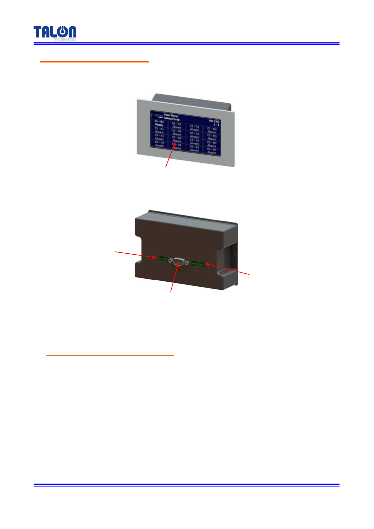
3-3 Touch Pad Exterior Names
3-3-1 Touch Pad Name Explanation
①Touch Panel
- Touching area
②Power In
- Touch Pad Power DC12~24V Connector.
③Not Use
- No Use. (D-SUB 9P Male)
④Com Port
- Touch Pad RS-422 Communication Connector.
①Touch Panel
②Power Source
(DC12~24V)
③Com Port (RS422)
④Com Port (RS422)
Table of contents
Other Talon Water Pump manuals


Popular Water Pump manuals by other brands


Sykes AmeriPumps
Sykes AmeriPumps GP100M Operation and maintenance instructions

DUROMAX
DUROMAX XP WX Series user manual

BRINKMANN PUMPS
BRINKMANN PUMPS SBF550 operating instructions

Franklin Electric
Franklin Electric IPS Installation & operation manual

Xylem
Xylem e-1532 Series instruction manual

Milton Roy
Milton Roy PRIMEROYAL instruction manual