Talon TP-70BS User manual

TP-70BS (Rev 3.0)
TALON TECH CO. LTD.
HIGH VISCOSITY & HIGH CAPACITY PR PUMPPump& Controller System
TALON TECH CO. LTD.
MODEL : TP-70BS

TP-70BS (Rev 3.0)
TALON TECH CO. LTD.
1. System Configurations……………………………….………………………………………………………………………………………….
1
2. System Specifications…………………………………………………………………………………………………………………………….
2
2-1. Pump [TP-70BS]…….………………………………………………………………………………………………………………………….
2
2-2. Controller [TPC-7002].………..…………………………………………………………………………………………………………….
3
2-3. Touch Pad [TTP-7008]……………………………………………………………………………………………………………………….
3
3. System In/Exterior Names………….…………………….…………………………………………………………………………………..
4
3-1. Pump Exterior Names….…..…………………………………………………………………………………….…………………………
4
3-1-1. Pump Name Explanation……………………………………………………………………………………….………………….
4
3-2. ControllerExterior Names……………………………………………………………………………………………………………..…
5
3-2-1. Controller Name Explanation……….…………………………………………………………………………………………...
5
3-3. Touch Pad Exterior Names.………………………………………………………………………………………..……………………..
6
3-3-1. Touch Pad Name Explanation………...………………………………………………………..………………………………..
6
4. Track/Auxiliary Interface………….……………………………………………………………………………………………………………
7
4-1. Track Interface Signal……….……………………………………………………………………………………………………………….
7
4-2. Track Interface Wiring……………………………………...……………………………………………………………………………….
8
4-3. Cable Pin Assign……………..………………………………………………………………………………………………………………..
9
4-3-1. Pump Cable……………………….………………………………………………………………………………………………………
9
4-3-2. Track Cable………………………………………….……………………………………………………………………………………..
10
4-3-3. Touch Pad Cable………………………………………………………………………………………………………………………..
12
4-3-4. COM Cable……………….………………………………………………………………………………………………………………..
12
5. External Cable Length……………………………………………………………………………………………………………………………
13
5-1. Pump Cable..……………………………………………………………………………………………………………………………………..
13
5-2. Track Cable………………………………………………………………………………………………………………………………………..
13
5-3. Touch Pad Cable……..………………………………………………………………………….………………………………………….…
14
5-4. COM Cable………………………………………………………………………………………………………………………………………..
14
5-5. Communication Cable Connection Method…….…………………………………………………………………..……….…
15
6. Touch Pad Operation……………………………………………………………………………………………………………………………..
16
6-1. Operation……………………………………………………………………………………….…………………………………………………
16
6-1-1. Initial Screen…….…………………………………………………………………….………………………………………………….
16
6-1-2. Pump Condition Indicate In Use………………….……………………………………………………………………………
16
6-1-3. Select Function…………….…………………………………………...……………………………………………………………….
17
6-1-4. Dispense…………………………………………………………………………………………………………………………………….
17
6-1-5. Recipe Setting……………………………………………………………………………………………………………………………
18
6-1-6. Config Pump……………………………………………………………………………………………………………………………...
29
CONTENTS

TP-70BS (Rev 3.0)
TALON TECH CO. LTD.
6-1-6-1. ID Setting………………….………………………………………………………………………………………………………...
19
6-1-6-2. Maint Mode, Run Mode, Pump Reset Setting……….………………………………………………………….
20
6-1-7. Calibration………………………………………………………………………………………………………………………………….
21
6-1-8. Counter……………...……………………………………………………………………………………………………………………….
21
6-2. Example………………….………………………………………………………………………………………………………………………….
23
6-2-1. Dispense Test….………………………………………………………………………………………………………………………….
23
6-2-2. Recipe Setting……………………………………………………………………………………………………………………………
24
6-2-3. ID Setting………………………………………………………………………………………………………………………….............
25
6-2-4. Name Setting………………………………………………………………………………………………………………………….....
26
6-3. Cycle Purge Method…………………………...……………………………………………………………………………………………
27
6-4. Reset on Pump Error…………………………..…………………………………………………………………………………………….
29
6-5. Log Data………..…………………………………………………………………………………………….................................................
30
6-5-1. Log Data Analysis ………..……………………………………………………………………………………………...................
31
6-6. Touch Pad Menu Tree……………………………………………………………………………………………………………………….
32
6-7. Notice……...………………………………………………………………………………………………………………………………………..
32
6-7-1. Dispense Cycle………………………..…..……………………………………………………………………………………………..
32
6-7-2. Pump ID Setting……………..…………………………………………………………………………………………………………
32
6-7-3. Recipe Setting………………………………………………………………………………………………….………………………...
32
6-8. Notice on Pump Operation.………….………………………………………………………………………………………….………
33
7. Maintenance……………………………………………...……………………………………………………………………………………………
34
7-1. Purge Method……………….………………………………………………………………………………………………………………….
34
7-2. Pump Parts Dis/Assembly.…..………..………………………………………………………………………………………………….
35
7-2-1. Pump Cover Dis/Assembly..…..…………………….……..……………………………………………………………………..
35
7-2-2. Driving Shaft Condition Check & Grease up on Ball Screw……...……………………………………………..
35
7-3. Suck-Back Setting………….………………………………………………………………………………………………………………….
36
8. Recommended Spares/Mechanical Dimensions…………..……………………………………………………………………..
38
8-1. TP-70BS Spare Parts…………………………..……………………………………………………………………………………………..
38
8-2. Pump Dimensions………………….…………………………………………………………………………………………………………
39
8-2-1. Front View…………………….………………………………………………………………………………….………………………...
39
8-2-2. Side View………...………….……………………………………………………………………………………………………………...
39
8-3. Controller Dimensions……..…………………………………………………………………………………….………………………...
40
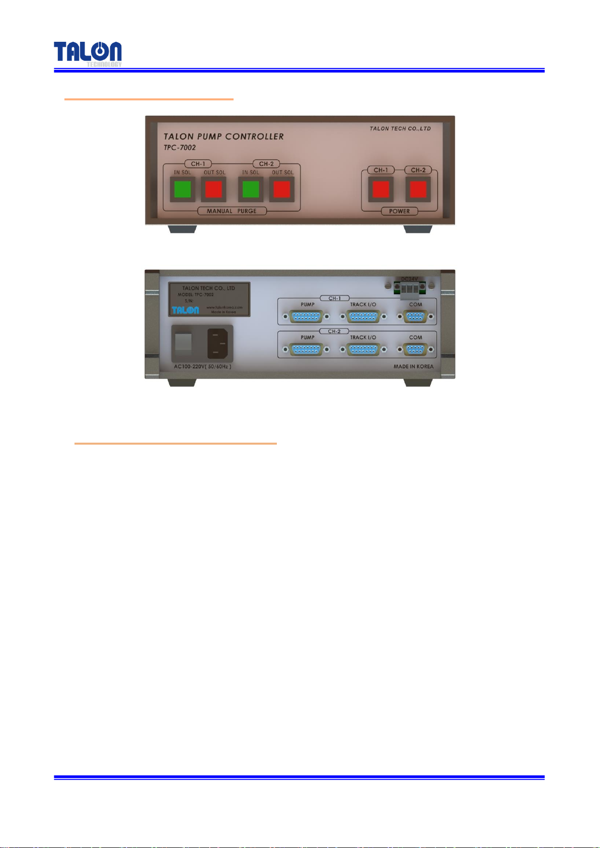
8-3-1. Front View………………………….…………………………………………………………………………….………………………...
40
8-3-2. Rear View………………….…...……..……………………………………………………………………………………………………
40
8-3-3. Side View………………….……………………..………………………………….……………………………………………………...
40
8-4. Touch Pad Dimensions…………………………..………………………………….……………………………………………………...
41
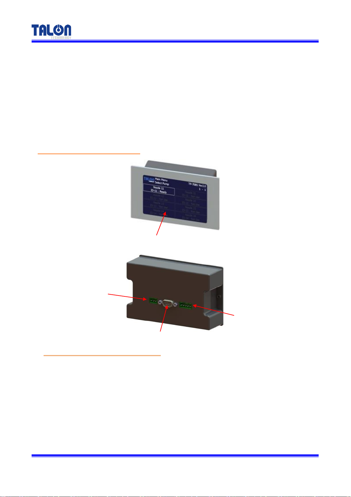
8-4-1. Front View……………………...…………………………………………………………………………………………………………..
41
8-4-2. Rear View…………………...………………………………………………………………………………………………………………
41
8-4-3. Side View………………..……………………..…………………………………………………………………….……………………..
41

TP-70BS (Rev 3.0)
TALON TECH CO. LTD.
8-5. Installation Method……………………………..…………………………………………………………………….……………………..
42
8-5-1. Pump Installation Sequence.…..………………………………………………………………………………………………...
42
8-5-2. Piping Method………..…….…………………………………………………………………………………………………………...
42
8-5-3. Touch Pad Installation Method…………..……………………………………………………………………………………..
43
8-5-4. Suggested Recipe Setting Value…………….…………………………………………………………………………………
44

TP-70BS (Rev 3.0)
- 1 -
TALON TECH CO. LTD.
TP-70BS pump can be used as the above configuration and has been developed for the semiconductor
system’s automation by operating RS422 communication. Especially, the adoption of servo motor is good
for the high degree of PR dispense. The basic communication between the touch pad and the pump is
RS422 Multi Drop method. By synchronizing with Windows CE Operating System, Touch Pad MMI 2.0
Software operates TP-70BS pump.
Be careful to use the pump by following this manual or Talon Tech’s acceptance. Or, other defects
should be paid even under the warranty period.
※Features & Merits
1. All the PR contacting points are made by Teflon
2. Driving Method:Cylinder & bubble trap technology / Outer type edgeless bellows.
3. Micro bubble control. (No Leak point)
4. Touch pad has the same function of controller & it can control upto16 pumps.
5. Encompass or Normal trigger signal.
System Configurations
1
Touch Pad
Max 16ea
Pump Control
Pump 1
Pump 2
PR Bottle
Wafer
Dispense Nozzle
Suck-Back V/V
AC85~264V
50/60Hz
TPC-7002 Controller
2 Pump Control
TP-70BS

TP-70BS (Rev 3.0)
- 2 -
TALON TECH CO. LTD.
2-1Pump[ TP-70BS ]
ITEM
SPEC
REMARKS
Dispense Volume Range
1.0cc ~ 20cc
Dispense/ Reload Rate
0.3 cc/sec ~ 1.2 cc/sec
Dispense Volume Resolution
0.01 cc
Dispense Repeatability
≤±0.04(Polyimide PIX/PIQ)
Viscosity
50cp ~ 20,000cp
Drive System
DC Servo Motor
Pump Type
Outer Type Edgeless Bellows
Motor Power
DC 24V (current consumption : 1.4A)
Air
0.1 ~ 0.3Mpa
Resist In/Out/Vent tube
⅜”Inch Teflon
Ambient Temperature
5 ∼40 ℃
Weight
6.65kg
Pump Dimension
W : 87mm, D : 299mm, H : 313mm
System Specifications
2

TP-70BS (Rev 3.0)
- 3 -
TALON TECH CO. LTD.
2-2 Controller [ TPC-7002 ]
ITEM
SPEC
REMARKS
Electric Power
85VAC ~ 264VAC, 50~60Hz
Controller Power
DC 24V (current consumption Max 1A)
Panel Use
Drive Pump No.
2 Pumps
Pump Operation Mode
Fixed Mode
Main CPU
80c296 (16bit Processor)
Input Signal
1. Pump Driving Signal From Track M/C- Pump
Start Signal.
Output Signal
1. Home Signal & Pump Operation Completion
Signal To Track M/C.
2. Air V/V controlled Sol V/V Signal.
3. Alarm Signal on Pump Error.
4. Outside Communication (RS422).
Weight
3.30kg
Dimension
W : 250mm, D : 261mm, H : 94mm
2-3 Touch Pad[ TTP-7008 ]
ITEM
SPEC
REMARKS
Main CPU
32Bit ARM920T
Ram
64Mb (OS:32Mb/App:32Mb)
Flash
NAND Flash 64Mb (OS:32Mb/App:32Mb)
LCD Size
4.3 Inch TFT Wide (480*272)
RTC Function Built-in
Exchangeable Coin Battery
Max. Connecting Pump No.
8 Pumps
Communication
RS422
Touch Pad Power
DC12~24V, current consumption: 5W (400~700mA)
Ambient Temperature
-10 ~ 55C
Weight
0.64kg
Dimension
W : 140mm, D : 44mm, H : 88mm

TP-70BS (Rev 3.0)
- 4 -
TALON TECH CO. LTD.
3-1 Pump In/Exterior Names
3-1-1 Pump Name Explanation
①PR In
- ChemicalSupply. (⅜Inch Teflon)
②PR Out
- ChemicalDispense. (⅜Inch Teflon)
③PR Drain
- Chemical Drain.(⅜Inch Teflon)
④Toggle Valve
- One Touch Toggle Valve for chemical drain.
⑤Buffer Tank
- Bubble removal and buffering function
⑥Pump CON
- Pump to Controller. Connector for Pump Operation. (D-SUB 15P Female)
SystemIn/Exterior Names
3
②PR Out ⅜”
①PR In ⅜”
④Toggle Valve
⑤Buffer Tank
⑥Pump CON
③PR Drain ⅜”

TP-70BS (Rev 3.0)
- 5 -
TALON TECH CO. LTD.
3-2 ControllerExterior Names
3-2-1 Controller Name Explanation
①CH-1 In Sol S/W
- After CH-1 Pump Dispense, LED Lamp Switch for Reload Operation Condition.
②CH-1 Out Sol S/W
- After CH-1 Manual Purge, Suck-Back Valve On-Switch.
③CH-2 In Sol S/W
- After CH-2 Pump Dispense, LED Lamp Switch for Reload Operation Condition.
④CH-2 Out Sol S/W
- CH-2 Manual Purge시Suck-Back Valve On/Off Switch.
⑤CH-1 Power S/W
- CH-1 Power On / Off Switch
⑥CH-2 Power S/W
- CH-2 Power On / OffSwitch.
⑦Controller Main S/W
- Main Power Switch for controller.
⑧Main AC-IN
- AC100~220V(50 / 60Hz) Power Connector.
⑨CH-1 Pump, Track I/O, COM
[TPC-7002Front View]
[TPC-7002Rear View]
①
②
③
④
⑤
⑥
⑦
⑧
⑨
⑩
⑪

TP-70BS (Rev 3.0)
- 6 -
TALON TECH CO. LTD.
- CH-1 Pump Connector. (D-SUB 15P Female)
- CH-1 Track I/O Connector. (D-SUB 15P Female)
- CH-1 Touch Pad RS-422 Communication Connector. (D-SUB 9P Female)
⑩CH-2 Pump, Track I/O, COM
- CH-2 Pump Connector. (D-SUB 15P Female)
- CH-2 Track I/O Connector. (D-SUB 15P Female)
- CH-2 Touch Pad RS-422 Communication Connector. (D-SUB 9P Female)
⑪DC 24V
- Touch Pad Power Connector.
3-2 Touch Pad Exterior Names
3-2-1 Touch PadName Explanation
①Touch Panel
- Touching area
②Power In
- Touch Pad Power DC12~24V Connector
③Com Port
- Touch Pad RS422 communication Connector (D-SUB 9P Male)
④Com Port
- Touch Pad RS422 communication Connector
②Power Source
(DC12~24V)
③Com Port (RS422)
④Com Port (RS422)
①Touch Panel

TP-70BS (Rev 3.0)
- 7 -
TALON TECH CO. LTD.
4-1 Track Interface Signal
Recipe Select Trigger
“0”Trigger Off
“1”Trigger On
Recipe
Select
Start1
[1]
Start2
[2]
Start3
[3]
Remark
1
1
0
0
2
0
1
0
3
1
1
0
4
-
-
-
Not support
5
1
0
1
6
0
1
1
7
1
1
1
It is Timing Chart. On Readycondition, when Start Signal becomes active, each signal is same as the
chart. When Stop Alarm occurs, all stop even during dispensing. But, the warning alarm does
dispense. The alarm becomes clear by reset after pump clear.
Track / Auxiliary Interface
4

TP-70BS (Rev 3.0)
- 8 -
TALON TECH CO. LTD.
4-2Track InterfaceWiring
<Stop / WarningActive High>
<End / Home Active Low>
<Start1, 2, 3 Active Low>
Controller Side
Track Side

TP-70BS (Rev 3.0)
- 9 -
TALON TECH CO. LTD.
4-3 Cable Pin Assign
4-3-1 Pump Cable
Pin
Number
Standard Type(D-SUB 15P)
Controller
Pump
1
+5V
1 : 1
2
PUMP_CW
1 : 1
3
PUMP_CCW
1 : 1
4
+24V
1 : 1
5
E_HOME_SIGNAL
1 : 1
6
E_END_SIGNAL
1 : 1
7
E_MOTOR_ALARM
1 : 1
8
E_MOTOR_INPOSITION
1 : 1
9
GND
1 : 1
10
GND
1 : 1
11
Not Use
1 : 1
12
EX_IN_SOL V/V +24V
1 : 1
13
E_SUCK_BACK_SOL_V/V +24V
Suck-Back Output ( + )
14
EX_IN_SOL V/V -24V
1 : 1
15
E_SUCK_BACK_SOL_V/V -24V
Suck-Back Output ( - )

TP-70BS (Rev 3.0)
- 10 -
TALON TECH CO. LTD.
4-3-2Track Cable
Pin
Number
Standard Type(D-SUB 15P)
Signal Name
I/O
Description
1
N.C
Output
Option Alarm
2
COM
Output
3
N.O
Output
4
START 3
Input
Recipe Select Signal
5
START 1
Input
6
START 2
Input
7
OUT SOL
Output
8
ALARM STOP
Output
Pump Alarm(Pump Stop)
9
ALARM WARNING
Output
Pump Alarm(Pump Run)
10
HOME
Output
Pump Ready
11
END
Output
Pump Dispense End
12
IN SIOL
Output
Reload Signal
13
MC VCC
Input
MC POWER VCC (+5V~24V)
14
START VCC
Input
Dispense Trigger(+5~24V)
15
MC GND
Input
MC POWER GND
Pin
Number
Track Cable(D-SUB 15P)
N2 Type
Connecting Way
Controller
Track (ACT-12)
Track(ACT-12)
1
N.C
Not Use
Alarm is only for Stop. After
disconnecting EXT High 5,
link NO/COM with EXT 2P
cable.
Dispense Trigger links Suck-
Back V/V Cable from the
system after checking (+, -).
2
COM
EXT High 5 (link after disconnect)
3
N.O
EXT High 5 (link after disconnect)
4
START 3
Not Use
5
START 1
Dispense Trigger ( - ) 2P
6
START 2
Not Use
7
OUT SOL
Not Use
8
ALARM STOP
Not Use
9
ALARM WARNING
Not Use
10
HOME
Not Use
11
END
Not Use
12
IN SOL
Not Use
13
MC VCC
Not Use
14
START VCC
Dispense Trigger(+5~24V) 2P
15
MC GND
Not Use

TP-70BS (Rev 3.0)
- 11 -
TALON TECH CO. LTD.
Pin
Number
Encompass Type(Hirose 20P)
Controller
Track (ACT-12)
Connecting Way
1
Not Use
X
Pump I/O Board
↓
Pump I/O CONN Board
↓
I/F Board
↓
CN3, 4, 6, 7
↓
J164~167(Track1~4)
(Refer to Electric Diagram)
2
Not Use
X
3
Not Use
X
4
Not Use
X
5
START 1
18
6
START 2
17
7
OUT SOL V/V
6 => Jump to END 7
8
ALARM STOP
5
9
ALARM WARNING
4
10
HOME
3
11
END
7 => Jump from 6
12
IN SOL V/V
8
13
+5VA
2
14
MC POWER
15
GND
20

TP-70BS (Rev 3.0)
- 12 -
TALON TECH CO. LTD.
4-3-3 Touch Pad Cable
4-3-4COM Cable

TP-70BS (Rev 3.0)
- 13 -
TALON TECH CO. LTD.
5-1 Pump Cable
5-2Track Cable
External Cable Length
5
ACT Type
Standard Type
Mark Type
ACT Encompass Type

TP-70BS (Rev 3.0)
- 14 -
TALON TECH CO. LTD.
5-3Touch Pad Cable
5-4 COM Cable
Pump 2ea Standard Type
COM Cablein case of over 3 pumps in use
Touch Pad Cable in case of over 3 pumps in use

TP-70BS (Rev 3.0)
- 15 -
TALON TECH CO. LTD.
5-5 Communication Cable Connection Method
In case of 2 pumps in use
In case of over 3 pumps in use

TP-70BS (Rev 3.0)
- 16 -
TALON TECH CO. LTD.
6-1 Operation
6-1-1 Initial Screen
The pumps’ID, which are cable-connected to touch pad, are auto-searched every 5 sec. On every
lower menu, if there isn’t any input for 1 min, the initial screen is back. The pump, which is not
searched, cannot be chosen.
6-1-2Pump Condition Indicate In Use
Touch Pad Operation
6
Ready
Dispense
Pump Alarm
Pump Count Over
Not Connect
Table of contents
Other Talon Water Pump manuals
Popular Water Pump manuals by other brands

EINHELL
EINHELL RG-GP 1139 operating instructions

HSR
HSR PDA501-W Mounting and operating instructions

Goulds Pumps
Goulds Pumps 3656 Installation, operation and maintenance instructions

Graco
Graco VISCOUNT II 210-107 Instructions-parts list

Pentair
Pentair BERKELEY TMH Series Owner's/operator's manual

WULI
WULI WH-1030B Operation manual

Ampco Pumps Company
Ampco Pumps Company QTS-AMPCO Operation and maintenance manual

WACKER Group
WACKER Group PG 2 Repair manual

vacuubrand
vacuubrand ME 2 NT Instructions for use

Wilden
Wilden P2 series manual

Eaton
Eaton 70160 manual

GORMAN-RUPP
GORMAN-RUPP PAH SERIES Installation, operation and maintenance manual