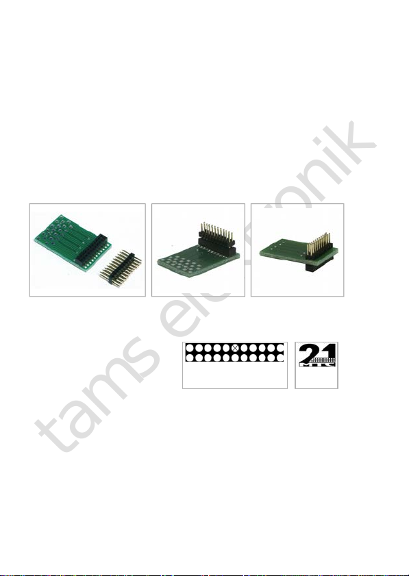
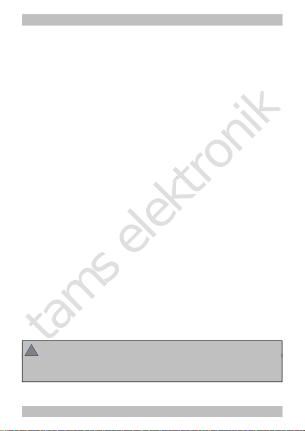
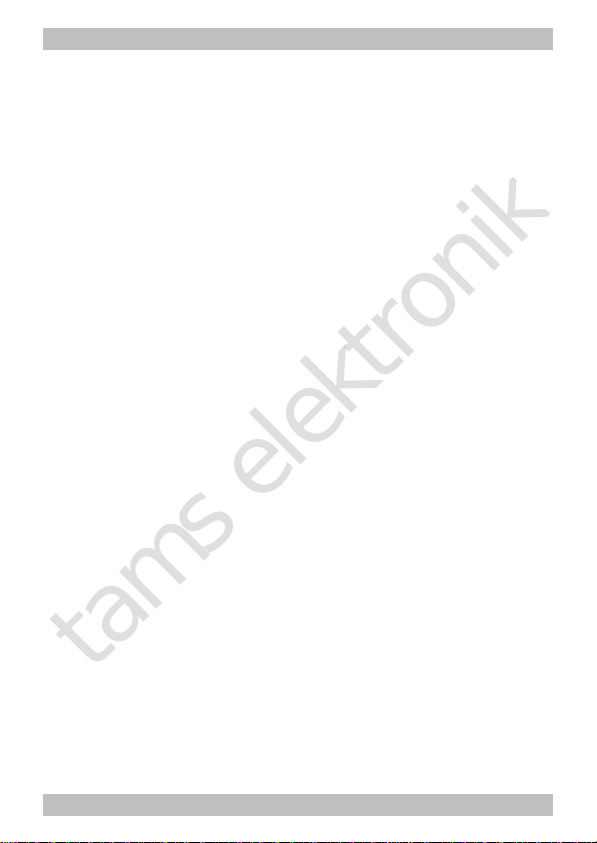
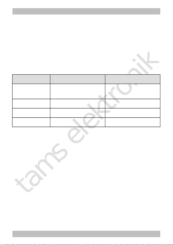
Adapter for PluX- and 21MTC-Interface Engl sh
In schools, tra n ng centres, clubs and workshops, assembly must be
superv sed by qual f ed personnel.
In ndustr al nst tut ons, health and safety regulat ons apply ng to
electron c work must be adhered to.
3. Safe and correct solder ng
Caution:
Incorrect solder ng can cause dangers through f res and heat. Avo d
these dangers by read ng and follow ng the d rect ons g ven n the
chapter Safety instructions.
Use a small solder ng ron w th max. 30 Watt or a regulated
solder ng ron.
Only use electron c t n solder w th flux.
When solder ng electron c c rcu ts never use solder ng-water or
solder ng grease. They conta n ac ds that can corrode components
and copper tracks.
Insert the component connect ng p ns nto the PCB´s holes as far as
poss ble w thout force. The components should be close to the
PCB`s surface.
Observe correct polar ty or entat on of the parts before solder ng.
Solder qu ckly: hold ng the ron on the jo nts longer than necessary
can destroy components and can damage copper tracks or solder ng
eyes.
Apply the solder ng t p to the solder ng spot n such a way that the
part and the solder ng eye are heated at the same t me.
S multaneously add solder (not too much). As soon as the solder
becomes l qu d take t away. Hold the solder ng t p at the spot for a
few seconds so that the solder flows nto the jo nt, then remove the
solder ng ron.
Page 7