TAMURA TU-6440 User manual

2D-53-0002660C
本機の廃棄について
本器を廃棄する場合は、産業廃棄物の扱いとなりますので、産業廃棄物処分
業の許可を取得している会社に処分を委託して下さい。
取扱説明書
GPIO CARD
型番:TU-6440
この取扱説明書には、事故を防ぐための重要な注意事項と製品の取り扱いかたを示
しています。この「取扱説明書」をよくお読みのうえ製品を安全にお使いください。お読み
になったあとは、いつでも見られるところに必ず保管してください。

2D-53-0002660C
安全上のご注意
ここでは、本製品を安全にご使用頂く上で大切な「禁止事項」「注意事項」につ
いて記載しています。御使用の前に必ずお読み頂き、正しくご使用頂くようお願い
致します。
注意
「人が障害を負ったり、物的損害の発生が想定される」内
容を示します。
△記号は注意しなければならない内容(警告を含む)を示していま
す。具体的な注意内容は△の中や近くに絵や文章で示しています。
記号は、禁止内容(してはならないこと)を示しています。具体的な
禁止内容は の中や近くに絵や文章で示しています。
注意
本製品を静電気の影響を受けやすいところ(絨毯の上など)に放置しないでくだ
さい。故障の原因となる事があります。
電源スイッチを入れたまま、本製品を抜き差ししないでください。故障の原因と
なる事があります。

2D-53-0002660C
商品概要
汎用制御信号を入出力するインターフェースカードです。
装着方法について
カードの装着方法については、装着する機器の取扱説明書も参照ください。必ず本
機を装着した機器の電源コードを抜いた状態で取り付け・取り外しを行ってください。カ
ードの左右にある取り付けネジは、しっかり締めた状態でご使用ください。
ネジの取り付けが緩い場合、電気的信号レベルが安定せず、正しい状態でお使いい
ただけません。

2D-53-0002660C
製品構成
品目コード
型式
名称
数量
備考
M-21300273-00
TU-6440
GPIO CARD
1
取り付け用ネジ
2
M3x8
取扱説明書
1
本書
仕様
汎用制御信号入力
(GPI INPUT)
16ch フォトカプラ絶縁入力
37pin D-type コネクタ(オス)
汎用制御信号出力
(GPI OUTPUT)
16ch オープンコレクタ出力
37pin D-type コネクタ(メス)
外観寸法
129(W)×40(H)×152(D)mm
質量
168g
各部の説明
①.GPI 入力コネクタ
汎用制御信号入力用コネクタです。
②.GPI 出力コネクタ
汎用制御信号出力用コネクタです。
①
②

2D-53-0002660C
コネクタピンリスト
GPI INPUT
コネクタ:DCLC-J37PAF-10L9E ロックネジ 2.6mm
Pin No.
Signal
Pin No.
Signal
1
+COM1
20
+COM4
2
IN1-1
21
IN4-1
3
IN1-2
22
IN4-2
4
IN1-3
23
IN4-3
5
IN1-4
24
IN4-4
6
GND
25
GND
7
+COM2
26
NC
8
IN2-1
27
NC
9
IN2-2
28
NC
10
IN2-3
29
NC
11
IN2-4
30
NC
12
GND
31
GND
13
+COM3
32
NC
14
IN3-1
33
NC
15
IN3-2
34
NC
16
IN3-3
35
NC
17
IN3-4
36
NC
18
GND
37
GND
19
NC
GPI OUTPUT
コネクタ:DCLC-J37SAF-10L9E ロックネジ 2.6mm
Pin No.
Signal
Pin No.
Signal
1
OUT1
20
OUT9
2
COM1
21
COM9
3
OUT2
22
OUT10
4
COM2
23
COM10
5
OUT3
24
OUT11
6
COM3
25
COM11
7
OUT4
26
OUT12
8
COM4
27
COM12
9
OUT5
28
OUT13
10
COM5
29
COM13
11
OUT6
30
OUT14
12
COM6
31
COM14
13
OUT7
32
OUT15
14
COM7
33
COM15
15
OUT8
34
OUT16
16
COM8
35
COM16
17
+5V
36
GND
18
+5V
37
GND
19
NC

2D-53-0002660C
入出力ピンの定格
GPI INPUT
GPI INPUT の+COM 端子は下図に示す電圧の範囲内で使用して下さい。
IN 端子は下図に示す電流が流れます。
GPI OUTPUT
GPI OUTPUT は下図に示す電圧、電流の範囲内で使用して下さい。
MAX 30V
MAX 20mA
OUT
COM
+4V~+25V
IN
MAX5mA
GND
+COM

2D-53-0002660C
寸法図

2D-53-0002660C
カスタマーサービスについて
ご使用中に不具合が発生し修理を必要とする場合、また動作運用上についてご
不審の点、その他弊社取扱品目についてご不明の点、あるいはご用命事項がございま
したら下記あてご連絡下さい。
(なお、修理・再調整の期間短縮のために、故障時前後のご使用状況・経歴等を
詳細にお知らせ下さい。)
本社/〒178-8511 東京都練馬区東大泉 1-19-43
TEL(03)3978-2111 FAX(03)3923-0230
お問合せ先
ブロードコム事業部 営業部/本社内
TEL(03)3978-2146 FAX(03)3978-2005
西日本営業所/〒564-0062 大阪府吹田市垂水町 3-27-27
第2江坂三昌ビル
TEL(06)4861-7722 FAX(06)4861-7728

2D-53-0002660C
Disposing of this Equipment
When disposing this equipment, contact an authorized industrial waste
disposal operator to handle the disposal since this equipment needs to be
disposed as an industrial waste.
Instruction Manual
GPIO CARD
Model Number:TU-6440
This Instruction Manual describes important precautions to prevent any
accident and procedures to handle this product.Read this Instruction Manual
carefully to use this product safely.
After reading, keep this in a safe place where users can refer to as
needed.

2D-53-0002660C
Safety Precautions
This section describes the "prohibitions" and "precautions" important for
you to use this product safely.
Before use, be sure to read this manual so that you can use the system
correctly.
Caution
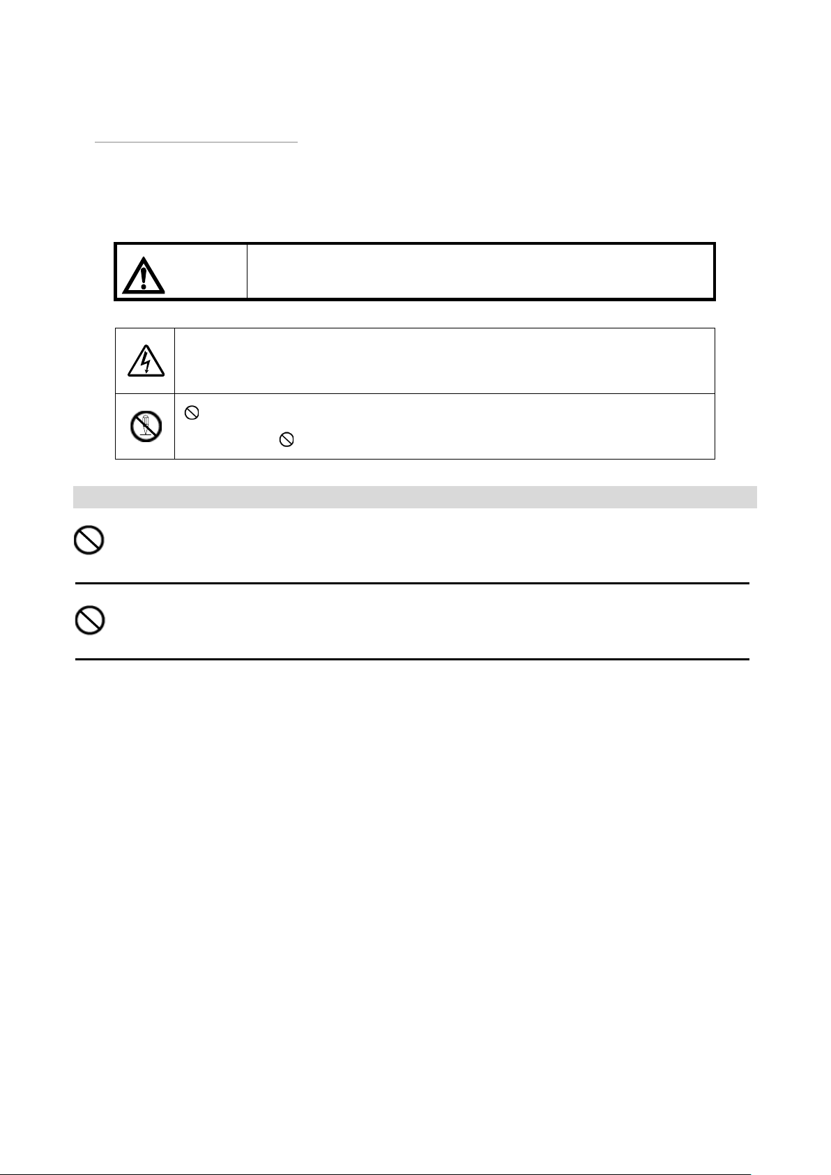
This sign gives a message assuming possible
human injury or property damage if the system
is mishandled ignoring the message given with
this sign.
The △symbol shows a message (including a warning) that
must be paid attention to. The specific precaution is shown
by picture or text near or in the △.
The symbol shows a prohibition (prohibited action). The
specific prohibition is shown by picture or text near or in the
.
Caution
Do not put this product in places where it is susceptible to static
electricity (such as on a carpet). This may cause system malfunctions.
Do not connect/disconnect this product with the power switch on. This
may cause system malfunctions.

2D-53-0002660C
Overview
This card is control interface card that input and output general-purpose
control signals
About How to install
Please see the instruction manual for installation on the installation
method of the card. Installing or removing make sure unplugged the device
must be equipped with this unit. Use securely fastened with screws on either
side of the card.
If the mounting of the screw is loose, you do not can use it in the correct
state. Because the electrical signal level is not stable.

2D-53-0002660C
Included items
Product code
Model
Name
Quantity
Remarks
M-21300273-00
TU-6440
GPIO CARD
1
Mounting
screw
2
M3x8
Instruction
Manual
1
This Book
Specifications
General-purpose control signal
inputs(GPI INPUT)
16ch electrically isolated
opto-coupler inputs
37-pin D-type connector(male)
General-purpose control signal
outputs(GPI OUTPUT)
16ch open-collector outputs
37-pin D-type connector(female)
Dimensions
129(W)×40(H)×152(D)mm
Weight
168g
Description of parts
①.GPI INPUT Connector
This is the connector for general-purpose control signal inputs.
②.GPI OUTPUT Connector
This is the connector for general-purpose control signal outputs.
①
②

2D-53-0002660C
Connector Pin List
GPI INPUT
Connector:DCLC-J37PAF-10L9E Locking screw 2.6mm
Pin No.
Signal
Pin No.
Signal
1
+COM1
20
+COM4
2
IN1-1
21
IN4-1
3
IN1-2
22
IN4-2
4
IN1-3
23
IN4-3
5
IN1-4
24
IN4-4
6
GND
25
GND
7
+COM2
26
NC
8
IN2-1
27
NC
9
IN2-2
28
NC
10
IN2-3
29
NC
11
IN2-4
30
NC
12
GND
31
GND
13
+COM3
32
NC
14
IN3-1
33
NC
15
IN3-2
34
NC
16
IN3-3
35
NC
17
IN3-4
36
NC
18
GND
37
GND
19
NC
GPI OUTPUT
Connector : DCLC-J37SAF-10L9E Locking screw2.6mm
Pin No.
Signal
Pin No.
Signal
1
OUT1
20
OUT9
2
COM1
21
COM9
3
OUT2
22
OUT10
4
COM2
23
COM10
5
OUT3
24
OUT11
6
COM3
25
COM11
7
OUT4
26
OUT12
8
COM4
27
COM12
9
OUT5
28
OUT13
10
COM5
29
COM13
11
OUT6
30
OUT14
12
COM6
31
COM14
13
OUT7
32
OUT15
14
COM7
33
COM15
15
OUT8
34
OUT16
16
COM8
35
COM16
17
+5V
36
GND
18
+5V
37
GND
19
NC

2D-53-0002660C
Rated Input / Output Pins
GPI INPUT
+COM terminal of GPI INPUT should be used within the range of voltage
shown below.
The current shown in the figure below flows at IN terminal.
GPI OUTPUT
GPI OUTPUT should be used within the range of voltage and current
shown below.
MAX 30V
MAX 20mA
OUT
COM
+4V~+25V
IN
MAX5mA
GND
+COM

2D-53-0002660C
Dimensions

2D-53-0002660C
About Customer Service
If you experience any problems with our products and require any
servicing, or have any questions about TAMURA product line, please contact
your TAMURA sales representative or TAMURA at the following locations.
To help speed up servicing and readjustment, please be ready to describe
the problem accurately, what operations you were performing before and
after it happened, or the history of usage.
(Head Office)
1-19-43, Higashi-Oizumi, Nerima-ku, Tokyo, 178-8511 Japan
Phone : +81-3-3978-2111 Fax : +81-3-3978-0230
(Contact)
International Sales Broadcom Business Unit
Phone : +81-3-3978-2242 Fax : +81-3-3978-2005
Table of contents
Other TAMURA Recording Equipment manuals
Popular Recording Equipment manuals by other brands

SCHNERZINGER
SCHNERZINGER GIGA PROTECTOR quick start guide

Greenlee
Greenlee 77M-G instruction manual

IntesisHome
IntesisHome LG-RC-WIFI-1 installation guide

Xaoc Devices
Xaoc Devices KAMIENIEC Operator's manual

DX Engineering
DX Engineering DXE-TVSU-1B manual

MFJ
MFJ signal enhancer II mfj-752d instruction manual