Tanda TX7331 User manual

TX7331
Intelligent Graphic Repeater Panel
Installation and Operation Manual
TANDA UK Technology Copyright ©2015, All right reserved.

TX7331 Intelligent Graphic Repeater Panel
Installation & Operation Manual
4050100365-Rev1.1-1117
TANDA UK
Specifications are subject to change without prior notice
2
Product Safety
To prevent severe injury and loss of life or property, read the instruction carefully before installing the
Intelligent Graphic Repeater Panel to ensure proper and safe operation of the system.
European Union directive
2012/19/EU (WEEE directive): Products marked with this symbol cannot be disposed
of as unsorted municipal waste in the European Union. For proper recycling, return
this product to your local supplier upon the purchase of equivalent new
equipment, or dispose of it at designated collection points.
For more information please visit the website at www.recyclethis.info

TX7331 Intelligent Graphic Repeater Panel
Installation & Operation Manual
4050100365-Rev1.1-1117
TANDA UK
Specifications are subject to change without prior notice
3
Table of Content
1 Introduction .................................................................................................................................................. 4
1.1 General ................................................................................................................................................... 4
1.2 Features and Benefits ......................................................................................................................... 4
1.3 Technical Specifications .................................................................................................................... 4
2 Installation ..................................................................................................................................................... 5
2.1 Installation Preparation ...................................................................................................................... 5
2.2 Installation and Wiring ........................................................................................................................ 5
3 Operation ...................................................................................................................................................... 9
3.1 Preparation ............................................................................................................................................ 9
3.2 Repeater Addressing .......................................................................................................................... 9
3.3 LED Panel Operations ...................................................................................................................... 10
4 General Maintenance ............................................................................................................................ 11
5 Troubleshooting ......................................................................................................................................... 11
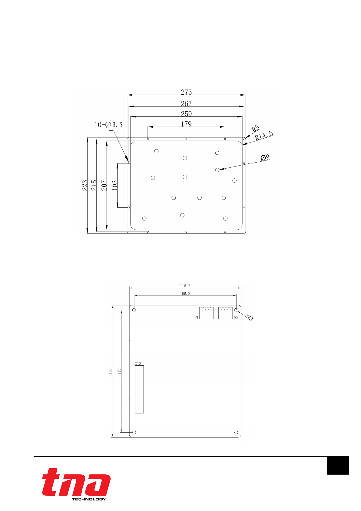
Appendix 1 ..................................................................................................................................................... 11
Installation of the Main Board ............................................................................................................... 11
Appendix 2 ..................................................................................................................................................... 11
Limitation of the LED Board ................................................................................................................... 11
Appendix 3 ..................................................................................................................................................... 12
Limitation of the Key Board ................................................................................................................... 12
Appendix 4 ..................................................................................................................................................... 12
Limitation of the Buzzer ........................................................................................................................... 12
Appendix 5 ..................................................................................................................................................... 12
Limitation of the LED ................................................................................................................................ 12
Appendix6 ...................................................................................................................................................... 13
Configuration of the Whole ................................................................................................................... 13
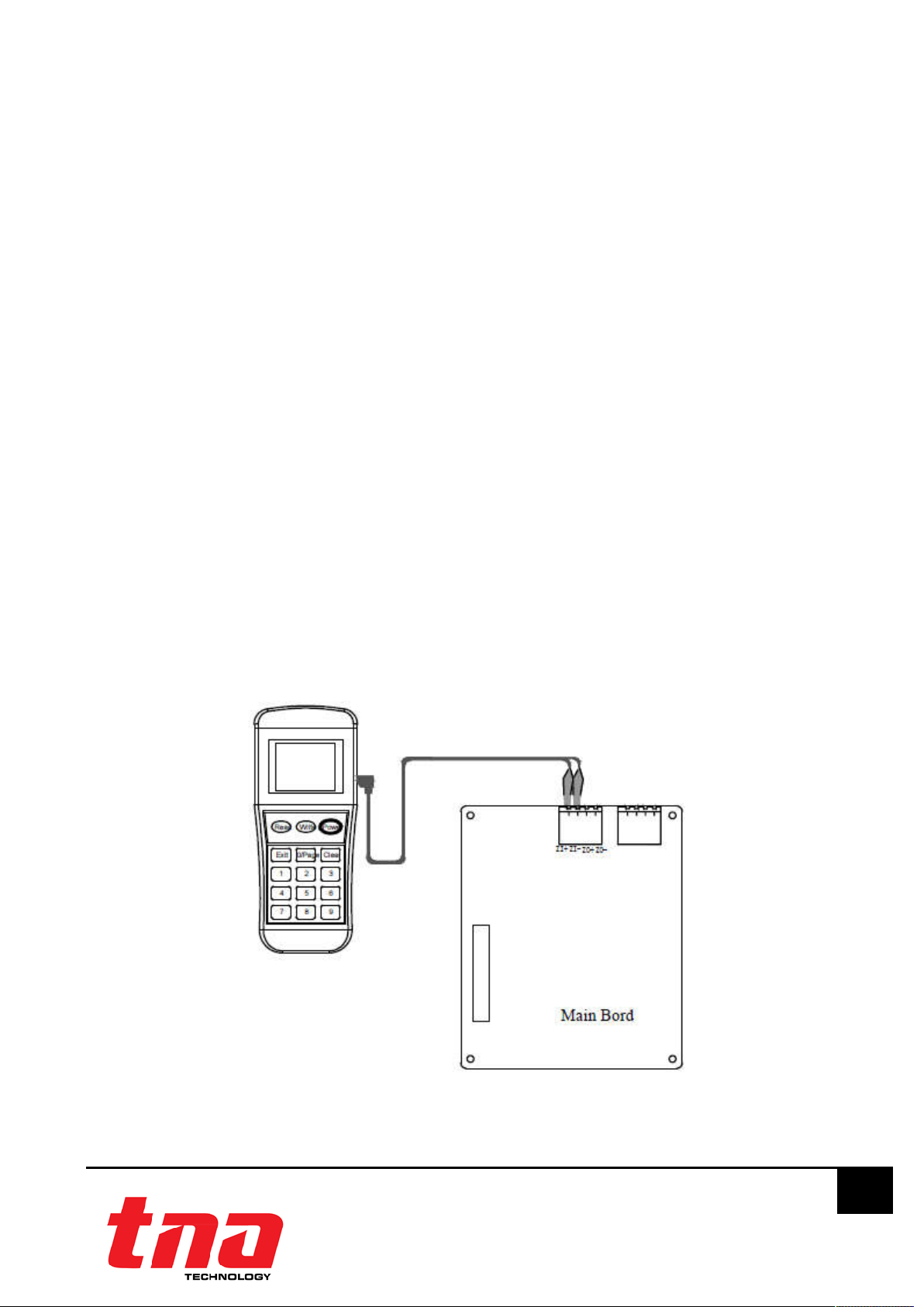
Appendix7 ...................................................................................................................................................... 14
Connection of Repeater Panel ............................................................................................................ 14
Appendix 8 ..................................................................................................................................................... 15
Limitation of Interface Module ............................................................................................................. 15

TX7331 Intelligent Graphic Repeater Panel
Installation & Operation Manual
4050100365-Rev1.1-1117
TANDA UK
Specifications are subject to change without prior notice
4
1 Introduction
1.1 General
TX7331 Intelligent Graphic Repeater Panel is designed with built-in MCU processor and it can fast
relay response with simultaneous audible and visual signal output. This repeater panel can also
program to limit the zone display from All Zones into a particular zone or device. Also it can supervise
and indicate the groups as well as device. The unit is connected through the communication loop
of TX7004 Intelligent control panel along with the devices and can install up to 254 units per loop. The
repeater panel can be used whenever there is a need to relay information to multipoint informing
key personnel.
The unit is manufactured base on the requirement of EN 54 part 2, European Standard. The unit is
compact size and aesthetically pleasing with unobtrusive design that will complement modern
building designs. The unit is compatible to the TX7004 Analogue Intelligent Fire Alarm Control Panel,
produced by single manufacture T&A, to avoid addressable communication compatibility problem.
1.2 Features and Benefits
EN54-2 Compliance
Fire display passive repeater panel
Built-in MCU processor and digital addressing
Fast response of audible and visible signal from the panel
Programmable Zone Display a particular zone or device . and indicate the groups or device
Supervise information
LED status indicator
Onsite Adjustable Parameter
Loop sited wiring with external 24V supply
Compact size and aesthetically pleasing design
1.3 Technical Specifications
Compliance EN 54-2: 1997+A1: 2006
Input Voltage Loop Power: 24VDC [16V to 28V]
External PSU: 24VDC [20 to 28V]
Current Consumption Loop: Standby: 1mA, Alarm: 1.2mA
External PSU: Standby: 25mA, Alarm: 80mA
Memory Capacity Up to 256 fire event history
Number per loop Up to 256 units (ideal)
Material / Colour Flat sheet Metal / black
Dimension / LWH 394mm x 274mm x63mm(Can according to user
requirements,the dimension should be amended
accordingly)
Operating Temperature 0°C to +40°C
Humidity 0 to 95% Relative Humidity, Non condensing

TX7331 Intelligent Graphic Repeater Panel
Installation & Operation Manual
4050100365-Rev1.1-1117
TANDA UK
Specifications are subject to change without prior notice
5
2 Installation
2.1 Installation Preparation
This Intelligent Graphic Repeater Panel must be installed, commissioned and maintained by a
qualified or factory trained service personnel. The installation must be installed in compliance with all
local codes having a jurisdiction in your area or BS 5839 Part 1 and EN54.
Warning: The electronic components inside the panel are vulnerable to damage by electrostatic
discharges. It is recommended to wear a wrist strap designed to prevent the build-up of static
charges within the body, before handling any electronic circuit board.
2.2 Installation and Wiring
1.Appearance of the repeater panel is shown in Fig. 1.
(1)LED Indicators
Aside from the LED Board´s Indicator, the TX7331 LED indicator indicate the working status of the unit
as refers to the below table.
LED Indicator Colour Description
On
Green When illuminated it indicates the power supply is present
Fire Red When illuminated it indicates that a FIRE or Supervise information
has been detected in the protected location
Mute Green When illuminated it indicates that the MUte button has been
pressed
Communication
Green When illuminated it indicates that the repeater panel is online
communication with the control panel
Figure 1

TX7331 Intelligent Graphic Repeater Panel
Installation & Operation Manual
4050100365-Rev1.1-1117
TANDA UK
Specifications are subject to change without prior notice
6
(2)Description of Keys
MUTE: This button mutes the buzzer of the repeater panel. Pressing the mute button will stop the
internal panel buzzer.
Self-test: In standby state, pressing this key the repeater panel will start self-test.
2. The front panel is shown in Fig. 2.
3.Mounting of the Main board
Installation method is shown in Fig.3. See Appendix 1 and 6 for more information.
Figure 2
Figure 3

TX7331 Intelligent Graphic Repeater Panel
Installation & Operation Manual
4050100365-Rev1.1-1117
TANDA UK
Specifications are subject to change without prior notice
7
4.Mounting of the LED Board
Installation method is shown in Fig.4. See Appendix 2 and 6 for more information.
5.Mounting of the Key Board
Installation method is shown in Fig.5. See Appendix 3 and 6 for more information.
Figure 4
Figure 5

TX7331 Intelligent Graphic Repeater Panel
Installation & Operation Manual
4050100365-Rev1.1-1117
TANDA UK
Specifications are subject to change without prior notice
8
6.Mounting of the Buzzer
Installation method is shown in Fig.6. See Appendix 4 and 6 for more information.
7.Mounting of the LED
Installation method is shown in Fig.7. See Appendix 5and 6 for more information.
8.Terminals
Terminals are shown in Fig.8.
ZI+, ZI-, ZO+, ZO-: The communication cable terminals connecting with the fire alarm control panel.
Figure 6
Figure 7
Figure 8

TX7331 Intelligent Graphic Repeater Panel
Installation & Operation Manual
4050100365-Rev1.1-1117
TANDA UK
Specifications are subject to change without prior notice
9
DI+, DI-, DO+, DO-: 24DC power supply wiring terminal, non polarized.
3 Operation
3.1 Preparation
The TX7930 handheld programmer is used to configure Intelligent Graphic Repeater Panel soft
address. This tool is not included, must be purchased separately. The programmer is packed with
twin 1.5V AA battery and cable, ready for usage once received.
It is mandatory for the commissioning personnel to have programmer tool in order to adjust the
Intelligent Graphic Repeater Panel conferring to the site situation and environmental requirements.
Program a unique address number for each device according to the project layout before placing
from the Terminal Base.
Warning: Disconnect the loop connection whilst connecting to the handheld programmer.
3.2 Repeater Addressing
1. Connect the programming cable to ZI+ and ZI- (or ZO+ and ZO-) terminals (Figure 9). Press
“Power” to switch on the unit.
2. Switch-on the programmer, then press button “Write” or number “2” to enter Write Address
mode (Figure 10).
3. Input the desire device address value from 1 to 254, and then press “Write” to save the new
address (Figure 11).
Note: If display “Success”, means the entered address is confirmed. If display “Fail”, means failure to
program the address (Figure 12).
4. Press “Exit” key to go back Main Menu. Press “Power” key to switch-off the programmer.
Figure 9: Programmer Connection Detail

TX7331 Intelligent Graphic Repeater Panel
Installation & Operation Manual
4050100365-Rev1.1-1117
TANDA UK
Specifications are subject to change without prior notice
10
3.3 LED Panel Operations
Set up the system according to the project requirement.
As shown in the figure of the Repeater Panel , Adjust the the dip switch install to configurate the
required pattern. The figure in the lower right of the Repeater Panel´s Main board as shown below:
Configuration mode:
Programmable Zone Display a particular zone or device ,and indicate the groups or device
Supervise information.
(1) Configuration Preparation
According to the figure 13 configuration. Switched on the 24VDC power to the Repeater
Panel´s Main board and the USB connect with computer.
(2) Configuration and Download
Download the pre-configured data base from TX7810 programming software through a
computer to the control panel. Refer to the TX7810 Defining Tool manual for more details.
NormalWork mode:
In the configuration model is complete, please according to the figure 13 configurate the DIP switch
to normalWork mode, The model for the normal work of Graphic Repeater Panel.
1. Read
2. Write T
3. R/W Config 7
4. Set
Figure 10
Address: 001
Next Address: 002
Success
Address: 001
Fail
Figure 11 Figure 12
Figure 13: DIP Switch (SW1) connect
explanation

TX7331 Intelligent Graphic Repeater Panel
Installation & Operation Manual
4050100365-Rev1.1-1117
TANDA UK
Specifications are subject to change without prior notice
11
4 General Maintenance
1. Inform the suitable personnel before conducting the maintenance.
2. Disable the Intelligent Graphic Repeater Panel on the control panel to prevent false alarm.
3. Do not attempt to repair the circuitry of the Intelligent Graphic Repeater Panel, it may affect
the operation to respond to a fire condition and will void the manufacturer’s warranty.
4. Notify again proper personnel after conducting the maintenance and make sure to enable
the Intelligent Graphic Repeater Panel and confirm if up and running.
5. Perform the maintenance on semi-annually or depending on the site conditions.
5 Troubleshooting
What you notice What it means What to do
Address not enrolling The wiring is loose
The address is duplicate
Conduct maintenance
Re-Commission the device
Unable to commission The damage the electronic circuit Replace the device
Appendix 1
Installation of the Main Board
As shown in the figure below is Main Board with Box weld nut Connection.
Appendix 2
Limitation of the LED Board
As shown in the figure below is LED Board with front panel weld nut Connection.

TX7331 Intelligent Graphic Repeater Panel
Installation & Operation Manual
4050100365-Rev1.1-1117
TANDA UK
Specifications are subject to change without prior notice
12
Appendix 3
Limitation of the Key Board
As shown in the figure below is Key Board with the door weld nut Connection.
Appendix 4
Limitation of the Buzzer
As shown in the figure below is Buzzer with the door weld nut Connection.
Appendix 5
Limitation of the LED
1. Light emitting diode

TX7331 Intelligent Graphic Repeater Panel
Installation & Operation Manual
4050100365-Rev1.1-1117
TANDA UK
Specifications are subject to change without prior notice
13
2. Nylon sleeve of light emitting diode
3. front panel
Assembly steps:
Please put lights in accordance with the directions in the hole
According with the B indicate directions, will the Light emitting diode put in the front panel ofΦ9
Through-hole.
Appendix6
Configuration of the Whole
NOTE:

TX7331 Intelligent Graphic Repeater Panel
Installation & Operation Manual
4050100365-Rev1.1-1117
TANDA UK
Specifications are subject to change without prior notice
14
1 LED Board
2 Lock
3 Buzzer
4 front panel
5 Key Board
6 Box
7 Main Board
Appendix7
Connection of Repeater Panel
Name Cable No. Model and Size Length Remarks
Ribbon Cable
X01 Flat Cable 34P
360mm Connecting XT3
on Main Board
and XS1on LED
board
Ribbon Cable
X02 Flat Cable 10P
320mm Connecting XT1
on Main Board
and XS1on Key
board
Buzzer Cable
X03 UL1007 AWG26
130mm Connecting XS2
on Key board and
Buzzer
Lamp Cable
XN UL1007 AWG26
500mm Connecting HL1-
HL256 on LED
board and LED
Indicators

TX7331 Intelligent Graphic Repeater Panel
Installation & Operation Manual
4050100365-Rev1.1-1117
TANDA UK
Specifications are subject to change without prior notice
15
Appendix 8
Limitation of Interface Module
The Intelligent Graphic Repeater Panel cannot last forever. In order to keep the Intelligent Graphic
Repeater Panel working in good condition, please maintain the equipment continuously according
to recommendations from manufacturers and relative nation codes and laws. Take specific
maintenance measures on the basis of different environments.
These Intelligent Graphic Repeater Panel contain electronic parts. Even though it is made to last for
a long period of time, any of these parts could fail at any time. Therefore, test your repeater at least
every half-year according to national codes or laws. Any Intelligent Graphic Repeater Panel, fire
alarm devices or any other components of the system must be repaired and/or replaced
immediately as they fail.
Table of contents