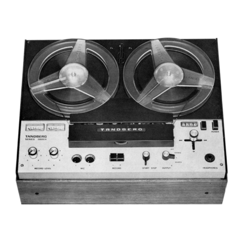
TANDBERG 3000 X series User manual

TANDBERG
Series SOOOX
SERVICE MANUAL
;
ir--I
t ";' ll "--: I
TANDAERG
oc
reCOAO LEEL
ryr;
A
*q r
ruc
"t
-
;TANDBERGS RADIOFABRIKK A/S

-
-
A
^a

.G.
Contents
F
1.0TECHNICALSPECIFICATIONS
2.0 MECHANCIALADJUSTMENTS
2.1Clutches .....:.
2.1.1Take-up
Turntable
2.1.2 Take-up Turntable
2.1.3Supply
Turntable
2.1.4Supply
Turntable
2.2 Brakes
2.3 Pressure Pad Adiustment . .
2.4 End Stop Mechanism .
2.4.1Tape FeelerTension
2.4.2Adjustmentof Tape Feeler
3.0ALIGNMENT .
3.1 Demagnetlzing
3.2 Blas- and Erase Circuits
3.2.1
Oscillator Frequency ...
3.2.2 Erase Voltage
3.2.3Bias Current
4.0 TAPE PATH
4.1 Visual Check
4.2 Mechanlcal adjustment ol tape path . . .
5.0 HEADALIGNMENTWITH TANDBERGTEST
TAPES,MODEL3041X
5.1 Playback head
5.1.1HeightAdjustment
5.1.2Azimuth Adjustment
5.2 Record Head .
5.2.1HeightAdlustmentby Visual
Inspection
5.2.2Height Adjustment by Track
Measurement. ....
5.2.3.AzimuthAdjustment...
5.3 Bias Head
5.3.1Vertical Adjustment ....
5.3.2HeightAdjustment
5.3.3Horizontal Adjustment
5.4 Erase Head .
5.4.1HeightAdjustment
5.4.2Azimuth Adjustment
5.5 Model 3021X .
6.0 HEADALIGNMENTWITHOUTTANDBERG
TEST TAPES,MODEL 3041X
6.1 Playback Head .
6.1.1
HeightAlignment
6.1.2Azimuth Alignment . ...
6.2 Record Head .
6.3 Bias Head
6.4 Erase Head .
6.4.1Height Adjustment
6.4.2Azimuth Adjustment
6.5 Model 3021X .
7.0 TRACK CONTROL
7.1 Model 3041X .
7.1.1
Record Head
7.1.2
Erase Head .
7.1.3
PlaybackHead
7.2 Modell 3021X .
7.2.1Erase Head .
7.2.2Record Head
7.2.3 Playback Head
8.0ADJUSTMENT
AND CONTROL
OF
THE AMPLIFIERS ... 11
8.1.1PlaybackLevel
Adjustment...... 11
8.1.2Adjustment
of Bias
Current...... 11
8.1.3Record/PlaybackLevel Adiustment11
8.1.4Record/Playback
Curves ... ..... 11
8.1.5Distortion ........ 11
8.1.6
Control
of Playback
Amplifier.... 1'l
8.2
Tape Speed Control .... 12
8.2.1Using FrequencyMeter
or Counter12
8.2.2Using Transformer and Vacuum
Tube Voltmeter .. ...... . 12
8.2.3UsingTapeof Known Length .... 12
9.0 RECORD/PLAYBACK
CURVES ..... 12
9.1 Readjustment ol Record/Playback Level 12
9.2Dlstortlon.... .........12
9.3 Control of Playback and Record
Ampliliers .... ... 12
9.3.1PlaybackAmplifier .... ... 12
9.3.2Record Amplifier ......... 13
10.0MoDrFtcATroNS ... 15
10.1 Modilications from 11511301230/240
V,
50/60 Hz Operation . .. . 15
10.2 Modification lrom Four-Track to Two-
TrackVersion... ......15
10.3 ComponentModificationin Series3000X15
11.LUBRTCATTON. ...... 15
12.0ILLUSTRATIONSWITH REFERENCE
PARTNUMBERS.. ..... 16
13.0
SPARE
PARTSLIST FOR MODEL3OOOX.. 22
13.1MechanicalParts ... ... 22
13.2Electrica!Components.. .... . 26
14.0TABLE OF TRANSISTORSUSEDIN
MODEL 3OOOX
15.0BLOCKDIAGRAMFORMODELSOOOX
.... 28
16.0PRINTEDWIRINGBOARDSAND WIRING
DIAGRAM
16.1European Version
16.2U.S.
Version
10
10
'10
10
11
11
11
11
11
4
4
4
4
4
4
5
6
6
6
6
7
7
7
7
7
7
8
8
8
I
I
9
9
9
9
9
I
9
9
9
9
I
I
10
10
10
10
10
10
10
10
10
10
10
10 28
30

1.0TECHNICALSPECIFICATIONS
POWERREQUIREMENTS: 115-130-230-240 V. 50 or 60 Hz operation.See chapter 10.1 for voltage
connections.
POWER CONSUMPTION: 45 watts.
MOTOR: Asynchronous.
TAPE SPEED: 17leips,
33/r
ips and 7tlzips.
TAPE: Maximumreel diameter7". Low NoiseTape only should be used for recordinq
and for adjustment
procedure.
WINDING
TIMES: 1200ft. of tape; 131min.
1800ft. of tape: 2t/z min.
PLAYINGTIME, Two track recordingon 1800ft. of tape.
MODEL3021X: Stereo Mono
7t/z ips: 48 min. 2 x 48 min.
33/,r
ips: 96 min. 2 x 96 min.
17laips: 192min. 2 X 192min.
PLAYINGTIME, Fourtrack recordingon 1800
ft. of tape.
MODEL3041X: Stereo Mono
71/zips: 2 x 48 min. 4 x 48 min.
33/rips: 2 x 96 min. 4 x 96 min.
17leips: 2 x 192min. 4 x 192min.
SPEEDTOLERANCE: -+ 1,50/0.
HEADS: Separateheads
for erasure,recording,
playback
and bias(Tandberg
Cross-field).
FREQUENCYRESPONSE: 7t/z ips: 40-20.000Hz -+ 2dB
33/r
ips: 50-16.000Hz -+-
2dB
17e ips: 50- 9.000Hz -+ 2dB
Measuredto DIN 45511:
7t/z ips: 4O-22.0O0
Hz
33/rips: 40-18.000Hz
17laips: 40-10.000Hz
Amplifier
position:
50-18.000 Hz -+ 3 dB
ERASEAND BIAS 85,5 kHz. Distortionless than 0,5%.
FREQUENCY:
INDICATORS: Movingcoil meters.Optimum recording level: Deflectionup to 0 dB at maxi-
mum3o/o
distortion.
AMPLIFIERDISTORTION: RecordAmplifier:Recordingof a 400 Hz signat at 0 dB level,
gives less than
0,5
0/o
distortion
from recording
amplifier.
PlaybackAmplifier:0,3
0/o
distortion
at 0, 75 V output voltage.
TAPE DISTORTION: A tape recordedwith a 40OHz signal at 0 dB level,
gives less than 30/otape
distortion
in playback.
A tape recordedwith a 400 Hz signal8 dB below 0 dB on indicator,
gives less
than 0,8
0/o
tape distortionin playback.
Wl
cl
A
C
!(
fi (
i

-
a
WOW: W.
R.M.S.:
7t/z ips - better than 0,07
o/o
33/rips - better than 0,140/o
17le
ips - better than 0,280/o
DtN 45511:
71/z
ips - better than 0,1
o/o
33/r ips - better lhan O,2o/o
17le
ips - better than 0,40lo
CROSSTALK At 1OOO
Hz:
ATTENUATION: Mono ) 60 dB Stereo ) SOOA
INPUTS: Each channelhas the following inputs:
1. Microphone input for dynamic low impedance microphone. lmpedance:
200-700 ohm. Sensitivity
at 400 Hz: 0,1 mV. Maximum input level: 25 mV.
DINsocket.
US-version,
Telephone
jack.
2. Line input for high impedancesource. lmpedance: 1 Mohm. Sensitivityat
400 Hz: 100mV. Maximum input level:20 V. Phono sockets,LINE lNpUTS.
3. Line input for low impedancesource. lmpedance:
57 kohm. Sensitivity
at
400 Hz: 5 mV. Maxirnuminput level: 1 V. DIN socket RADIO: Pin 1, left
channel:Pin 4, right channel.
US-version:
Phono sockets LOW lN.
OUTPUTS: Emitterfollower outputs,RADIO DIN socket pins 3 and 5. US-version:
phono
SocKetS,
OUTPUT
LEFT and RIGHT.
Minimumload impedance:
100ohm. Output level:
A tape recordedwith 400 Hz
signal at 0 dB level,
gives approx.0,75V in playback.HEADPHONES,
stereo
jack for connection
of headphones.
Stereojack is connected in parallelwith RADIOsocket pins 3 and 5. On US-
version stereo jack is connected parallel with phono sockets OUTPUT LEFT
and RIGHT.
SfGNALTAPE/NOISE Peak value measured
according to DIN 45511
at tape speed 71/zips and 5olo
WEIGHTED tape distortion:
(GERAUSCHSPANNUNG): 4-track 2-track
54 dB 56 dB
SIGNALTAPE/NOISE Peak value measured
accordingto DIN 45511
at tape speed 7t/z ips and 5o/o
UNWEIGHTED distortion:
(FREMDSPANNUNG): 4-track 2-track
51 dB 51 dB
SIGNAL/TAPE
NOISE: Measuredlinear R.M.S.
at tape speed 7'lz ips and 5o/o
distortion:
4-track 2-track
57 dB s7 dB
SfGNAL/TAPE
NOISE: Measuredat tape speed
7t/zips and 50/o
distortion:
Wetonreo 4-track z-track
(lEC A-CURVE)
R.M.
S.: 62 dB 64 dB
Note: At 30/o
distortion all signal to noise ratio measurements(Signal/tape
noise)
are reducedby 2 dB.
DfMENSIONS: Length: 151/2"
(39,4
cm), heigth: 6t/2" (16,5cm) and depth: 123la"
(31,6cm).
WEIGHT: 20lbs(9,1
kg).

2.0MECHANICAL
ADJUSTMENTS
2.1Glutches
Control
of Winding
Torque
Note: All controls and measurementsmust be car-
ried out with the tape recorder placed in
horizontal
position
and with empty reels only.
All controls are accomplishedas shown in
tig. 2.2which presents
two optimal modes of
control.Take-up
turntableis shown. By con-
trol of supply
turntable,reversethe figure.
2.1.1
Take-up
Turntable
Normal
ForwardWinding
Torque
Set the operating lever to Normal Forward drive
position
v.riththe motor running.The torque is read
in table tig. 2.3,pos. 1. Ensure that the clearance
991017 9910r3 261841 2673?38 2640834' 991009
Fig. 2.1.
between the polyurethane
friction pads under the
turntable and friction disc 991009 lays between
0,5--O,9 mm (0.02"-0.035"). lf necessary, adjust
screw
A as shownin fig.
2.1.
2.1.2
Take-upTurntable
Fast ForwardWinding Torque
The torque is read in table fig. 2.3, pos. 3. lf the
torque deviates
from the specifications
in the table,
check and, if necessary,
alterthe pressure
of spring
263737B.
Ensurethat there is a clearance
betweenthe studs
on bushing2640834
and lever991013.
See fig. 2.4.
2.1.3
SupplyTurntable
Tape
Tension
The torque is read in table fig. 2.3,
pos 2.
2.1.4
SupplyTurntable
Fast Reverse
WindingTorque
The torque is read in table fig. 2.3, pos. 3. lf the
torquedeviates
lrom the specifications
in the table,
check and, if necessary,
alterthe pressure
of spring
2618054.
See fig. 2.5.
The difference between Fast Winding Torque and
Fast Reverse
Winding Torque should be less than
1309
(measured
at 30 mm radius),
or 509 (measured
at 80 mm radius).lf necessary,alter the pressure
ot
spring261805A
(fig.
2.5),
or spring2673738
(fig.
2.1).
*1
Pot
2
Pot
3
,l
I
a
I
i
(
i
t
t
0.5
- 0,9mm
(0.02t'
- 0.035'r
)
30mm radius 80mm radius
Fig 2.2.

Tablefor WindingTorques
Torque
at
30mm
radius
Torque
at
80 mm
radius
159- 309-
tit winding
Pos
2 taperensron
Fastwinding
Fig.2.3.
* Aftera longer
periode
of continuousoperation,
an
increaseof the torque by 2G-30 0/o
is considered
as normal. C
Ensure
that the torque is within the specifications
in the table by running
the tape recorder in verti-
cal position,
and with a tull 7" reel on take-up
turntable.
o- 8g
Pos
3909-250g
t
I
264930 99101
?
Fig. 2.6.
2.2 Brakes
See fig. 2.6
Set the operating lever to Normal Forward drive
position. Check that the clearance between the
brake pad and the turntableis approx1 mm (0.04").
lf necessary,
adjust screw D.
Set the operatingleverto Fast ForwardWinding or
Fast ReverseWinding position respectively.
Ensure
that the clearancebetweenscrew C and the bottom
of the hinged
delrinparts
on operatingarm 991017
laysbetween
0,5-1 mm (0.02"-4.O4"
). lf necessary,
adjust screw C.
The adjustment
procedure
is equal for both turn-
tables.
251489
A@
Fig. 2.7.
min 0,lmm
(0.004,')
Fig. 2.4.
261805A
Fig. 2.5.

2.3PressurePadAdjustment
Set the operating lever to Neutral position. The
clearance between the pressure pad 990325and the
tape rest 254844A
should be approx. 6,5 mm (tlr") as
shown in fig. 2.7.
lf necessary,adlust the clearance
by bending the arm 254025with a pair of pliers.
See fig. 2.8.
Fig. 2.8.
Set the operating lever to Normal Forward drive
position.
The pressure
at the pad againstthe tape
restshould
be80
g (2,8
ozl -+ 10
0/0,
measuredon the
end of the pressurepad arm 254025.
See fig. 2.9.
lf necessary,adjust the pressure by bending the
spring
268062
with a pairof pliers.
Seefig. 2.10.
2.4 End Stop Mechanism
2.4.1Tape Feeler Tenslon
The feeler tension againstthe tape should lay be-
tween 8 and 10
g (0.28-0.35oz) in drive winding
modes.Adjustmentof the tension is accomplished
by tighteningor slackeningthe spring 243990.
See
lig. 2.12.
Fig.2.10.
2.4.2Adjustmenl of Tape Feeler
See fig. 2.11and 2.12.
Settheoperating
leverto NormalForwarddriveposi-
tion.The mains
switchis set to ON.No tapeshould
be inserted.
The tapefeelerwill therefore
restin the
positionwhere the motor is switched off. Push the
feeler
slowly
throughthe guide
post.
Whenthe rear
side of the feeler is min. 0,5 mm (0.02")
from the
polished tape contact surface of the guide post,
loosen screw F, and move the microswitch slowly
until the motor startswhen the tape feeler is in the
position specified above. Then tighten the screw.
When the tape feeler is released,
the microswitch
shouldopen,and switch off the motor currentwhen
the space between the tape feeler and the arm
266741
is minimum
0,5mm (O.O2").
Seefig. 2.12.
Check the switching on and-off positions of the
tape feeler at both fast winding modes.
I
l1
a
(
t
a
I
a
zzl
/:\
(@,
12.82
ozl !
l,
a-\\
',-/
80s
252754
tM3l4
Fig. 2.9.

Adjustment distance
Justeringsavstand minimum 0,5 mm (0,02rr)
266741
Min 0,5 mm
(o.02"
l
Fig.2.12.
243990
Fig.
2.11.
3.0ALIGNMENT
It is importantthat the contact between the tape
and the heads on the tape recorder is good. To
obtain optimum resultson new tapes (Low Noise),
the tape should be run through the tape recorder
approx.5 times at normal speed to have the tape
polished
before measuring
the frequency response
and the signal-to-noise
ratio.
v 3.1Demagnetizang
Demagnetize
the heads and adjacent parts before
aligning
the heads.
Movethe demagnetizing
coil slowly past the head
gapat shortdistance.
The headsurfacemust on no
accountbe touched,
as scratchesare detrimentalto
the performance.
Hold the demagnetizing
coil near
the capstanfor a few seconds.
Start
the tape recorderand hold the demagnetizing
coil right abovethe flywheel.
Note: Do not switchoff the demagnetizer
until it is
at least3 feet awayfrom the tape recorder.
3.2 Bias-
and EraseCircuits
3.2.1 Oscillalor Frequency
Connect a calibrated long wave receiver(tuned to
256.5kHz),frequencymeteror frequency
counter
to
the oscillator by means of a pick-up loop placed
around the erase head. Adjust the oscillator
frequencyto 85.5
kHz by meansof C 508.
3.2.2 Erase Voltage
Set the tape recorder for stereo recording and
connect a VTVM to upper half of the erase head
by meansof a low-capacitance
probe. The voltage
should be 80-120 V. Then check ihat the same
voltageappearsacrosslowerhead-half.
Set the tape recorder for recording on channel L
and check the voltage across upper half of the
erase
head.
Thedeviationfromthe voltage
measured
in stereo
recording
shouldnotexceed10
V. Proceed
similarlyfor recordingon channel
R.
3.2.3 Bias Current
Set the tape recorder for stereo recording and
measurethe voltage across upper half of the bias
head by means of a VTVM. Adjust the voltage to
22 Y by meansof R 501
. Check the voltage across
lower head-halfand adjust to 22 Y by means of
R 502. Demagnetize heads and tape path.

4.0 TAPE PATH
4.1 Visual Check
Load the recorder with a tape, and move the
operating lever slowly to the normal forward drive
position.
Check that the bias head neither touches
the height adjustment screws (C) on the record
head base plate, nor pressesthe tape against the
record head. Also check that the bias head is
parallel
to the record head.
Operate the start/stop knob, and check that the
tape runs within the rims of the pressure wheel
rubber without flickering on neither side of the
pressure wheel. Check that height positioning of
the guide posts is correct. lt can be toleratedthat
the tape touches the flanges of the guide posts
when the recorder is in normal forward drive, or
as the drive mechanismis engaged.The tape must,
however,
by no means bulge at the flanges.
4.2MechanicalAdjustment
ofTapePath
Prior to the electricaladjustmentof the heads,it is
essential to make the tape run without sideways
movement
throughthe path.
Put a tape free from damages on the recorder in
normal way and set the operating lever to normal
forward drive position.
Adjust the azimuth position
of pressure roller 990334 with a screw driver as
shown in tig. 4.2, until the tape is running evenly
through the rest of the tape path, slightly touching
one of the flanges of the guide post 1 located
adjacent
to the capstan.
Align guide posts2, 3, and 4 similarly.
lf necessary,
adjust
pressure
roller
spring
234478to make
thetape
run perfectly.
990334
Fig. 4.2. Azimuth adiustment ol pressureroller.
(
5
$,
a
tc
5.
P
pl
al
al
hr
o
el
tt
5,
P
p
a
b
ir
E
5
Ir
ft
tt
h
n
v
tt
4
I
F
C
(
c
v
I
(
I
II
MD
Fig. 4.1. Tape path adiustment screws.

rg
)d
5.0 HEADALIGNMENTWITH
TANDBERG
TEST TAPES,
MODEL
3041X
5.1 Playback
Head
Set the recorderfor stereo playback and connect
a VTVMto eachone of the outputs.Output selector
to position
STEREO.
5.1.1Helght Adiuslment
Play
Tandberg
test tape No. 1. This is a full track
prerecorded
tape with 1.000Hz recordedat 71/z
ips,
andwith area correspondingto track 3 reduced by
approx.30 dB. Adjust the height of the playback
head by meansof the screws (A) until minimum
output is obtainedfrom track 3 (channel R), while
endeavouringto maintainthe headfront parallel to
the tape.
5.1.2
Azlmuth Adjustment
PlayTandberg
test tape No. 2. This is a full track
prerecorded
tape with 10.000or 15.000
Hz recorded
al 7t/t ips.Adjust the azimuthpositionof the play-
backheadby meansofthe screw (B),
untilmaximum
indication
on the VTVM is obtained.
5.2 Record Head
5.2.1Height Adiustment by Visual Inspectlon
Inserta new tape, and start the recorder in normal
forwarddrive.Check visually
that the tape appears
to run parallelwith the upper track of the record
head, with a play of approx. 0.1 mm (4 mils). lf
necessary,
adjustthe height
with screws(C)fig. 4.1
,
whileendeavouringto maintain
theheadfront
parallel
to the tape.
5.2.2Height Adjustment by Track Measurement
Record in stereo,well above normal level,first in
one direction,
then in the opposite.Cut off a length
of tape
anddip it into
a solution
of finegrained
iron
oxydepowderand alcohol (Magna
See).The tracks
willthen
byvisible
as
four
darkstripes
withspacings
in lightershade.Fig.7.1 shows the correct pattern
on thetapeandthe patterns
obtained
whenthe head
is positioned
either
too high or too low.
Adjustas aboveand performa new track measure-
ment.
5.2.3Azimuth Adjustment
Loada new tape into the tape recorder and record
at tape speed 7tl2ips a 15.000
Hz signal in stereo.
Set OUTPUTselector to position STEREO.Adjust
both RECORD
LEVELknobs for approx. 150 mV at
the output. Adjust the record head azimuth screw
(D)for maximum
outputfrom both channelssimul-
taneously,
or best compromize.
5.3 Bias Head
5.3.1.Vertlcal Adjustment
Move the operating lever slowly to the normal
forward drive position and check that the head
fronts of bias- and record heads are parallel. ll
necessary, bend the arm of the bias head as
required.
5.3.2 Height Adjustment
Set the tape recorder in stereo record mode, and
unscrew
the locking
screw
(H)
fig.
4.1,about
r/z
turn.
Connect
a VTVM
acrosseachone of the recordhead
halves.
Move
the biasheadup or down by means
of
adjustmentscrew
(M)
for the
highest
possible
reading
on the voltpeter. Check that the tape runs freely in
the groove in lront of the bias head and that there
is sufficient clearance between the bias head and
the mountingplate for the record head.The height
positionof the bias head is not critical, and if the
clearance
between
the bias head and the mounting
plate for the record head is insufficient,raise the
biasheadslightly.
5.3.3 Horlzontal Adjustment
Connect a VTVM across each one of the record
head-halves,
and set the tape recorder for stereo
recording. Insert a screwdriver in groove l, ref.
fig.
4.1,and pull
the biasheadto the right.
Then pull the bias head carefullyby means of the
screwdriver towards the left hand side. lnduced
voltage (bias) in recording head increases to a
maximum. Continue pulling the head towards left
side until the bias is reduced by 10-150/obelow
maximum. When the position has been found,
tighten the screw (H) while maintaining correct
horizontalposition of the head. Then recheck the
outputvoltage.
lf a noticeablechange has occured,
the horizontal
procedurehas to be repeated.
5.4 Erase Head
5.4.1 Helght Adjustment
By visual inspection,check that approx. 0.25 mm
(10 mils) of the upper half of the erase head is
visible above the tape. Insert Tandberg test tape
No. 9 and record a 400 Hz signal at 7tlz ips well
above normal level on channel R (track 3). Dip the
tape in a solutionof fine grainediron oxyde powder
and alcohol (Magna
See solution).
Check that the
recorded
track is positioned
in centreof the erased
track.Make
surethat no parts
of the adjacent
tracks
are erased, see fig. 7.2. lt necessary,
adjust the
height
of the erase
headby means
of the screws
(K)
and (L) ref.
fig.4.1,and repeat
the above
check.
5.4.2Azlmuth Adjustment
Check that the head front ol the erase head is
perpendicular
to the mounting plate. lf necessary,
adjust azimuthpositionby meansof the.screws (K)
ref.
fig.4.1.
This adjustment
is not critical.
v,
)e

<
5.5 Model 3021X
The alignments
specified in para. 5.0 are valid for
the model 3021Xwith the exception of paragraph
5.1.1,which is superseded
by 6.1.1and paragraph
5.2.1
, which is superseded
by 7.2.2.
6.0 HEADALIGNMENT
WITHOUT
TANDBERG
TESTTAPES,
MODEL3041X
6.1 Playback Head
6.1.1Helght Alignment
The heightof the playback head is aligned by the
height
adjustment
screws(A),ref.
fig. 4.1.The upper
edgeof the tape shall run flush with the upper part
of the head lamination
for channel L.
6.1.2Azimuth Alignment
Set OUTPUT selector to position STEREO.
Play back a standard azimuth alignmenttape with
a VTVM connectedto each output.
Adjust the posi-
tion of the playback
headby the azimuth
adjustment
screw (B) ref. fig. 4.1, until maximum reading is
obtainedon the output meters.
6.2 Record Head
Follow the instructions
given under paragraph5.2.
6.3 Bias Head
Follow the instructions
given under paragraph5.3.
6.4 Erase Head
6.4.1 Helght Adjustment
Theheightof the erase
headis alignedby the height
adjustmentscrews (K and L) ref. fig. 4.1. Approx.
0.25
mm (10mils)of the lerrite core for the upper
track of the erase head should be visible abovethe
tape.
6.4.2Azimuth Adjustment
Align the azimuthposition
of the erase head by the
azimuth adjustment screws (K). The erase head
should be parallel
with the mounting
plate for the
heads.
Theazimuth
position
of the erase
head is not
critical.
6.5 Model 3021X
The alignments
specifiedin paragraph
6.0 are valid
for model
3021X
with the exceptionof paragraph
6.2
whichis superseded
by5.2.
Paragraph5.2.1
is super-
seded by 7.2.2.
Paragraph6.4.1 is superseded by
7.2.1.
7.0 TRACK CONTROL
7.1 Model 3041X
7.1.1 Record Head
Recorda 1.000
Hz
signalfrom a generator
wellabove
optimum recording
level
in stereo.Record
on tracks
1 and 3 for approx. 5 seconds.Turn the tape and
make a similar recording
on tracks 4 and 2. Cut
the tape and dip it into a mixture of fine grained
ironoxydepowder
and alcohol
(Magna
Seesolution)
to make the recordingvisible.
The spaces between
the recorded
tracksshould
be distributedequidistant
across the tape, ref. fig. 7.1. Readjust the height
position, if necessary, and recheck the azimuth
alignment.
7.'1.2 Erase Head
lnsert a full-track prerecorded tape and record a
1.000Hz
signal
froma generator,
wellabove
optimum
recordinglevelin mono
on track3 (channel
R).Cut
the tape and dip it into the Magna See solution.
Check that the prerecorded
track is in the centre
of the erased area, ref. 1i9.7.2. Adjust the vertical
position of the erase head if necessary.
Too high. Too low.
Correct
Fig. 7.1. Track measurementof record head.
Too high. Too low.
Cotrect
Fig. 7.2. Track measurement
ol erase head.

te
(s
td
Tt
rd
t)
rn
It
It
h
2
n
t
t.
II
7.1.3PlaybackHead
Recorda 1.000Hzsignalon track 1 (channel
L)and
a 500Hz signalon track 3 (channelR) well above
optimumrecordinglevels.Set OUTPUTselector to
position
STEREO.
Turn the tape around and play
backtrack2 (channel
R).
Nosignalshould
be heard.
Raisethe playbackhead if the 1.000Hz signal is
heard.Lowerthe playback
head if the 500Hz signal
is heard.Recheck
the azimuth
position.
7.2 Model 3021X
7.2.1Erase Head
The height of the erase head is aligned by the
adjustmentscrews (K and L) ref. fig. 4.1. Record
a 1.000Hz signal in stereo well above optimum
recordinglevel
on a full-track
prerecorded
tape.Dip
the tape in the MagnaSee solutionand check that
the tracks are distributedsymmetricallyacross the
tape. Readjust
the erase and the record heads, if
necessary.
7.2.2Record Head
The height of the record head is aligned by the
height adjustmentscrews (C). Record a 1.000Hz
signalin stereo
well above
optimumrecording level
on a full-track prerecordedtape. Dip the tape in
MagnaSee solutionand check that the tracks are
distributedsymmetricallyacross the tape. Readlust
the eraseand the record heads.if necessarv.
7.2.3Playback Head
The heightof the playback head is aligned by the
height adjustmentscrews (A). The tape shall run
parallel
with the upper edge of the laminationfor
channelL.Readjusttheazimuth
position
if necessary.
8.0ADJUSTMENT
AND CONTROL
OF THEAMPLIFIERS
8.1.1Playback Level Adjustment
Connect
a VTVM
to eachone of the outputs,and set
OUTPUT selector to position STEREO. Set the
recorderlor 7t/zips playback
of Tandberg
test tape
No.4 and adjust R451(L) and R351(R) for 0.7 V
reading
on both vacuum tube voltmeters.
8.1.2Adjustment of Bias Current
Insert
a new reel of good quality tape (Low Noise).
Connecta VTVM to Output terminals, and signal
generator
to HIGH Input terminals and set the
generator for 1.000 Hz and 0.5 volt. Set output
selector to STEREO. Set the tape recorder for
stereo recording.Adjust the Record Level Control
to 75 mV deflectionon VTVM.Adiust R501
to maxi-
mum deflection
on left channelVTVM,and R502to
maximumon rightchannel
VTVM.
Note: The 2-lrack model is also equipped with
individually
tuned bias- and erase heads.
The valuesot C5O2,C503,C515and C516are
labelledon the bias-and erase
heads
respec-
tively. The capacitances are given in pF.
Upper number refers to upper track.
8.1.3 Record/Playback Level Adjustment
Connect
a VTVMto each one of the outputs.
Insert
a newtape and recorda 400Hz signal
from a gene-
rator at 7t/zips in A-test.
OUTPUT
selectorto posi-
tion SOURCE.Adjust the input levelsfor a VTVM
indicationof 0,7 volt at both outputs.Adjust R433
for a 0 dB readingon left record levelindicatorand
R333for the same reading on right indicator. Set
OUTPUT selector to position STEREOand adjust
R451
(L) and R351
(R) to 0,7V indication
on VTVM.
8.1.4 Record/Playback Curves
Ref. paragraph 9.0 for control of record/playback
curves.
8.1.5 Dlstortion
Connectsignal
generator,
400Hz0.5
V,to HighInput
and distortion
meterto outputs.
Record in B-test
on
bothchannels.OUTPUT
selectorto position
STEREO.
Set the tape recorder for stereo recording.Adjust
Record Level controls to 0 dB deflection on indi-
cators. Check distortion to be less than 30/0.lf
distortionexceeds30/o
readjustrecordingleveland
indicator,ref. paragraph
8.1.3.
8.1.6Control of Playback Amplifier
Connect
a VTVMto eachoneof theoutputs.OUTPUT
selectorto positionSTEREO.
Play back Tandbergtest No. 3. This is a full track
prerecorded
tape with the following frequencies:
250-10.000-5.000-1.000-100-50-250 Hz recorded
at 71/zips tape speed.
The tape conformswith the
N.A.B.standard.
Theoutputtolerances
are:10kHz:
0- + 4 dB,5 kHz - 1 - + 3dB. The other
fre-
quencies have tolerances t 2 dB. The difference
in level between the two channels should be less
than3 dB.
8.2 Tape Speed Control
8.2.1Using Frequency Meter or Counter
Set OUTPUTselectorto position L.
Connect a frequency
meter or counter to Output L
and play back Tandbergtest tape No. 11 (1.000
Hz)
at 7tlz ips tape speed.Differencefrom correct tape
speed is indicatedin 0/0.
Tolerance:-r- 1,50/0.

8.2.2
Uslng Translormerand Vacuum Tube Voltmeter
Connect
a transformer
115/0.SV or 230/0.5
V, 50i60
Hz and a WVM to Output and the mains as shown
in fig.8.1,
dottedline indicates
phonosocketon US-
version. Set OUTPUT selector to position L. Play
back Tandbergtest tape No. 10 a (mainsfrequency
50 Hz) or No. 19 a (mainsfrequency60 Hz) al 71/z
ips tape speed.
Deviationfrom correct tape speed will give a beat
acrossthe VTVM.
Clock the time for 10 complete
excursions
of the
meterneedle.
Readthe speeddeviationin per cent corresponding
to this particular
time from the nomogramin fig. 8.2.
Brake left hand turntable slightly to decide if tape
speed is too high or too low. Increased deviation
indicatestoo low tape speed.
At 33/rips, playTandbergtest tape No. 10 b (50Hz
mains frequency).Proceed as for 71/zips to tind
speed accuracy.
Speedtolerance:
+ 1,50/0.
3.0 2,5 2p r,5 r,0
check that the output voltage is within )- 2 dB.
Perform fine adjustment of record head azimuth
position. lf the voltage is too high, increase bias
current by means of R501
for channel L and R502
for channelR.
lf the voltage is too low, alter the input signal
frequency
to 1.000
Hzandadjustfor maximum
output
voltageby means
of R501
and R502for channelsL
andR respectively.
Thengo backto 400
Hz,establish
the referencelevel.
and recheckthe output level at
16.000
Hz.Whenthe toleranceat 16.000
Hz hasbeen
met, check that the output level at frequencies
be-
tween 50 and 16.000Hz do not deviate more than
-+ 2 dB from referencelevel.
Performthe same check for 7tlz ips at freguencies
between40 and 20.000
Hz, and then finally check
lor 17/a
ips between 50 and 9.000 Hz. Ref. level
400Hz.
The output levels
of the two channelsshould not at
any frequencydiffer by more than 3 dB.
9.1 Readjustment
of Record/Playback
level
For readjustments of Record/Playback level ref.
paragraph
8.1.3.
9.2Distortion
Ref. paragraph
8.1.5
for adjustmentand control of
distortion.
9.3 Controlof Playbackand Record
Amplifiers
lf the specified tolerancesfor frequency response
are exceeded, check the playback and record
amplifiers.
9.3.1 Playback Amplifier
lnsert
a 22 ohmresistorin serieswith playback
head
and junction52 (59).
Connect
a signalgenerator
in serieswith a 1 kohm
resistor
and a 100
pF capacitorand playback
head,
see fig.9.'1.
Connectalso VTVMto each of the outputsand set
output selector to position STEREO. To ensure
correct signal response,apply oscilloscope.
Tune
the generator
to 400Hz and adiust the level20 dB
below 0.75 V, i.e. 75 mV. Check the frequency
responseaccordingto tig. 9.2.
0,5 0,1 0,3
+d1l!l-,t,,, ' | | I lSpeeddevioiion{'/.)
Time in sonds
9.3
Cc
thr
a
Sh
Se
ler
do
on
on
ac
9(
tl I-I-IJ for l0 complete
50 60 66 excursions.
15 20 25 30 r0
Fig. 8.2.
8.2.3 Using Tape of Known Length
Insert a tape of known length 450" (1
144 cm) and
play
it back.Timetakenfor thewholelengthshould
be: 71lz
ips: 60 seconds
331 ips: 120
seconds
17la
ips: 240 seconds
Tolerancefor alltape
speeds:
+ 1,50/0.
9.0 RECORD/PLAYBACK
CURVES
Connecta WVM to each one of the outputs L and
R. ln order to avoid interlerencefrom the oscillator
voltage,a band stop or a low pass filter tuned to
85.5
kHz must be insertedbetween
the outputs and
the voltmeters.
Set the tape recorder for stereo recording al 33/t
ips in B-test (STEREO)
and record on Low Noise
Tapea 400
Hz
signal
ata recording
level
30dB below
optimum (0 dB). Use the output VTVM readingsas
referencelevels.
Thenrecorda 16.000
Hzsignalatthe sameleveland
v.T.v.M
Fig. 8.1
,oo
|.uuo
,, oulSu
'

t-
9.3.2Record Amplilier
Connect
a VTVM
to a 100
ohm resistorin series
with
therecord
head
and groundas shown in fig. 9.3and
a signal
generator
to HIGH Input for each channel.
Shortcircuittrimming capacitor C508 in oscillator.
Set the tape recorderfor stereo recording.Set the
level30
dB below0 dB indicator
deflectioni.e.10dB
down
by
meansofRecord
Level
Controls,20dB down
on signal generator,
and use 400 Hz as reference
on VTVMdeflection.
Check the frequencyresponse
accordingto tig. 9.4. Remove
shortcircuit of C508.
(o105)
s2
(s9)
Signol
generqtor
Componentsconnected
ot:
Q - ott topespeeds
a - Ttlz ips
O - 33/1 ips
O - t7l8 ips
VTVM
Fig. 9.3.
R332
(R132)
Fig. 9.1
Fig. 9.2. Playback ctJrves.

dB
26
r
I
2t,
22
20
t8
to
11
12
10
|'
o
1
L
0
Components connected qt
Q - olt tope speeds
500 1000 2000 s000 10000
c413.
R426
c4r5,
R430
c414,
R429
c4t6,c417,
R
10
10
Th,
acr
111
w1
m(
ilr
50
60
WI
I
O - 33ii ips
O - l7l8 ips
dB
6
t,
2
0
6
L
2
0
6
t,
'2
Fig. 9.4. Record curves.
20Hz 50 lO0 2m 5OO IOOO 2000 5000 t0000 20000
Fig.9.5 Total
lrequencyresponse
tolerances
according
to DIN45511'
0

a--
10.0MoDtFrcATtoNs
10.1
Modification
from115/130/230/240V.
50/60Hz Operation
The transformer and motor must be rewired
according to figures below when changing from
115/130/230/240V operation.
Whenmodifyingfrom 50 to 60 Hz or vice versa,
the
motor
pulley
has to be changed.
Motor pulley:
50 Hz operation,
part number: 243940C
60 Hz operation,
part number:248351
B
Whenorderingmotor pulley,
specify part number.
240V
50Hz
Fig. 10.1. Motor and translormer connections.
10.2Modification
from Four-Track
to Two-Track
Version
The followingcomponentshaveto be changedwhen
modifyingfrom lour-track to two-track.
Value of total capacitanceis labelled'on two-track
heads.
Two-track
Part
Record Head
RecordHead
Playback
Head
EraseHead
EraseHead
Bias Head
R432
R332
c515
c516
c502
c503
F82-07R
F82-07R
F83-11P
D87-20E
D87-20E
D92-048
2,7kohm
2,7kohm
lAdd capacitance
(untillabelled
(capacitance
J
is obtained
* Valid on models below serial No. 2733300
-- Valid on models above serial No. 2733300
10.3
Componenl
Modification
in Series3000X
O Transistor Q503 is changed from type BC147B
to BC107B. Resistor R505 is changed from
2.2 kohm to 1 kohm. Both modifications are
introducedfrom serial number 2741500.
O R116and R216are changed from 1 kohm to
220 ohm. C109 and C209 are changed from
6800
pF lo O,O22
pF. Both modifications
are intro-
duced from serial number 2744100.
c04-11R"
F53-11R*.
c03-10P
D84-18E-
G51-18E..
D90-038
5,6kohm
5,6kohm
250pF
250pF
3300pF
3300pF
o---{
----l
go
L----
1l5V50Hz
l30V50
Hz
11.0LUBRICATION
TheMotor:
The motorshould be lubricatedafter approximately
every3000
hoursof use.
The
upperandthe lower
bearingshould
belubricated
with a Teresso
oil 43 or 47 from Esso.
The Sell LubricatingBearings:
The turntables,
the flywheeland the speedtransfer-
wheel are mountedin self lubricatingbearings
and
should usually not be lubricated.
lf, however, it
should be necessary
to lubricate the bearings for
any reason,use Teresso
oil 43 or 47 from Esso.
Note: Utmost care must be taken while lubricating.
Use only one fractional
drop of oil for each
bearing. Excessive
oil might seriouslyaffect
the triction drive.

-
12.0
ILLUSTRATIONS
WITH
REFERENCE
PARTNUMBERS
264248 261655 991038 260?00
264435
261303
264786
274535
2633
269255
272854
260641
268
277523
262984
264665
VEBT.
261655
I
I
t
263688 262322
-r'
MOIjNT.
262M4 TEAK
264564ROSEWOOD
269??2WALNUT
262984 264665 VERT. MOLJNT.
Fig. 12.1
991
039

.
261841
991008.
219816
260361A
991
010
264083A
261805A'
2r8767
261841
991033
991034
21
9816
991035
991
009
215053
20a013------.-*<5 -r-
?-N
16l
204013---_____________ =,
-T' --
/-
t'6t
,,@),
\=Z
Fig. 12.2. Supply turntable. Fig. 12.3. Take up turntable.

235420 236045 210622
214270
991406COMPLETE
EI
25
2L
25rl
99
25
26
2(
25
21
204013
214895
990334
214895
204013
266791
207977
Fig. 12.4.
2622s8 260577
Pressure roller arm, assembly.
229565 263939 202r5r 207977 267768 202309 261
0948
265060A
26608
7A 247941
$-,,nn,u
$-z4s'\so
24.13124 24
Fig. 12.5. Upper mounting plate seen lrom underneath
263932A
Other manuals for 3000 X series
1
Table of contents
Other TANDBERG Tape Deck manuals

TANDBERG
TANDBERG 3400X User manual

TANDBERG
TANDBERG 11 User manual

TANDBERG
TANDBERG 1600 X Series User manual

TANDBERG
TANDBERG 9000X User manual

TANDBERG
TANDBERG TD 20 A User manual

TANDBERG
TANDBERG 6000X Series User manual

TANDBERG
TANDBERG 3000 X series User manual

TANDBERG
TANDBERG 3300X series User manual

TANDBERG
TANDBERG 6x User manual

TANDBERG
TANDBERG 9100x User manual