CONTENTS
l.
l.l
r.2
,
2.1
99
3.
3.1
3.2
3.3
3.4
c.c
3.6
4.
4.1
4.2
4.3
4.4
4.5
5.
5.1
5.2
5.3
5.4
c.5
6.
6.1
6.2
6.3
6.4
6.5
7.
7.1
19
7.3
8.
8.1
8.2
8.3
8.4
9.
9.1
9.2
10.
11.
11.1
rt.2
11.3
Page
Introduction.... ..,....3
General ....3
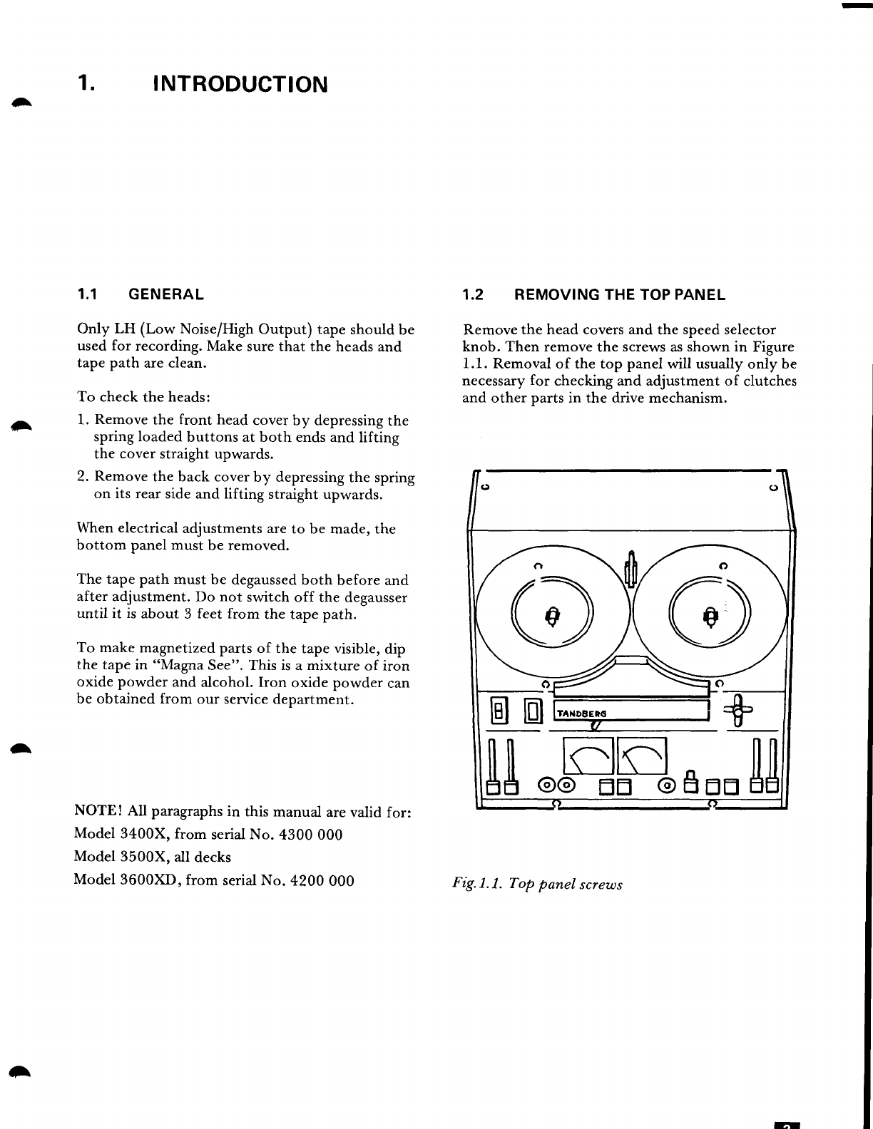
Removingthetoppanel . ......3
Maintenance.... ...,.,.4
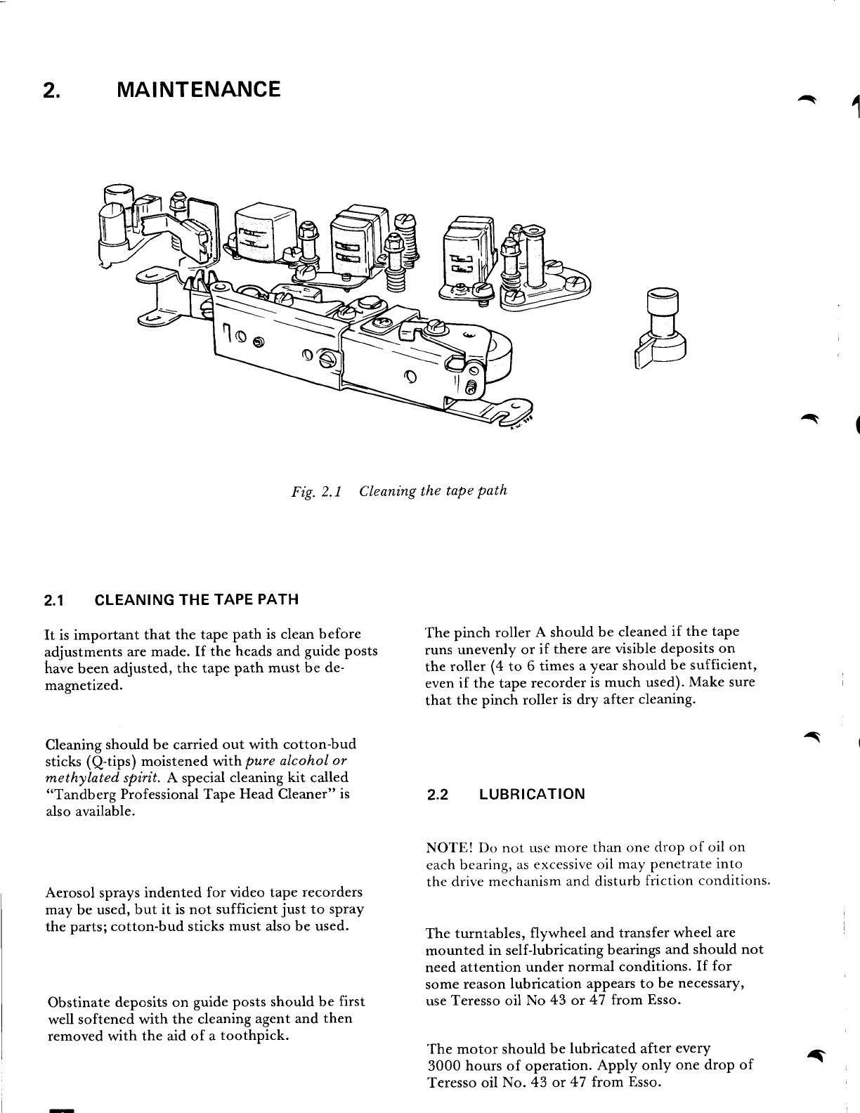
Cleaningthetapepath.. .......4
Lubrication .......4
Mechanicalchecksandadjustments.. .......5
Checking
the take-upforce andwinding force. . . . . . 5
Adjustingthetake-upforce. ....5
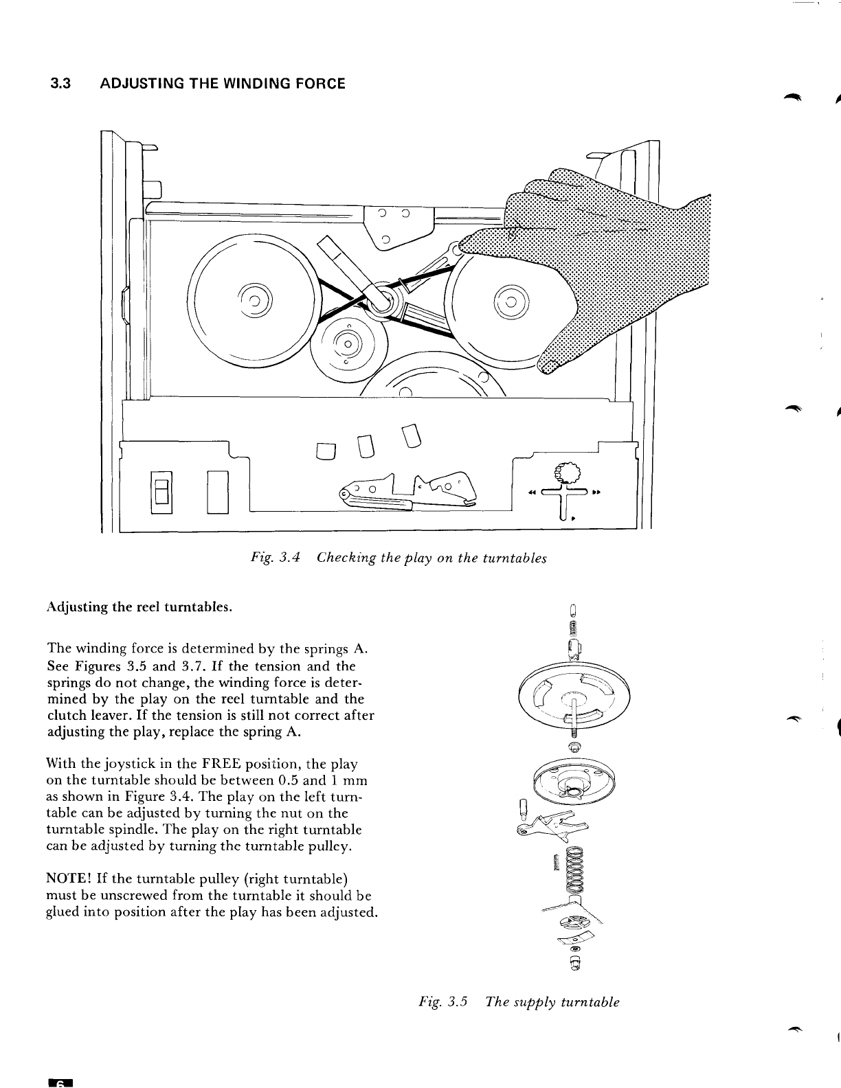
Adjustingthewindingforce. ...6
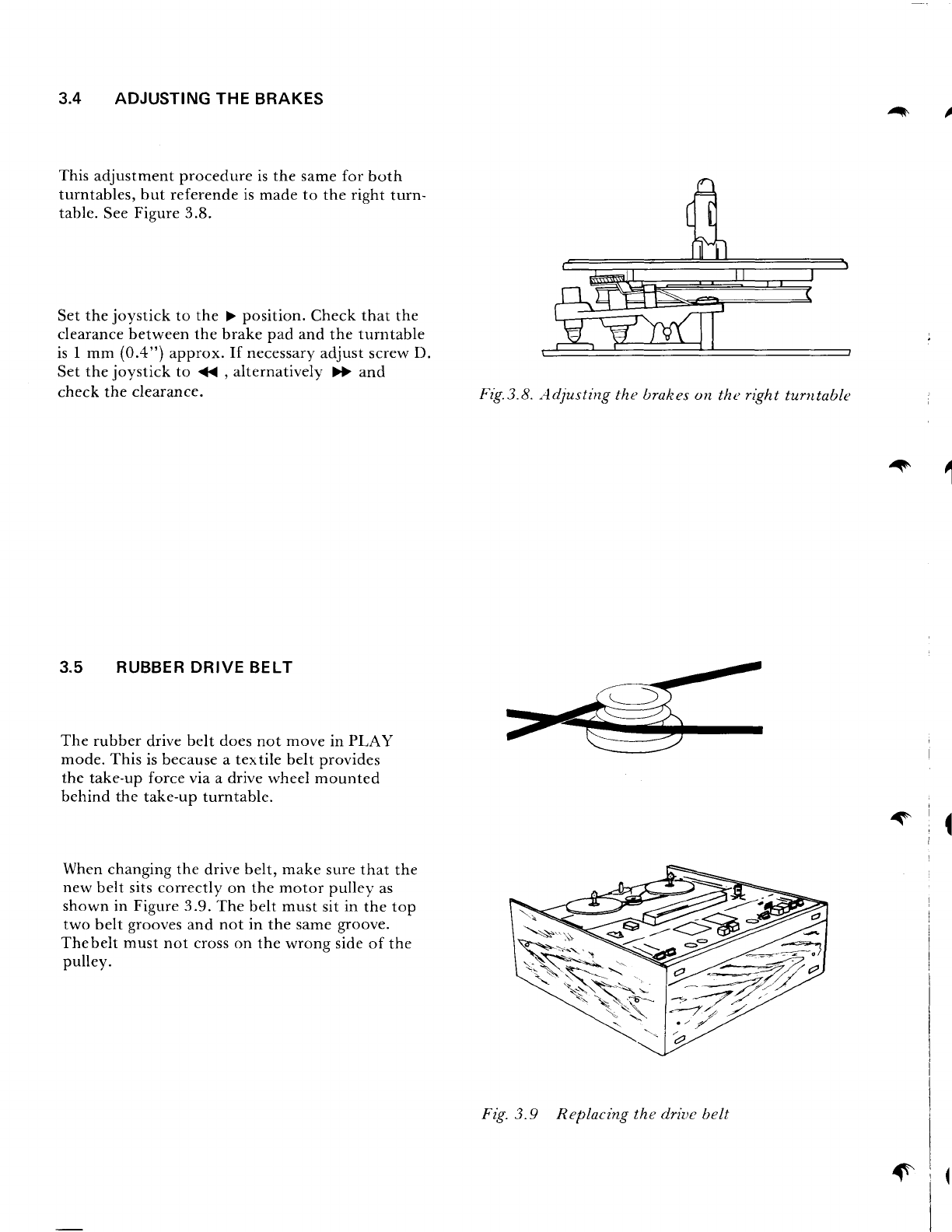
Adjustingthebrakes .....8
Rubberdrivebelt .......8
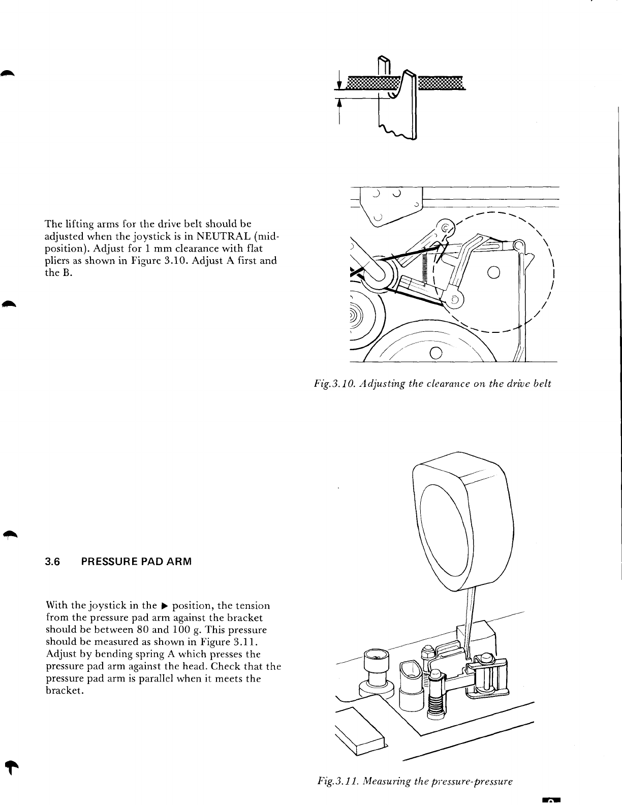
Pressurepadarm ...9
Tapepath ...10
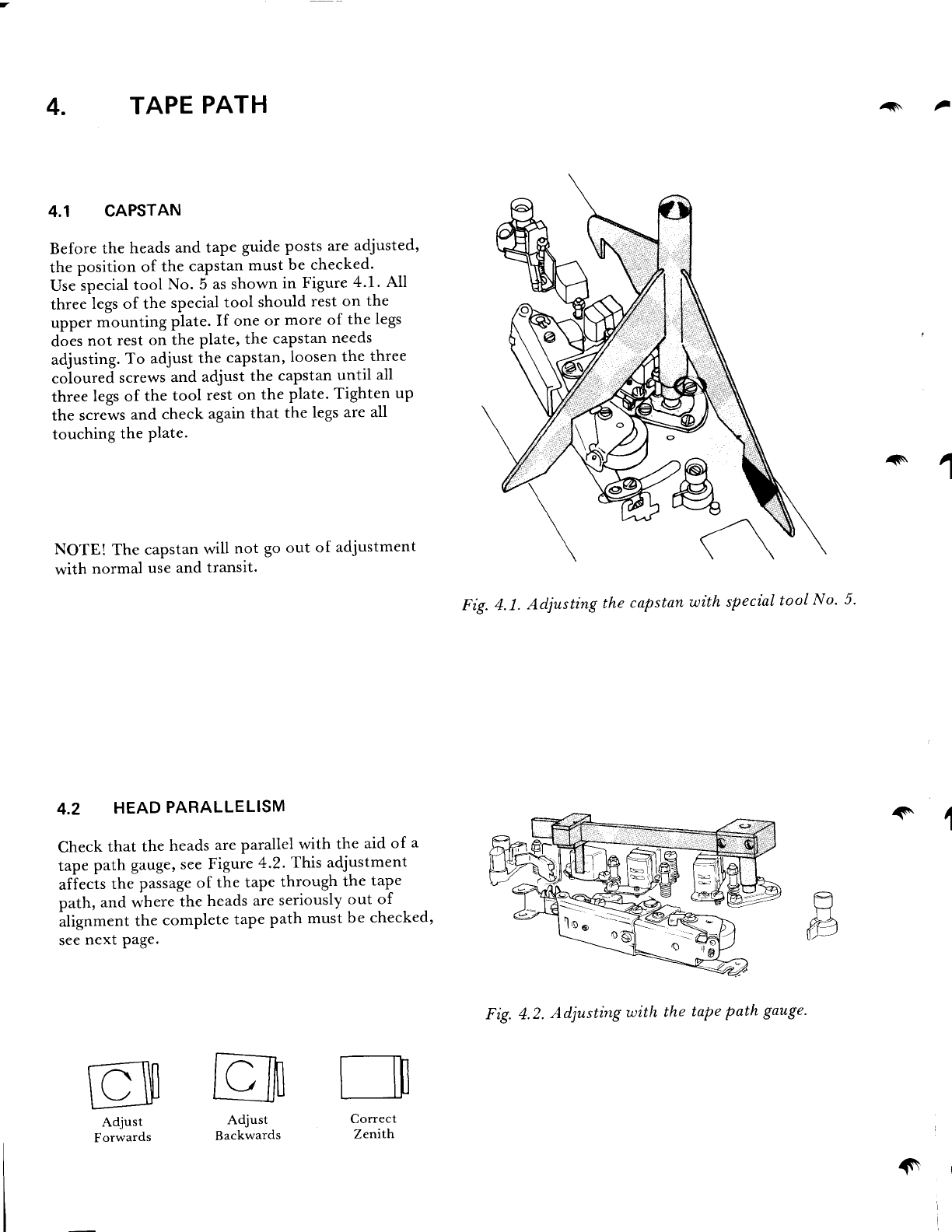
Capstan .....10
Headparallelism. .......10
Tapeguideposts
and
guide
screws.
.. .. .. . . .11
Pinchroller .......11
Flutterroller. .....12
Head
alignment
with Tandberg
test tapes,
four tracks . . . . .13
Playbackhead. ....13
Recordhead. .....13
Height
adjustmentby
trackmeasurement... ......13
Biashead ....I4
Erasehead ...I4
Headalignment
without Tandbergtest tapes,
four tracks . . . . . . .15
Playbackhead. ....15
Recordhead. .....15
Biashead ....15
Erasehead. .......15
Aligning the hum shieldfor the playback head. . . . .15
Headalignment,two
tracks .....16
Playbackhead. ...16
Recordhead. .....16
Erasehead ........17
Circuits .....77
Oscillator. . . .I7
Photoend-stop ........I7
Recordandplaybackfrequencyresponses . . .18
Faultinthetotalresponse
curve,onechannel..... ......19
Modifications... .......20
Changingthelinevoltageand
frequency... .......20
Changingfrom four tracksto two tracksversion . . . .20
Blockdiagrams ....20
Electricaladjustments.... .....22
Outputamplifiers
(3400X) .....22
Dolby*leveladjustments
(3600XD). .......22
Adjustments,allmodels.... ...23
Circuitdiagrams .... from page24
* Theword Dolby isa Trade
Mark of Dolby LaboratoriesInc., USA
-----.....-
-
t
a