T&S B-0114-01 User manual
LimitedOneYearWarranty
T&Swarrants totheoriginalpurchaser(other
than for purposes of resale) that such product
is free from defects in material and workman-
ship for a period of one (1) year from the date
of purchase. During this one-year warranty pe-
riod,iftheproductisfound to bedefective,T&S
shall, at its options, repair and/or replace it. To
obtain warranty service, products must be re-
turned to…
T&S Brass and Bronze Works, Inc.
Attn: Warranty Repair Department
2 Saddleback Cove
Travelers Rest, SC 29690
Shipping,freight,insurance,andothertrans-
portation charges of the product to T&S and
thereturnofrepaired orreplacedproducttothe
purchaser are the responsibility of the pur-
chaser. Repair and/or replacement shall be
made within a reasonable time after receipt by
T&Softhereturnedproduct.Thiswarrantydoes
not cover Items which have received second-
ary finishing or have been altered or modified
after purchase, or for defects caused by physi-
cal abuse to or misuse of the product, or ship-
ment of the products.
Any express warranty not provided herein,
and any remedy for Breach of Contract which
might arise, isherebyexcluded and disclaimed.
Any implied warranties of merchantability or fit-
ness for a particular purpose are limited to one
year in duration. Under no circumstances shall
T&Sbeliable for lossof use orany special con-
sequential costs, expenses or damages.
Some states do not allow limitations on how
long and implied warranty lasts or the exclu-
sion or limitation of incidental or consequential
damages,sotheabovelimitationsorexclusions
may not apply to you. Specific rights under this
warranty and other rights vary from state to
state.
P/N: 098-003154-45 Rev 4
Date: 990922
Drawn: TME
Checked: MAB11-12-99
Approved: MVW11-13-99
Installationand
Maintenance
Instructions
PRE-RINSEUNIT
(DECKMOUNTED)
B-0114-01
(AlsoforB-0114-01B,B-0114-02,B-0114-03,
B-0124,B-0134,&B-2362)
Deutsch: Installations- und
Wartungsanleitungen
Español: la Instalación y las
Instrucciones de
Mantenimiento
Français: les Instructions
d’Installation et
d’Entretien
2
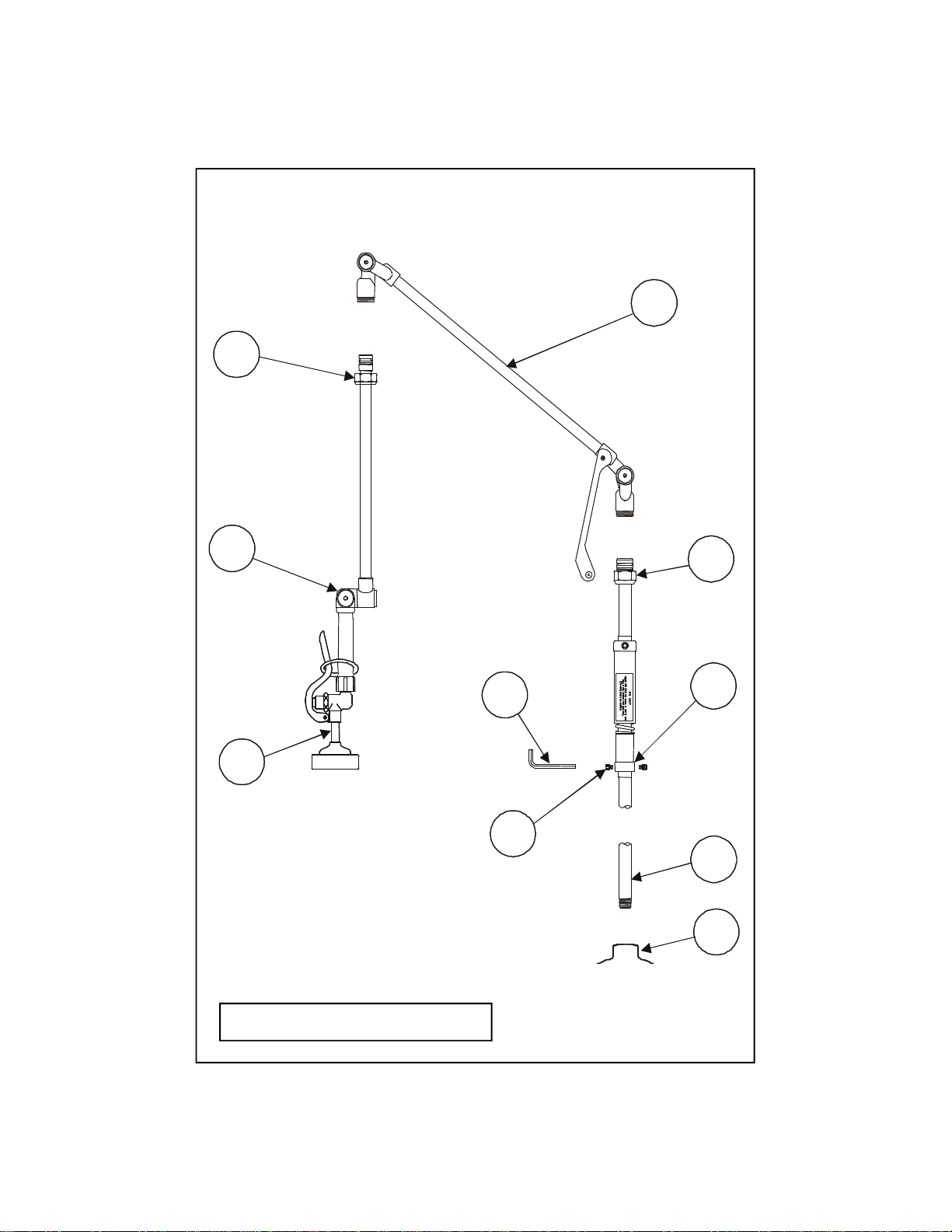
ExplodedView
*Some items are listed for instructional
purposes and may not be sold as separate parts.
9
3
10
4
2
85
6
1
7
T&S
BRASS

PartNumberGuide
3
Pre-Rinse Unit
1Asm, Spray Valve
B-0114-01,-02,-03, B-0124, B-0134
B-0107
B-0114-01C, -02C, -03C
B-0107-C
3Asm, Upper Arm 009490-40
2Asm, Knuckle Elbow 009184-40
9Swivel Nut 000702-40
10 Swivel Nut With Seal 000703-40
4Support Bushing 000616-40
5Asm, Knuckle Riser
B-0114-01, B-0124 (29”) 009178-40
B-0114-02, B-0134 (23”) 009182-40
B-0114-03 (19”) 009183-40
6Asm, Faucet
B-0114 Unit (B-0111 Fct.) 002824-40
B-0124 Unit (B-0121 Fct.) 002829-40
B-0134 Unit (B-0131 Fct.) 002832-40
7Key, Hex 001409-45
8Set Screw 000942-45
‘O’-Ring Kit – 010190-45
11 O-Ring (4) 001060-45
12 Snap Ring (2) *
13 #111 O-Ring Grease *

4
T&S
BRASS
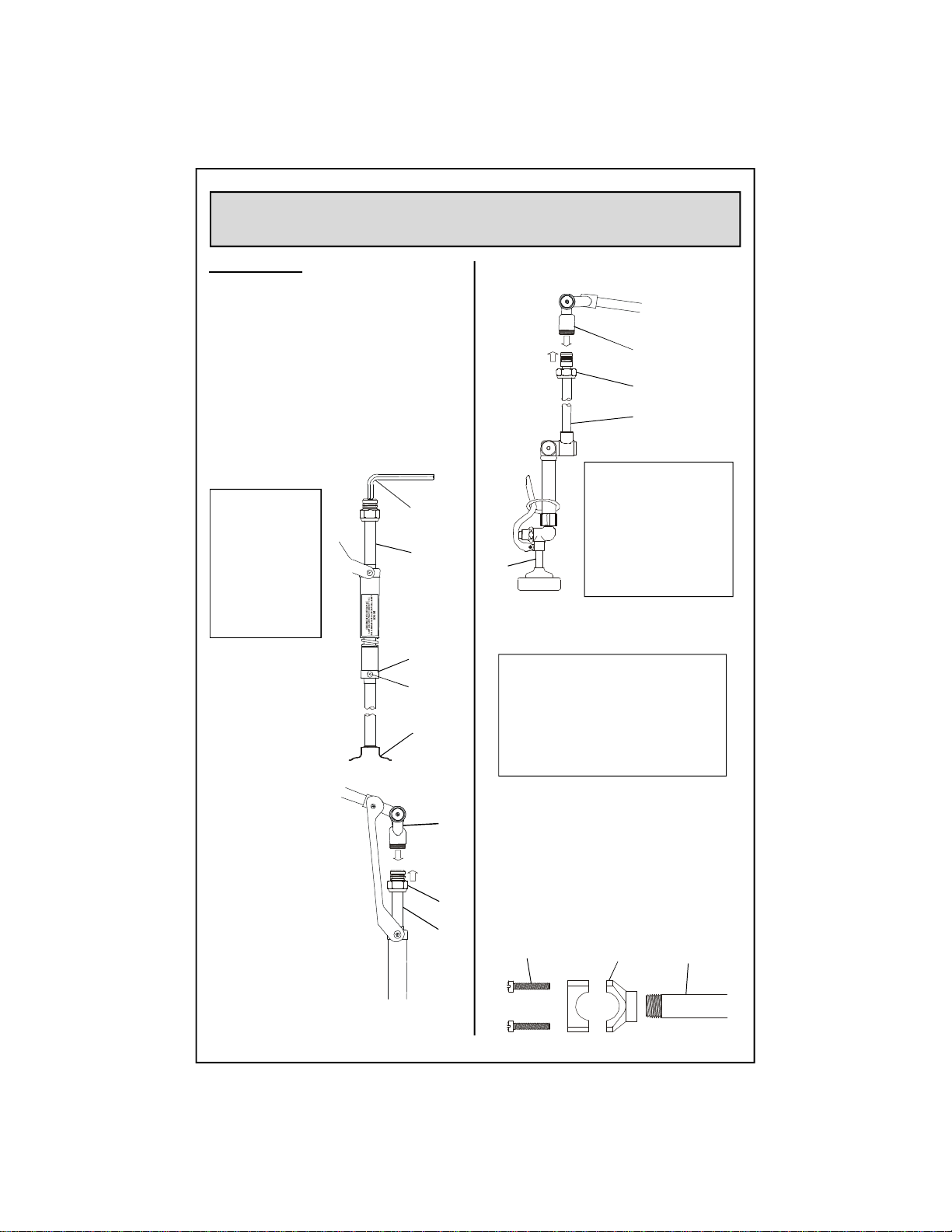
Installation:
See separate installation instruction for
installation of no.6into deck.
1. Shut off water supply and drain lines.
Apply teflon tape or pipe joint
compound to threads on both ends of
no.5. Screw no.5into no.6and
tighten with no.7.
GeneralInstructions
2. Remove no.7(do not
remove grease from
parts) and place no.3
on top of no.5.
3. Screw no.10 onto no.3
and tighten with a
wrench.
Note: Before
tightening no.9.
Check position of
no.1. Handle
should face front
towards the
operator.
Note: Do not
adjust no.8in
no.4. If unit is
too high, a new,
shorter no.5
pipe should be
orderedfrom
T&S.
4.For attachmentofno.2andno.3.
Screw no.9onto threaded end of no.3
andtightenwith awrench.
5. Turn on water supply and check for
leaks.
Optional Wall Bracket
Note: T&S highly recommends
installing a B-0109-01 Wall Bracket
with these Pre-Rinse Units (included
with the B-0114-01B and the B-2362
units). It must be ordered separately
with other models.
The B-109-01 Wall Bracket should be
installed after entire unit is assembled.
Fit bracket on no.5as high as possible.
Cut off any excess nipple as needed, and
mount to wall.
7
5
4
8
6
3
10
5
1
3
9
2
Nipple
Clamp
Screws

5
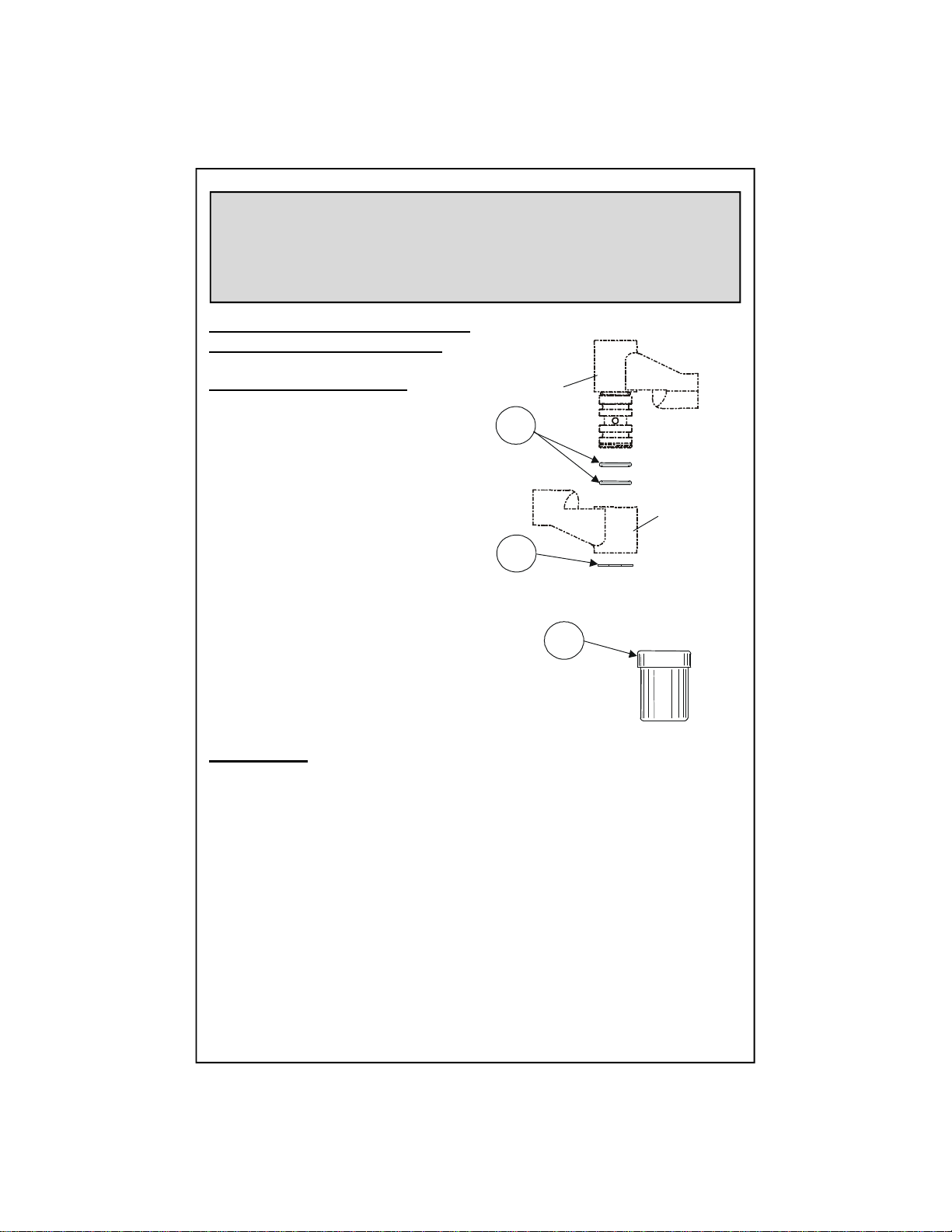
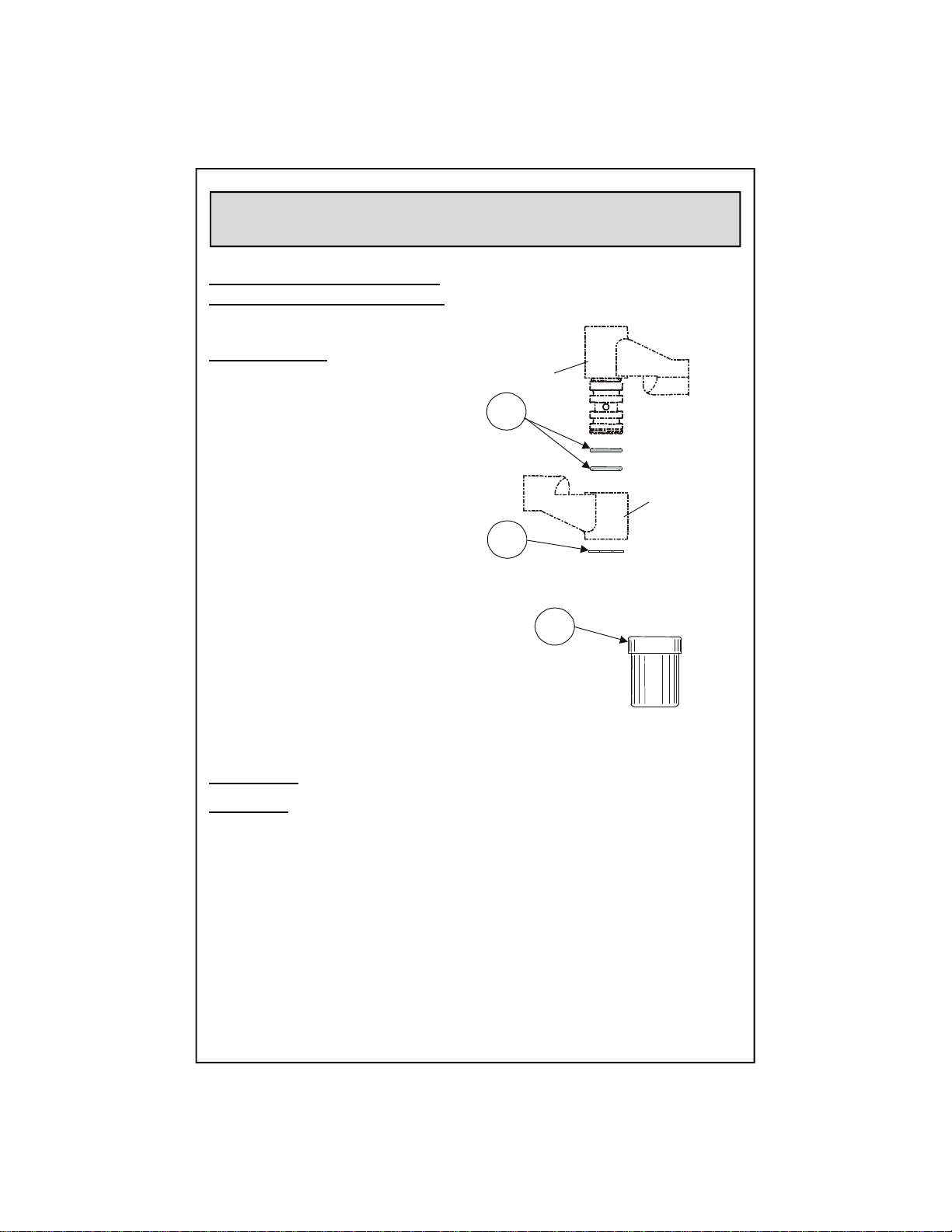
InstructionsForRepairKits
For 010180 Pre-RinseAssembly
Repair:
1. Usingretaining ringpliers, remove
and discard no.12 from each knuckle
on no.3.
2. Slide Knuckle ‘B’ off shaft. Remove
no.11 and discard, then clean parts and
inspect for damage. If deep scoring
exists, parts must be replaced.
3. Apply thin coat of no.13 to shaft.
Assemble new no.11 onto shaft and
apply a coat of no.13 to no.11.
4. Replace Knuckles and assemble new
no.12.
5. Reassemble unit and check for leaks.
Servicing:
Riser Assembly
1. Loosen the two screws on the B-0109Wall BracketClamp.
2. Unscrewno.9from no.3. Disassemble no.5fromno.6.
3. Loosenno.8on no.4. Carefully slide components from no.5.
4. Inspect no.5for damage. Inspect the spring for cracks. Replace if necessary.
Apply no.13 to no.11 and reassemble.
5. Reassemble no.5intono.6 andtighten with a wrench.
6. Tighten clamp screwson B-0109WallBracket.
7. Connect water supplylines andcheck for leaks.
Knuckle
‘A’
Knuckle
‘B’
13
12
11

6
Installatión:
La instalación de la parte No.6en
mostrador, se puede hacer siguiendo
las direcciones explicadas en otras
instruccionesseparadas.
1. Cierre la fuente principal de agua y
desague las tuberias. Aplique a las
roscas de ambos lados de la parte No.5
cintas para roscas de tubería o
compuesto de coyuntura
detubería,atornille la
parte No.5 en la parte
No.6y aprete con
la parte No.7.
2. Remueva la parte
No.7(no quite la grasa
de las partes) y
coloque la parte No.3
sobre la parte No.5.
3. AtornilleNo.10
sobre No.3y aprete
con una llave.
4. Paraarmar la parte
No.2y No.3.Atornille
la parte No.9en el
extreme opuesto de la
parte No.3y aprete
con una llave.
5. Abra la fuente de agua e
inspeccione por filtraciones.
Soporte Opcional Con Montadura Para
LaPared
Nota: Esaltamenterecomendado
por T&S que se instale el soporte
B-0109-01 con las unidades de
enjuagar (incluido con las unidades
B-0114-01B y B-2362). Para otros
modelos tendrá que ser ordenados
separadamente.
El soporte B-109-01 debe ser instalado
después de que la unidad esté
completamente armada. Acomode el
soporte en la parte No.5 lo más alto
posible. A medida necesitada corte el
exceso de tubo y encajelo a la pared.
Nota: No ajuste
la parte No.8en
la parte No.4. Si
la unidad esta
muy alta se debe
deordenar de
T&S un tubo
No.5más corto.
Nota: Antes de
apretar la parte No.9,
inspeccione la
posición de la parte
No.1. La manigueta
debedeestar
orientada al frente,
hacia el operador.
InstruccionesGenerales
T&S
BRASS
7
5
4
8
6
3
10
5
3
9
2
Tubo
Abrazadera
Tornillo
1

7
InstruccionesParaEstuchesDeReparo
Para unidades de enjuagar 010180-40
Reparo de junta de chanela:
1. Con alicates para argollas
retenedoras, Remueva y arroje
la parte No.12 de cada chanela en
la parte No.3.
2. Deslize la chanela ‘B’ de el tubo.
Remueva la parte No.11 y arroje,
luego limpie las partes e
inspeccione por danos. Si existen
rayones profundos, la parte
tendrá que ser reemplazada.
3. Aplique una delgada capa de
la parte No.13 a el tubo. En el tubo
arme la parte nueva No.11 y aplique
una delgada capa de la No.13 en
la parte No.11.
4. Reemplaze las chanelas e instale
la parte nueva No.12.
5. Ensamble de nuevo la unidad e
inspeccione por filtraciones.
Mantenimiento:
Ensamble de extensión
1. Afloje los dos atornillos en el soporte B-0109-01.
2. Destornille la parte No.9de la parte No.3. Desarme la parte No.5de la parte No.6.
3. Afloje la parte No.8en la parte No.4. Cuidadosamente deslize los componentes
de la parte No.5.
4. Inspeccione la parte No.5por daños. Inspeccione el resorte por grietas.
Reemplazelo si es necesario.Aplique de la parte No.13 a la No.11 y arme
de nuevo.
5. Arme de nuevo la parte No.5en la parte No.6 y aprete con una llave.
6. Aprete los tornillos de soporte B-0109-01.
7. Conecte la tubería principal e inspeccione or filtraciones.
Junta
‘A’
Junta
‘B’
13
12
11

8
Le Support du Mur Facultatif
Noter: T&S vons conseiller
l’installtion d’un B-0109-01 support
du mur avec ces éléments pre-rinçages
(inclus avec les elements
B-0114-01B et B-2362). Il falloir le
commander separément avec les
autres modèles.
Le B-109-01 support du mur devoir être
installer après l’assemblée de l’élément
entier. Mettre le support sur N°.5le plus
haut que possible. Couper l’excès de
tuyaux comme nécessaire et monter au
mur.
InstructionsGénérales
L’Installation:
Voir la feuille d’instruction separée pour
l’installation de N°.6dansl’égouttoir.
1. Fermer la réserve de l’eau et égoutter
la tuyauterie.Appliquer leruban en
Téflon ou le composé pour les joints de
tuyauxa chaque extrémité de N°.5.
Visser N°.5dans N°.6et resserrer avec
N°.7.
2. EnleverN°.7
(n’enlever pas la
graisse des parties)
etmettre N°.3au
dessus de N°.5.
3. VisserN°.10 sur
N°.3et resserrer
avec une clef.
4. Pour attacher N°.2et
N°.3.Visser N°.9dans
l’autreextrémitéde N°.3
et resserrer avec une clef.
5. Recommencer l’eau et vérifier s’il ya
des fuites.
Noter:
N’adjuster pas
N°.8dans N°.4.
si l’élément être
trop haut un
nouveau, plus
cort, N°.5tuyau
devoir être
commander de
T&S.
Noter: Avant
resserrerN°.9.
Vérifier la position
deN°.1. La
poignéedevoir
être en face de
l’opérateur.
1
3
9
2
tuyaux
serre-jointVis
T&S
BRASS
7
5
4
8
6
3
10
5
9
InstructionsPourLes
TroussesàOutils
Pour les éléments pre-rinçages utilisant
la 010180 assemblée de bras-dessus
La Réparation de la Jointure:
1. Utiliser les pinces nécessaires,
enlever et mettre au rebut N°.12 de
chaque jointure sur N°.3
2. Faire glisser la jointure ‘B’ du
manche. Enlever N°.11 et mettre au
rebut, puis nettoyer les parties et
inspecter pour le dommage. Si les
entailles profondes exister, les parties
devoir être remplacer.
3. Appliquer une couche mince de
N°.13 au manche. Assembler un
nouveau N°.11 sur le manche et
appliquer une couche de N°.13 a N°.11.
4. Remplacer les jointures et installer un nouveau Nº.12.
5. Réassembler l’element et vérifier s’il y a des fuites.
L’Entretien: L’assemblée de l’augmentation
1. Desserrer les deux vis sur le B-0109 serre-joint du support du mur.
2. Dévisser N°.9de N°.3. Désassembler N°.5de N°.6.
3. Desserrer N°.8sur N°.4. Prudemment, faire glisser les parties de N°.5.
4. Inspecter N°.5pour le dommage. Inspecter le ressort pour les fissures.
Le remplacer si nécessaire. Appliquer N°.13 to N°.11 et réassembler.
5. Réassembler N°.5dans N°.6 et resserrer avec une clef.
6. Resserrer les vis sur le B-0109 support du mur.
7. Brancher la tuyauterie et vérifier s’il y a des fuites.
la Jointure
‘A’
la Jointure
‘B’
13
12
11
10
Optionaler Wandarm
Anmerkung: T&S empfiehlt, mit
diesen Vorspülgeräten (bei
B-0114-01B und B-2362
eingeschlossen) einen B-0109-01
Wandarm zu installieren. Bei
anderen Modellen muß er separat
bestellt werden.
Der B-109-01Wandarmwirdinstalliert,
nachdemdieganze Einheit
zusammengesetzt worden ist. Wandarm
auf Nr. 5so hoch wie möglich
anbringen. Überflüssige Nippel nach
Bedarf abschneiden und an der Wand
anbringen.
AllgemeineAnleitungen
Installation:
Nr. 6denseparatenAnleitungen
entsprechend auf die Abdeckplatte
montieren.
1. Wasser abdrehen und
Wasserleitungen entleeren. Teflonband
oder Rohrkitt an beiden Seiten des
Gewindes vonNr. 5anbringen.Nr. 5in
Nr. 6einschraubenund mitNr. 7
festdrehen.
Anmerkung: Vor dem
Festschraubenvon
Nr. 9. Stellung von
Nr. 1überprüfen.Der
Griff sollte nach vorn
in Richtung des
Bedieners zeigen.
2. Nr. 7entfernen
(Schmierenicht von
denTeilen entfernen)
undNr. 3auf Nr. 5
plazieren.
3. Nr. 10 aufNr. 3
hinaufschieben und
mit
Schraubenschlüssel
festdrehen.
4. UmNr. 2und Nr.3
miteinanderzu verbinden,
Nr. 9indasGewindeenda
von Nr. 3schrauben und
miteinem
Schraubenschlüssel
festdrehen.
Anmerkung: Teil
Nr. 8nicht in
Nr. 4justieren.
Falls Einheit zu
hoch ist, ist
kürzeresRohr
Nr. 5vonT&S
zu bestellen.
5. Wasser andrehen und auf Lecks
prüfen.
1
3
9
2
Nippel
Klammer
Schrauben
T&S
BRASS
7
5
4
8
6
3
10
5
11
AnleitungenfürReparaturwerkzeug
Für bestehende Vorspüleinheit, die
die 010180 Oberarmeinheit benutzt
Gelenkreparatur:
1. Mit Beibzange mit Sicherungsring
Nr. 12 vonjedemGelenk auf Nr. 3
entfernen.
2. Ziehen Sie das Gelenk ‘B’ vom Schaft.
Nr. 11 entfernenund wegwerfen, dann
Teile reinigen und auf Schaden
untersuchen. Falls tiefe Einkerbungen
bestehen, mussen die Teile ersetzt
werden.
3. Dünne Schicht Nr. 13aufSchaft
auftragen. Neues Nr. 11 aufSchaft
aufmontieren und eine Schicht Nr. 13 auf
Nr. 11 auftragen.
4. Gelenke ersetzen und neues Nr. 12
installieren.
5. Einheit zusammensetzen und auf
Lecks prüfen.
Bedienung:
Steigleitung
1. Diebeiden Schrauben der Wandarmklammer B-0109 losschrauben.
2. Nr. 9von Nr. 3abschrauben.Nr. 5von Nr. 6entfernen.
3. Nr. 8auf Nr. 4lossschrauben. Die Teile sorgfältig von Nr. 5abschieben.
4. Nr. 5auf Schäden überprüfen. Die Feder auf Risse untersuchen. Falls
notwendig ersetzen. Nr. 13 auf Nr. 11 aufsetzen und wieder zusammensetzen.
5. Nr. 5inNr. 6einsetzen und mit Schraubenzieher festziehen.
6. DieKlammerschrauben des WandarmsB-0109festziehen..
7. Wasserleitung wieder verbinden und auf Lecks untersuchen.
Gelenk
‘A’
Gelenk
‘B’
13
12
11

T&SBRASSANDBRONZEWORKS,INC.
A firm commitment to application-engineered plumbing products
2 Saddleback Cove, P.O. Box 1088, T & S Brass-Europe
Travelers Rest, SC 29690 ‘De Veenhoeve’
Phone: (864) 834-4102 Oude Nieuwveenseweg 84
Fax: (864) 834-3518 2441 CW Nieuwveen
B-0114-RK
REPAIR KIT
PRE-RINSE UNIT
B-0134
PRE-RINSE UNIT
W/ WALL MOUNTED
FAUCET
This manual suits for next models
6
Table of contents
Languages:
Other T&S Industrial Equipment manuals

Popular Industrial Equipment manuals by other brands


SkoFlo Industries
SkoFlo Industries SF10000HTVB Operation and maintenance manual

3M
3M Liqui-Cel EXF-14 28 Series Assembly and disassembly instructions

Wizard
Wizard FS Operating and service manual

ABB
ABB HT582447 Operation manual

Festo
Festo VTEM manual

PAW
PAW HeatBloC K32 Installation and operation instruction


