T&S B-0968 User manual

Installationand
Maintenance
Instructions
ATMOSPHERIC
VACUUM BREAKERS
B-0968 (3/8”) & B-0969 (1/2”)
(Also use for replacement parts,
B-0968-RK013/8”&B-0969-RK011/2”)
Deutsch: Installations-und
Wartungsanleitungen
Español: la Instalación y las
Instruccionesde
Mantenimiento
Français: lesInstructions
d’Installationet
d’Entretien
Limited One Year Warranty
T&Swarrantstotheoriginalpurchaser(otherthan
forpurposesofresale)thatsuchproductisfreefrom
defectsinmaterialandworkmanshipforaperiodof
one(1)yearfromthedateofpurchase. Duringthis
one-yearwarrantyperiod,iftheproductisfoundto
bedefective,T&Sshall,atitsoptions,repairand/
orreplaceit. Toobtainwarrantyservice,products
mustbereturnedto...
T&SBrassandBronzeWorks,Inc.
Attn: WarrantyRepairDepartment
2SaddlebackCove
TravelersRest,SC 29690
Shipping,freight,insurance,andothertranspor-
tationchargesoftheproducttoT&Sandthereturn
ofrepairedorreplacedproducttothepurchaserare
theresponsibilityofthepurchaser. Repairand/or
replacementshallbemadewithinareasonabletime
afterreceiptbyT&Softhereturnedproduct. This
warrantydoesnotcoverItemswhichhavereceived
secondaryfinishingorhavebeenalteredormodi-
fiedafterpurchase,orfordefectscausedbyphysi-
calabusetoormisuseoftheproduct,orshipment
oftheproducts.
Anyexpresswarrantynotprovidedherein,and
anyremedyforBreachofContractwhichmightarise,
is hereby excluded and disclaimed. Any implied
warrantiesofmerchantabilityorfitnessforaparticu-
larpurposearelimitedtooneyearinduration. Under
no circumstances shall T&S be liable for loss of
useoranyspecialconsequentialcosts,expenses
ordamages.
Somestatesdonotallowlimitationsonhowlong
andimpliedwarrantylastsortheexclusionorlimi-
tationofincidentalorconsequentialdamages,so
theabovelimitationsorexclusionsmaynotapply
toyou. Specificrightsunderthiswarrantyandother
rightsvaryfromstatetostate.
P/N: 098-009549-45 Rev.3
Date: 980120
Drawn: CW
Checked: JLT 4-14-98
Approved: MW 4-14-98
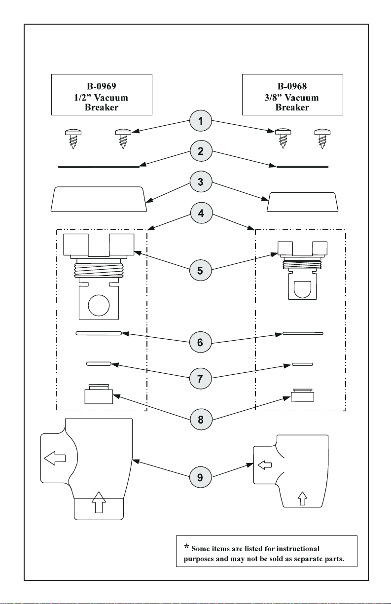
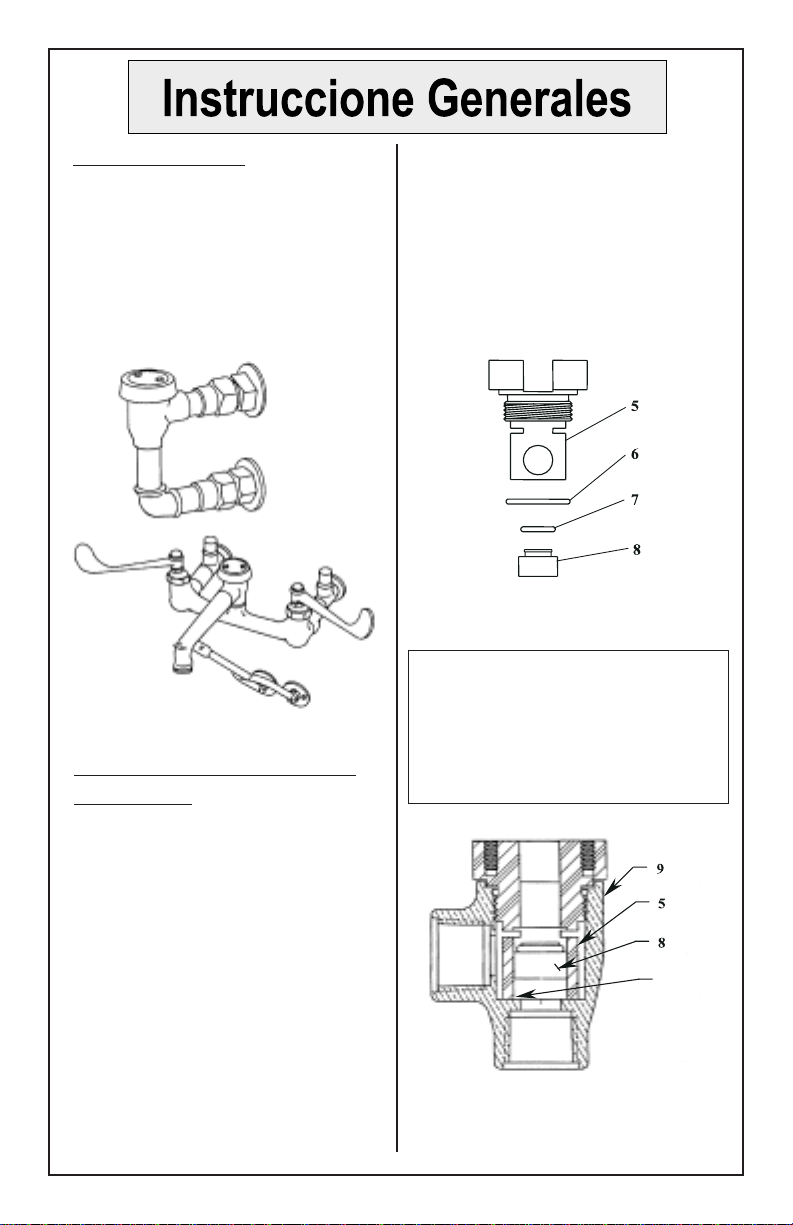
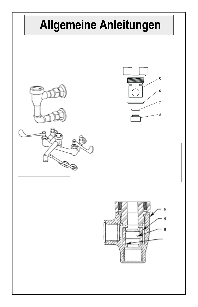
Exploded View

Part Number Guide
Vacuum Breaker Assemblies & Kit
1 Screw, Self-tapping V.B. *
2 Namplate (3/8" or 1/2") *
3 Coverplate (3/8" or 1/2") *
4 Repair Kit 3/8" V.B. B-0968-RK01
5 Insert 009785-45
6 O'-Ring, Insert *
7 O'-Ring, Plunger 001066-45
8 Piston (3/8" V.B.) 009525-45
4 Repair Kit 1/2" V.B. B-0969-RK01
5 Insert 009786-45
6 O'-Ring, Insert *
7 O'-Ring, Plunger 010488-45
8 Piston (1/2" V.B.) 009527-45
9 Body, Vacuum Breaker - 3/8" or 1/2" *
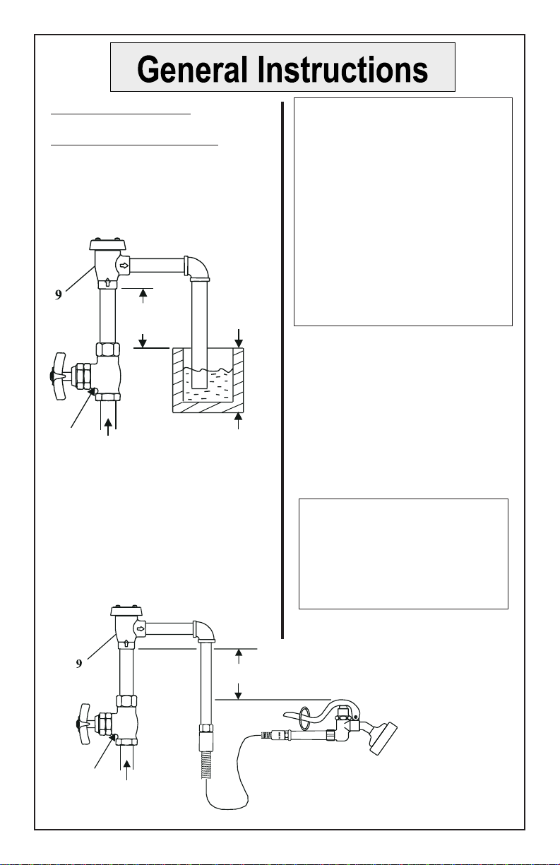
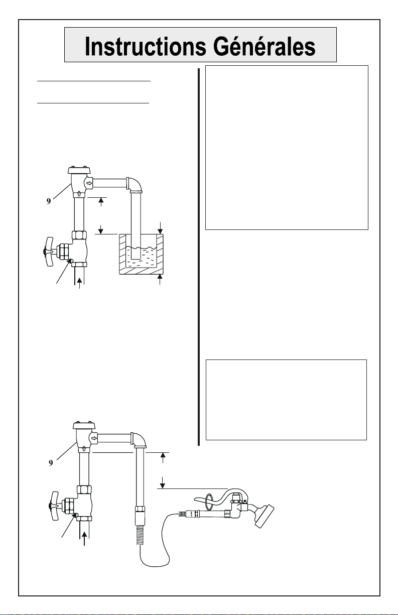
TypicalInstallation:
SingleVacuum Breaker
1. Vacuum breaker must be installed
with the supply connected to the
bottom and the outlet connected to
the appliance, as shown below:
2. The bottom of the no.9should be
at least 6” above the flood rim of the
fixtureorappliance.
3. When using a portable appliance,
no.9should be installed at least 6”
above the highest point to which the
outlet can be raised, as shown:
Note: Where the device is a
separate unit, in the absence of a
Critical Installation Level (CIL)
mark, the extreme bottom of the
no.9 casting should be used to
determine its installed position.
Where the device is incorporated
in an outlet tube furnished by the
manufacturer, the extreme bottom
of the internal unit should be
noted on the outside of the tube by
a CIL line, for use in determining
its installed position.
4. The water supply valve must be
installed on the supply side (ahead)
of the vacuum breaker, and no shut-
off valve should be installed on the
outlet side (downstream).
5. The vacuum breaker should not be
subjected to continuous pressure for
more than twelve (12) hours.
Note: This device should not be
installed in a concealed or
inaccessible location, nor where
the venting water from the device
during its normal functioning
may be deemed objectionable.
not less than
6” (CIL)
supply
valve fixture or
appliance
overflow
or flood
rim
highest position of appliance
not less than 6” (CIL)
supply
valve
TypicalInstallation:
Follow the instructions in the Single
Vacuum Breaker section, Step 1 thru
step 5.
Two typical T&S unit installations
willlook asfollows:
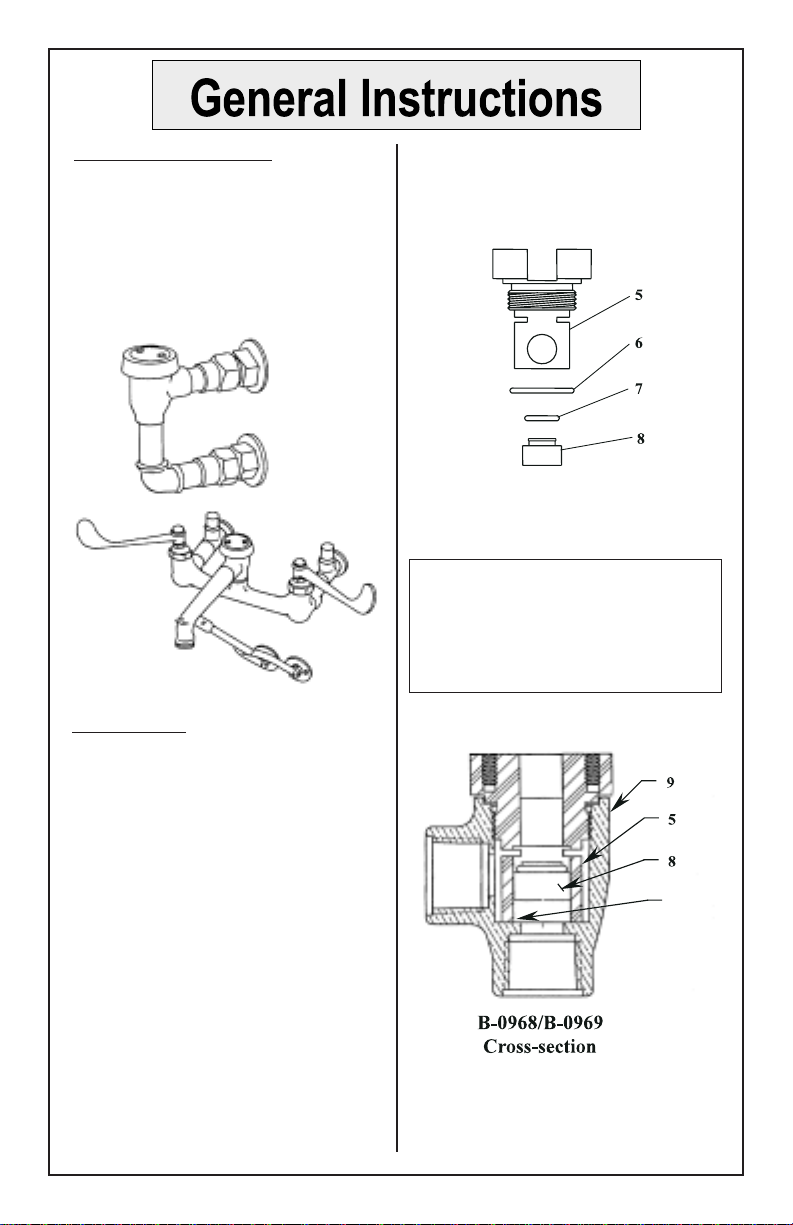
RepairKit:
1. For replacement parts, reorder
complete unit, or replace internal
parts with a repair kit for your specific
modelVacuumBreaker:
B-968-RK01 3/8” Vac. Breaker
B-969-RK01 ½” Vac. Breaker
2. (See exploded view shown above.)
Remove the two no.1from top of
no.3, and lift off no.2and no.3.
3. Unscrew and remove no.5,no.6,
no.7 and no.8from inside no.9.
4. Replace parts with new parts from
kit.
B-929 Atmospheric Vacuum
Breaker Assembly
5. Reassemble in reverse order.
Note: Make sure surface inside the
body (as indicated below) is clean,
and then tighten no.5until it is
firmly seated against the inside
shoulder of no.9.
B-0968-RK01 (Kit)
3/8” Vac. Breaker
B-657
ServiceSink
Faucet
B-0969-RK01 (Kit)
1/2” Vac. Breaker
or
make
sure
this
surface
is clean
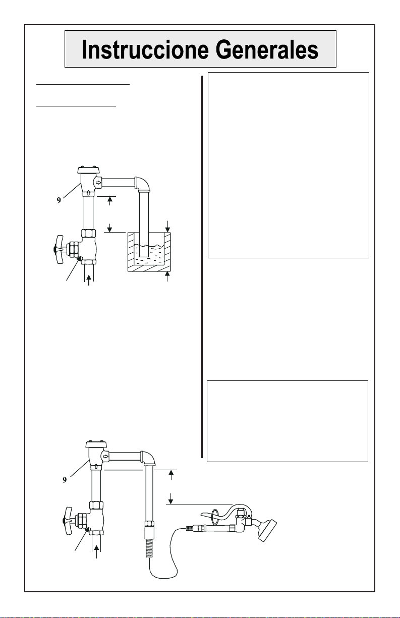
InstalaciónTípica:
Anti-sifónsingular
1. La válvula anti-sifón tiene que ser
instalada, con la fuente surtidora en la
parte posterior y la salida conectada a
la aplicación, como se muestra abajo:
2. El lado posterior de la parte No.9
debe ser por lo mínimo 15.24cm sobre
el caño de reboso del accesorio ó
aplicación.
3. Cuando esta utilizando una
aplicación portable, No.9debe ser
instaladapor lomínimo 15.24cmsobre
el punto más alto en que se pueda
levantar la salida, como esta
demostrado:
Nota: Donde el aparato sea una
unidad separada, en la ausencia de
la marca (CIL) que significa nivel
crítico de instalación, el lado
extremo posterior de la parte No.9
debe ser utilizado para determinar
la posición de instalación. Donde el
aparato sea incorporado en un tubo
de salida surtido por la factoría, el
lado extremo posterior de la unidad
interna debe ser señalada en la
parte de afuera del tubo por una
línea de CIL, para uso en
determinar su posición de
instalación.
4. La válvula de surtido tiene que
estar instalada en el lado del surtido
(adelante) de la válvula anti-sifón y
ninguna válvula de detención debe
ser instalada en el lado de salida
(abajo de la corriente).
5. La válvula anti-sifón no debe ser
sometida a presión continua por más
de doce (12) horas.
Nota: Este aparato no debe ser
instalado en un sitio escondido o
inaccesible, tampoco donde la
salida de agua del aparato durante
su función normal sea juzgado
perjudicial.
Válvula
Surtidora
No menos de
15.24 cm (CIL)
Derrame
ó caño de
reboso
Accesorio
ó
aplicación
Posición máxima de aplicación no
menos de 15.24cm (CIL)
Válvula
surtidora
InstalciónTípica:
Siga las instrucciones en la sección
de anti-sifón singular, los pasos
del 1 al 5.
Dos instalaciones de unidades tipicas
de T&S se verán como lo siguiente:
B-929 Ensamblado De Válvula
Anti-sifón Atmosférica
InstruccionesPara Estuches
De Reparo:
1. Para repuesto, ordenar la unidad
completa ó reemplazar partes internas
con un estuche de reparo para su
modelo especifico de válvula de Anti-
sifón.
B-968-RK01 3/8”
B-969-RK01 ½”
2.(Mire arribael dibujo amplificado).
Remueva las dos partes, No.1de la
parte de encima de la parte No.3, y
alze las partes No.2y No.3.
5. Arme de nuevo en orden reversa.
Nota: Asegúrese que la superficie
dentro del cuerpo (como esta
indicado abajo) esté limpia y aprete
la parte No.5hasta que aciente
firmemente contra el sostén interno
de la parte No.9.
B-0968-RK01 3/8”
Válvula Anti-sifón
B-657 Canilla
de sentina
3. Destornille y remueva las partes
No.5,No.6,No.7 y No.8del interior
de la parte No.9.
4. Reemplaze con partes nuevas del
estuche de reparo.
B-0969-RK01 1/2”
Válvula Anti-sifón
or
Asegúrese
que esta
superficie
esté
limpia
B-0968/B-0969
Cortetransversal
L’InstallationTypique:
La Vanne-Caisse-Vide
1. La vanne-caisse-vide devoir être
installer avec l’alimentation brancher
au fond et la sortie brancher à
l’appareil comme indiqué au-dessous:
Noter: Si le dispositif être un
élément séparé, avec l’absence
d’une ligne du Niveau de
L’Installation Critique (CIL), le
fond extrême de la coulée de N°.9
devoir être utiliser pour déterminer
sa position installée. Si le dispositif
être incorporer dans un tube de
sortie fourni par le fabricant, le fond
extrême de l’élément interne devoir
être noter a l’extérieur du tube par
une ligne CIL, pour déterminer sa
position installée.
4. Le soupape de la réserve de l’eau
devoir être installer au côté
d’alimentation (juste devant de) la
vanne-caisse-vide, et aucun soupape
de sureté devoir être installer au côté
de la sortie (en aval).
5. La vanne-caisse-vide ne devoir pas
être soumis à la pression continue
plus de douze (12) heures.
Noter: Le dispositif ne devoir pas
être installer ni dans un emplace-
ment caché ou inaccessible, ni où le
déchargement de l’eau du dispositif
pendant la fonction normale aller
être désagréable.
2. Le fond de N°. 9devoir être au
moins 15.24 cm au-dessus le bord-
inondation de l’appareil.
3. Quand on utiliser un appareil
portatif, N°. 9devoir être installer au
moins 15.24 cm au-dessus le point le
plus haut qu’on pouvoir lever la
sortie, comme indiqué.
Pas moins que
15.24cm (CIL)
Le Trop-plein ou
le bord-
inondation
Le Soupape de
la Réserve
Le Soupape de
la Réserve
L’appareil
La position la plus haute de l’appareil
pas moins 15.24 cm (CIL)

L’InstallationTypique:
Suivre les instructions dans la
section de la vanne-caisse-vide, de
l’étape 1 jusqu’ à l’étape 5.
Deux installations typiques des
éléments de T&S aller avoir l’aspect
comme indiqué au-dessous:
La Trousse À Outils:
1. Pour les parties remplacements,
commander un élément complet ou
remplacer les parties internes avec
une trousse à outils pour vôtre
modèle spécifique de la vanne-caisse-
vide. B-968-RK01 0,96 cm
B-969-RK01 1,28 cm
2. (Voir la vue-explosé indiqué au-
dessous.) Enlever les deux N°.1du
haut de N°.3, et lever N°.2et N°.3.
3. Dévisser et enlever N°.5,N°.6,N°.7
et N°.8de l’ intérieur de N°.9.
4. Remplacer les parties avec les
parties nouvelles de la trousse.
Soyez
certain
que la
superficie
est
propre.
B-0968/B-0969
LaCoupe
Transversale
5. Réassembler a l’ inverse.
Noter: Soyez certain que la
superficie de l’ intérieur (comme
indiqué au-dessous) être propre, et
puis resserrer N°.5jusqu’ il est
fermement contre l’épaule de l’
intérieur de N°.9.
B-0968-RK01
(Trousse) 0,96 cm B-0969-RK01
(Trousse) 1,28 cm
ou
B-929 la Vanne-Caisse-Vide
Atmosphérique
B-657 Le
Robinet De
L’Évier Service
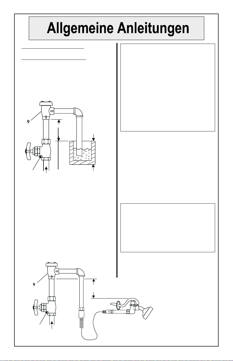
NormaleInstallation:
EinfacherVakuumschalter
1. Bei der Installation des
Vakuumschalters muß die Zuführung
wie gezeigt mit dem unteren Ende,
und das Ausflußrohr wie gezeigt mit
dem Gerät verbunden werden:
Anmerkung: Falls das Gerät eine
separate Einheit ist, ist, falls eine
kritische Einbauebene fehlt (CIL),
nach der Installation der äußerste
untere Rand des Gußstückens Nr.9 zur
Festlegung seiner Lage zu verwenden.
Falls das Gerät Teil eines Ausflußrohrs,
das vom Hersteller geliefert wird, ist, ist
der äußerste untere Teil der internen
Einheit auf der Außenseite des Rohrs
durch eine Linie für die kritische
Einbauebene zur Bestimmung seiner
Lage nach der Installation anzugeben.
4. Das Wasserzulaufventil muß an
der Zulaufseite vor dem
Vakuumschalter installiert werden
und auf der Ausflußseite (abwärts)
sollte kein Absperrventil installiert
werden.
5.DerVakuumschalter darf keinem
Dauerdruckvon mehrals zwölf(12)
Stunden ausgesetzt werden.
Anmerkung: Dieses Gerät darf nicht an
einer versteckten oder unzugänglichen
Stelle oder an einer Stelle, wo das
Ablaufen von Wasser aus dem Gerät
während des normalen Betriebs
beanstandet werden könnte, installiert
werden.
2. Das untere Ende von 9sollte
mindestens 15,24 cm über dem
Überflußrand der Vorrichtung oder
des Geräts liegen.
3. Wenn ein tragbares Gerät
verwendet wird, sollte Nr.9wie
gezeigt mindestens 15,24 cm über
dem höchsten Punkt, auf den das
Ausflußrohr angehoben werden
kann, installiert werden.
Überfluß- oder
Höchwasserrand
Nicht weniger als 15,24
cm (CIL) oberhalb der
kritischen Einbauebene
Vorrichtung
oder Gerät
Zuflußventil
Zuflußventil
Höchster Punkt des Geräts mindestens 15,24 cm
(CIL) oberhalb der kritischen Einbauebene
NormaleInstallation:
Die Anleitungen fur den einfachen
Vakuumschalter, Schritt 1 bis 5,
befolgen.
Die Installation von zwei typischen
T&S Einheiten sieht wie folgt aus:
B-929 Atmosphariche
Vakuumechalicrvorrichtung
B-657
Ausgußhahnvorrichtung
Instandsetzungssatz:
1.Für Ersatzteilekomplette Einheit
bestellen oder interne Teile mit einem
Instandsetzungssatz für lhr spezielles
Vakuumschaltermodellersetzen:
B-968-RK01 0,96 cm
B-969-RK01 1,28 cm
2. (Siehe Darstellung in
auseinandergezogener Anordnung
oben.) Die beiden Teile Nr.1von der
Oberseite von 3entfernen und Nr.2
und 3abheben.
3. Nr.5, 6, 7 und 8 von der Innenseite
von Nr.9losschrauben und
entfernen.
4. Teile durch neue Teile des
Instandsetzungssatzes ersetzen.
5. In umgekehrter Anordnung wieder
zusammensetzen.
Anmerkung: Sicherstellen, daß die
Oberfläche innerhalb des Gehäuses
(wie unten angegeben) sauber ist,
und dann Nr.5festdrehen, bis der
Teil fest gegen die innere Schulter
von Nr.9ansitzt.
Sicher-
stellen,
daß diese
Ober-
fläche
sauber ist
B-0968/B-0969
Querschnitt
B-0968-RK01 0,96 cm
(Instandsetzungssatz)
B-0969-RK01 1,28 cm
(Instandsetzungssatz)
oder
T&S BRASS AND BRONZE WORKS, INC.
A firm commitment to application-engineered plumbing products
2 Saddleback Cove, P.O. Box 1088, T & S Brass-Europe
Travelers Rest, SC 29690 ‘De Veenhoeve’
Phone: (864)834-4102 Oude Nieuwveenseweg 84
Fax: (864) 834-3518 2441 CW Nieuwveen
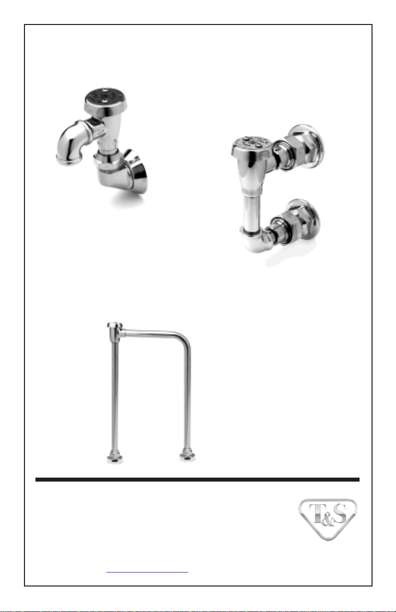
B-0965
Atmospheric Vacuum
Breaker Assembly
with Exposed Outlet B-0929
Atmospheric Back
Flow Preventer
B-0456
Atmospheric
Vacuum Breaker
Assembly
RELATED T&S BRASS PRODUCT LINE
Other manuals for B-0968
2
This manual suits for next models
1
Table of contents
Languages:
Other T&S Industrial Equipment manuals

Popular Industrial Equipment manuals by other brands


ITW Trans Tech
ITW Trans Tech Orion 130 Operator's manual

AIXTRON
AIXTRON CRIUS II System manual

ABB
ABB HT613215 Operation manual

AFL Hyperscale
AFL Hyperscale U Series installation guide

Bruderer
Bruderer BBV 190 Series Adjustment manual

Swann
Swann Flexcon In-Well Installation, Warnings, and Operation Instructions