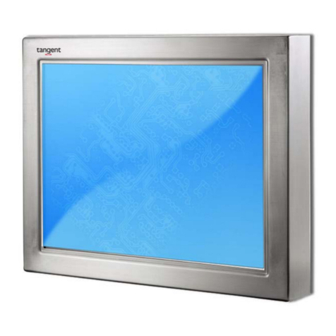
Tangent Medix KW User manual


Copyright2012
AllRightsReserved
ManualVersion1.2
Theinformationcontainedinthisdocumentissubjecttochangewithoutnotice.Wemakenowarrantyof
anykindwithregardtothismaterial,including,butnotlimitedto,theimpliedwarrantiesofmerchantability
andfitnessforaparticularpurpose.Weshallnotbeliableforerrorscontainedhereinorforincidentalor
consequentialdamagesinconnectionwiththefurnishing,performance,oruseofthismaterial.
Thisdocumentcontainsproprietaryinformationthatisprotectedbycopyright.Allrightsarereserved.No
partofthisdocumentmaybephotocopied,reproducedortranslatedtoanotherlanguagewithouttheprior
writtenconsentofthemanufacturer.
TRADEMARK
Intel®,Pentium®andMMXareregisteredtrademarksofIntel®Corporation.
Microsoft®andWindows®areregisteredtrademarksofMicrosoftCorporation.
Othertrademarksmentionedhereinarethepropertyoftheirrespectiveowners.
Safety
IMPORTANTSAFETYINSTRUCTIONS
1.Todisconnectthemachinefromtheelectricalpowersupply,turnoffthepowerswitchandremovethe
powercordplugfromthewallsocket.Thewallsocketmustbeeasilyaccessibleandincloseproximitytothe
machine.
2.Readtheseinstructionscarefully.Savetheseinstructionsforfuturereference.
3.Followallwarningsandinstructionsmarkedontheproduct.
4.Donotusethisproductnearwater.
5.Donotplacethisproductonanunstablecart,stand,ortable.Theproductmayfall,causingserious
damagetotheproduct.
6.Slotsandopeningsinthecabinetandthebackorbottomareprovidedforventilationtoensurereliable
operationoftheproductandtoprotectitfromoverheating.Theseopeningsmustnotbeblockedor
covered.Theopeningsshouldneverbeblockedbyplacingtheproductonabed,sofa,rug,orother
similarsurface.Thisproductshouldneverbeplacednearoroveraradiatororheatregisterorinabuilt‐in
installationunlessproperventilationisprovided.
7.Thisproductshouldbeoperatedfromthetypeofpowerindicatedonthemarkinglabel.Ifyouarenot
sureofthetypeofpoweravailable,consultyourdealerorlocalpowercompany.
8.Donotallowanythingtorestonthepowercord.Donotlocatethisproductwherepersonswillwalkon
thecord.
9.Neverpushobjectsofanykindintothisproductthroughcabinetslotsastheymaytouchdangerous
voltagepointsorshortoutpartsthatcouldresultinafireorelectricshock.Neverspillliquidofanykindon
theproduct.
1

CEMARK
ThisdevicecomplieswiththerequirementsoftheEECdirective2004/108/ECwith
regardto“Electromagneticcompatibility”and2006/95/EC“LowVoltageDirective”.
FCC
Thisdevicecomplieswithpart15oftheFCCrules.Operationissubjecttothe
followingtwoconditions:
(1)Thisdevicemaynotcauseharmfulinterference.
(2)Thisdevicemustacceptanyinterferencereceived,includinginterferencethatmaycauseundesired
operation.
CAUTIONONLITHIUMBATTERIES
Thereisadangerofexplosionifthebatteryisreplacedincorrectly.Replaceonlywiththesameorequivalent
typerecommendedbythemanufacturer.Discardusedbatteriesaccordingtothemanufacturer’s
instructions.
BatteryCaution
Riskofexplosionifbatteryisreplacedbyanincorrecttype.Disposeofusedbattery
accordingtothelocaldisposalinstructions.
SafetyCaution
Note:TocomplywithIEC60950‐1Clause2.5(limitedpowersources,L.P.S)related
legislation,peripheralsshallbe4.7.3.2“Materialsforfireenclosure”compliant.
4.7.3.2Materialsforfireenclosures
ForMOVABLEEQUIPMENThavingatotalmassnotexceeding18kg,thematerialofaFIRE
ENCLOSURE,inthethinnestsignificantwallthicknessused,shallbeofV‐1CLASSMATERIALorshall
passthetestofClauseA.2.
ForMOVABLEEQUIPMENThavingatotalmassexceeding18kgandforallSTATIONARY
EQUIPMENT,thematerialofaFIREENCLOSURE,inthethinnestsignificantwallthicknessused,shall
beof5VBCLASSMATERIALorshallpassthetestofClauseA.1
2

LEGISLATIONANDWEEESYMBOL
2002/96/ECWasteElectricalandElectronicEquipmentDirectiveonthetreatment,collection,
recyclinganddisposalofelectricandelectronicdevicesandtheircomponents.
Thecrosseddustbinsymbolonthedevicemeansthatitshouldnotbedisposedofwithother
householdwastesattheendofitsworkinglife.Instead,thedeviceshouldbetakentothewaste
collectioncentersforactivationofthetreatment,collection,recyclinganddisposalprocedure.
Topreventpossibleharmtotheenvironmentorhumanhealthfromuncontrolledwastedisposal,
pleaseseparatethisfromothertypesofwastesandrecycleitresponsiblytopromotethe
sustainablereuseofmaterialresources.
Householdusersshouldcontacteitherthemanufacturer,ortheirlocalgovernmentofficefor
detailsofwhereandhowtheycantakethisitemforenvironmentallysaferecycling.
Businessusersshouldcontacttheirsupplierandcheckthetermsandconditionsofthepurchase
contract.
Thisproductshouldnotbemixedwithothercommercialwastesfordisposal.
3

TableofContents
1.PackingList.................................1
1‐1.StandardItems........................................................1
1‐2.OptionalItems.........................................................2
2.SystemView...............................3
2‐1.Front&SideView....................................................3
2‐2.RearView................................................................3
2‐3.I/Oview..................................................................4
2‐4.Dimensions..............................................................5
2‐4‐1.15.6"System.............................................................................5
2‐4‐2.18.5"System.............................................................................5
2‐4‐3.21.5"System.............................................................................5
3.SystemAssembly........................6
3‐1.OpentheChassisCover...........................................6
3‐2.RAMModuleReplacement......................................7
3‐3.HDDReplacement...................................................8
4.PeripheralInstallation.................9
4‐1.MSRInstallation......................................................9
4‐2.CashDrawerInstallation........................................10
5.Specification...............................12
4

6.JumperSetting..........................16
6‐1.C48Motherboard....................................................16
6‐1‐1.MotherboardLayout............................................16
6‐1‐2.Connectors&Functions.......................................18
6‐1‐3.Jumper&BIOS/UtilitySetting..............................19
6‐2.C68Motherboard....................................................25
6‐2‐1.MotherboardLayout............................................25
6‐2‐2.Connectors&Functions.......................................26
6‐2‐3.JumperSetting.....................................................27
5

Thepageisintentionallyleftblank.
6

1.PackingList
1‐1.StandardItems
Note:Powercordwillbesupplieddifferentlyaccordingtoregionorcountry.
7
System Poweradapter
Driverbank Powercord
Usermanual
RJ45‐DB9cable(x2)
Allenwrench

1‐2.OptionalItems
MSR
8

2.SystemView
2‐1.Front&SideView
1. TouchScreen 3.Ventilation
2. Built‐inWebCam 4.MSRCableHole
2‐2.RearView
5.VESAMountingHoles
6.SafetyLabel
7. CableCover9

2‐3.I/OView
AtomMotherboard
10
ItemNo. Description
a
DCIN
b
LAN
c
CashDrawer
d
MICIN
e
LineOut
f
COMPort1,2,3,4(fromlefttoright)
g
USB(x4)
h
Printer
i
PowerButton
j
VGA
k
HDD5V
l
SATA(e‐SATA)
m
HDDslot

SandyBridgeMotherboard
11
ItemNo. Description
a
MICIN
b
DCIN
c
LAN(x2)
d
CashDrawer
e
LineOut
f
COMPort1,2,3,4(fromlefttoright)
g
USB(x4)
h
Printer
i
PowerButton
j
VGA
k
HDDslot

2‐4Dimensions
2‐4‐1.15.6"System
2‐4‐2.18.5"System
2‐4‐3.21.5"System
12

3.SystemAssembly
3‐1.OpentheChassisCover
ThemotherboardandRAMmodulecanbereplacedbyopeningthechassiscover,whichis
locatedonthebacksideofthesystem.Pleasefollowthestepsbelowtoopenthechassis
cover.
1. Turntothebacksideofthesystem
andloosenthethumbscrews(x2)to
releasethecablecoverfirst.
2. Loosenthehexsocketcapscrews(x8)
toopenthebackcoverofthesystem.
*
PleaseuseanAllenwrenchtotighten/loosenthe
screws.
13

3‐2.RAMModuleReplacement
ToremoveandreplacetheRAMmodule,pleasefirstopenthechassiscoverpersteps
describedinchapter3‐1.
RemovingaRAMmodule
1. Findthememoryslotattherightsideofthemotherboard.
AtomMotherboard
SandyBridgeMotherboard
2.Fliptheejectorclipsoutwards
toremovethememorymodule
fromthememoryslot.
InstallingaRAMmodule
3.Slidethememorymoduleinto
thememoryslotandpress
downuntiltheejectorclips
snapsinplace.
14

3‐3.HDDReplacement
ToremoveandreplacetheHDD,pleasefirstopenthecablecoverpersteps
describedinchapter3‐1‐1.
1.FindtheHDDlocatedattheright
side.
2.PulltheHDDtrayfromthesystem.
Foreasierremovalpullthe
plasticsheet(seepicture)atthe
sametime.
3.AttachtheHDDtotheHDDtray
andslideitintotheslotuntilit
snapsinplace.
*PleasenotethetopoftheHDD
shouldbeontheupperside.
15

4.PeripheralInstallation
4‐1.MSRInstallation
ToinstallMSR,pleaseopenthecablecoverfirstperstepsdescribedinchapter3‐1‐1.
1.InsertMSRmoduleinplaceand
fastenthescrews(x2)onthebackto
securethemodule.
2.ConnectMSRcabletotheconnector
onsystemside.
3.Closethecablecoverandfasten
screws(x2).MakesuretheMSR
cableisthreadedthroughtheMSR
cableholeonthesystem.
16

4‐2.CashDrawerInstallation
Youcaninstallacashdrawerthroughthecashdrawerport.Pleaseverifythepinassignmentbefore
installation.
CashDrawerPinAssignment
61
CashDrawerControllerRegister
TheCashDrawerControlleruseoneI/OaddressestocontroltheCashDrawer.
RegisterLocation:48Ch
Attribute:Read/Write
Size:8bit
BITBIT7BIT6 BIT5 BIT4 BIT3 BIT2BIT1BIT0
AttributeReservedRead Reserved Write Reserved
76543210
Reserved
CashDrawer“DOUTbit0”pinoutputcontrol
CashDrawer“DOUTbit1”pinoutputcontrol
Reserved
CashDrawer“DINbit0”pininputstatus
Reserved17
PinSignal
1GND
2DOUTbit0
3DINbit0
412V/19V
5DOUTbit1
6GND

Bit7:Reserved
Bit6:CashDrawer“DINbit0”pininputstatus.
=1:theCashDrawerclosedornoCashDrawer
=0:theCashDraweropened
Bit5:Reserved
Bit4:Reserved
Bit3:CashDrawer“DOUTbit1”pinoutputcontrol.
=1:OpeningtheCashDrawer
=0:AllowclosetheCashDrawer
Bit2:CashDrawer“DOUTbit0”pinoutputcontrol.
=1:OpeningtheCashDrawer
=0:AllowclosetheCashDrawer
Bit1:Reserved
Bit0:Reserved
Note:PleasefollowtheCashDrawercontrolsignaldesigntocontroltheCashDrawer.
CashDrawerControlCommandExample
UseDebug.EXEprogramunderDOSorWindows98
CommandCashDrawer
O48C04Opening
O48C00Allowtoclose
►SettheI/Oaddress48Chbit2=1foropeningCashDrawerby“DOUTbit0”pincontrol.
►SettheI/Oaddress48Chbit2=0forallowcloseCashDrawer.
CommandCashDrawer
I48CCheckstatus
►TheI/Oaddress48Chbit6=1meantheCashDrawerisopenedornotexist.
►TheI/Oaddress48Chbit6=0meantheCashDrawerisclosed.
18

5.Specification
ModelNameVITAKW
MedixKW
MainboardAtomMotherboard
CPUIntelPineviewdualcoreD5251.8G
ChipsetIntelICH8M
SystemMemory2xDDR3SO‐DIMMslot,upto4GB
GraphicMemoryIntelGMA3150sharesystemmemoryupto256MB
LCD/TouchPanel
LCDSize15.6"LEDLCD 18.5"LEDLCD
Brightness250nits
MaximumResolution1366x768
TouchScreenTypeTrueflatresistivetouch/Trueflatprojectedcapacitivetouch
Storage
HDD2.5"SlimHDDbay,SATAHDD
Peripherals
WebCam(Build‐in)2MWebCam
WiFi(Optional)802.11b/g/nWLANcard
MSR‐rightside(Optional)3Track(USB)
Expansion
MiniPCI‐ESocket1
ExternalI/OPorts
USB2.04xUSBTypeA
SerialCOM4(RJ45type,COM1/COM2standardCOM,COM3/COM4with
+5V/+12Vpowerselection)
Parallel1xD‐sub25F
LAN(10/100/1000)1xRJ‐45
2ndVGA1xDB15F
CashDrawer1xRJ‐11(12Vor24V)
AudioJack1xMic‐in,1xLine‐out
DCJack1xLatchType(4pin)
e‐SATABlindHole
PowerButton1
ThermalSolution
ThermalSolutionFanless
Audio
Speaker2x2W
Power
PowerAdapterDC19V/90W
19
Table of contents
Other Tangent Touchscreen manuals
Popular Touchscreen manuals by other brands

Elo TouchSystems
Elo TouchSystems 1938L user guide

Tekvox
Tekvox Podium TCX10 installation guide
Cooper
Cooper iLumin Plus TSE55-B installation instructions
Xenarc
Xenarc 700TSU installation manual
Crestron
Crestron TSW-750 quick start guide
Critical Environment Technologies
Critical Environment Technologies Visio-3 General operation guide

Planar
Planar Helium PCT2785 user guide
SunBriteDS
SunBriteDS DS-4217TSL Operator's manual
Elo TouchSystems
Elo TouchSystems ET1724L-7SWR-1-NL, ET1724L-8SW user guide
Vimar
Vimar 21554 user manual
TechNexion
TechNexion TEP-1560-BSW quick start guide
Elo TouchSystems
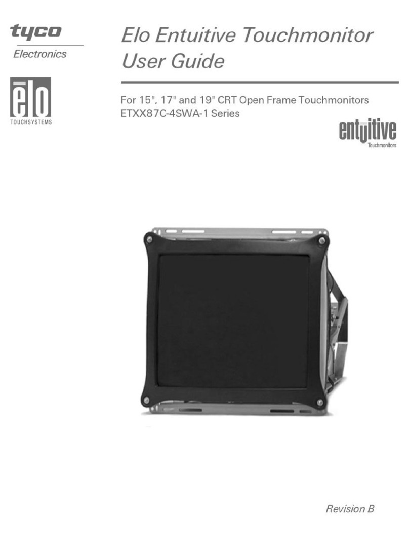
Elo TouchSystems ETXX87C-4SWA-1 Series user guide
