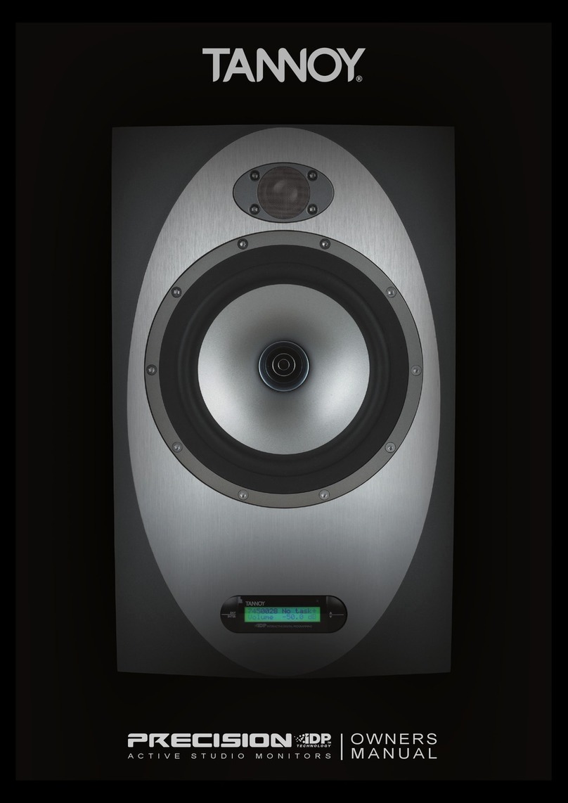
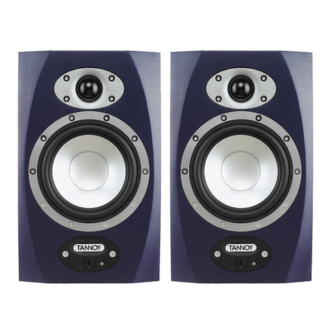
Tannoy ellipse PC/IP User manual

PC/IP Manual
Advanced Installers Package

1Introduction
2Installation
® Software installation and registration
3Initial system set-up
® Monitor task assignment
4Main display screen features
® Setup
® Levels & Gains
® Presets
} Bass Management
® Advanced Bass Management
5Function menu tasks
® Setup
} Reset
} Lock
} Backup
} Software
} Utility
6Monitor Parameters & EQ facilities
® Monitor Parameters
® Parametric EQ
} EQ Link
7Parameter categories
1Introduction
The enclosed disc contains the Tannoy iDPTM PC-iP installers software package; a comprehensive
editor & interface tool for the Ellipse iDPTM Monitor System.
The Ellipse PC-iP package allows parametric EQ facilities for specific room optimisation,
secure lockout of vital preset parameters and subwoofer delay adjustments.
All of these control functions are integral to the Ellipse iDPTM system; no external equalisers or
delay units are required. This makes the Ellipse PC-iP package an essential tool for the
Professional Studio sound system designer.
Once established using this comprehensive installation software, all system parameters are
controllable via the LCD display on the Master Ellipse monitors, Tannoy iDP SOFTTM or the
Ellipse iDPTM PC-iP package itself.
This manual acts as an operation guide for the Ellipse iDP PC-iPTM installer’s software package
only. A comprehensive system set-up guide, containing detailed parameter descriptions
and background information, can be found in the Ellipse iDPTM users manual packaged with
the monitors.
Connecting the Ellipse iDPTM monitor system correctly is essential; therefore please refer to the
Ellipse iDPTM users manual before going any further.
CONTENTS
3

2Installation
Computer system requirements
Windows 95,98,2000 or XP
Pentium 233 MHz
Minimum 16 MB of RAM
10MB free disk space
800 x 600 resolution with minimum 24-bit colour
One free Serial port (or USB - requires converter)
IMPORTANT
Connect only a single Tannoy Ellipse PC-iP software package to your Ellipse IDPTM network at
one time. If several connections are made simultaneously (from multiple PC's or ports) then the network
system functions will not work as intended.
Connection
The CAT-5 cable, supplied with the installation software package, has a CAT-5 plug at one end and
a serial plug at the other and must be connected as follows:
To any Ellipse iDPTM monitor in the network
Connect the Cat-5 plug to the TC LINK socket to be found on the rear panel of the
Ellipse iDPTM monitor.
To computer Serial port
Connect the Serial plug to a free Serial port on your PC.
To computer USB port
Alternatively you can connect via a USB port by using an optional
"USB to Serial Port" converter.
Installing the software from the Ellipse PC-iP CD
} Exit all running programs.
} Place the CD in your CD ROM drive.
} Open the CD contents.
} Press <Setup> - the guide begins.
} Read warning and press <Next>.
} The set-up guide suggests a location on your C drive where the program will be installed.
Press <Next> to confirm the destination folder or change the destination folder before
pressing <Next> again.
} The software will be installed on your computer.
} Enter Registration key, serial number and additional information and press <OK>.
}A window opens holding a shortcut for the Ellipse PC-iP program. Copy this shortcut to your
desktop to allow convenient launch of the PC-iP installer program in future.
INSTALLATION
4
Registration key
The registration key is supplied along with the Ellipse PC-iP software package. Later updates to the
software will not require the registration key as long as these updates are installed on the same PC.
Start
Launch the program. The program will try to detect any Ellipse iDPTM system connected to the computer
COM ports.
If no monitors are connected, or the system is wired incorrectly, an error message will appear – see
Fig. 1.
Fig.1. Network error - system not found message
To rectify the problem please refer to the user manual for the correct connection details.
5

3 Initial system set-up
The first screen to appear once program has fully launched, with all the networked monitors and
subwoofers recognised, is shown in Fig. 2. The network is displayed in the set-up section on the left
side of the screen.
Fig.2. Initial system set-up screen change to blank layout sketch
Monitor task assignment
Each Ellipse IDPTM monitor must be assigned a given task so that the network recognises where each
monitor is placed in the system. From the horizontal row of buttons in the <Functions> menus select
<Setup>. On the window that appears open the drop down menu <Ellipse setup> and select the type
of system configuration you are installing.
The choices from this menu are:
- Empty
- Stereo
- Surround
*Optional 192kHz, Dual Wire, Digital Input Card required.
If required check the <BNC Sync> box for locking on the BNC input.
6

Monitor task assignment /cont.
Fig.3. Monitor setup window.
Then proceed to set the monitor tasks by selecting one of the Ellipse models in the serial numbers list
(see Fig 3) where you will see that each monitor & subwoofer has its own unique serial number.
Check the <Pink Noise> box to activate the pink noise generator in the selected monitor. Select the
monitor task matching the position of the monitor reproducing the pink noise before un-checking the
<Pink Noise> box. Repeat this process for all of the other connected monitors and subwoofers. There
is no need to press the <Exit> button until all of the monitors have been assigned their respective tasks.
Having assigned the tasks the main display window will show all the connected monitors and subwoofers
with their serial numbers showing in their correct location in the system layout graphic.
7

4. Main display screen features
Fig.4. Main display screen
With the tasks now assigned to the monitors and subwoofers the individual speaker serial number and
its location is displayed within the setup section of the main screen.
The layout and description of all of the functions displayed on this main screen can be split up into
the following subsections:
Setup section
<M> Mute function for each monitor
<S> Solo function for each monitor
<Edit> This drop down menu holds all of the detected monitors on the network, all with
their own unique serial numbers. Select each monitor individually and press edit
to set the parameters for each Ellipse IDPTM monitor or Subwoofer (see the ‘EQ
facilities’ section of this manual)
8

Software license info
<Ref. Levels>
Mouse click on the Ellipse <icon> on the blue header bar at the top left of the
main display screen to view the software license information and version.
Levels & Gain section
<Ref. Levels>
There are three reference levels that can be preset by the user. Select one of the
three ‘Ref. Levels’ and set the master volume fader to suit. The setting is then
stored instantly. Repeat the process for the other two ‘Ref. Levels’. When ‘use fader’
is selected the master volume fader is used for adjusting the overall level.
<A-Sensitivity>
This is the Analogue Input sensitivity.
Select the analogue sensitivity (+9, +15, +21 or +27dBu) to match the gain
range of the mixing console or source equipment, which is feeding the
Ellipse IDPTM monitors.
<Mute All>
This button mutes all or the monitors on the network.
<Clear Solo>
This button releases the monitors from solo mode.
<Master Volume>
This is the master gain control for the connected system relative to the set
reference level. The reference level for each monitor is set by using the <Edit>
button or by double clicking on each respective monitor in the setup section of
the screen.
Preset section
<Drop down list>
This drop down menu displays the full list of user and factory presets for
direct access
<Recall>
When pressed this button recalls a preset from the drop down menu.
Simply highlight the preset you wish to recall and hit the ‘recall’ button.
<Store>
Press ‘store’ to save a preset. User presets can be stored in locations 1 –15.
Presets 16 – 32 are factory set presets cannot be edited.
<Note>When pressed, this button allows you to change the preset name and edit any
previous personal notes. The <Note> function can only be used on the user
presets (1 –15)
9

Bass Management section
<Factory pre-sets>
This part of the Ellipse PC-iP software allows the user to set the desired
Bass Management crossover frequency. There are seven factory set management
options that can be selected by checking the box beside the desired frequency.
For further adjustment flexibility you may choose to activate the advanced bass
management function by checking the <on> box. The seven preset Bass Management
settings shown can now no longer be selected.
The <Advanced> button can then be activated to take you into the
Advanced Bass Management section.
Advanced Bass Management
<Advanced>
To activate the advanced bass management and access the set-up window
(see fig.5) check the <On> box in the Bass Management section of the main screen,
then press the <Advanced> button.
Fig.5. Advanced bass management window
<Satellite HP Filter>
This is an independent Hi pass filter for the Ellipse monitors.
This can be combined with both 4th order and/or 2nd order Low Pass
subwoofer filters.
One or both of the Subwoofer low pass filters can be activated. If both are activated
then you are effectively cascading both filters (6th order)
<LFE=Sub>
By checking this box the LFE filter is set equal to the Subwoofer filter thus avoiding
phase cancellation. When activated, the coefficients from the two sub filters will be
copied to the LFE filter.
The sub filter in the EQ section can still be activated on top of the <LFE=Sub>
filter setting.
10

5. Function menu tasks
The horizontal row of six buttons in the Function section of the main screen perform the following tasks:
<Setup>
This operation of the setup function is to open the <Ellipse setup> window to allow
selection of the monitor configuration being installed and to assign tasks to each
component in that system.
The actions involved are fully described in section 3 of this manual – Initial
System Setup.
<Reset>
Press this button to access the <Reset> menu shown in Fig. 6 in which three main
functions can be accessed.
Fig.6. Reset function menu
<Clear Setup for Network>
This reset procedure clears all of the network settings (both the monitor tasks
and setup)
<Clear Monitor Settings>
All stored global and local parameters in the connected monitors are reset.
Presets and network settings will not be affected.
<Factory Reset>
This reset procedure will delete all global and local parameter settings as well
as preset and network settings.
11

<Lock>Press this button to access the <Lock> menu as shown in Fig 7. The purpose of
this menu is to prevent accidental change of important parameters, which have
been previously set up.
Fig.7. Lock function menu
The lock function can be applied to the following areas – Global Parameters, Local Monitor Parameters,
& User Presets. Simply select a parameter you wish to lock from the list and check the ‘locked’ box in
each case to lock the desired parameter. A specific selection or all parameters may be locked.
A locked parameter will show [Lck] next to its list entry.
The following parameters can be locked:
Global Parameters Reference levels 1,2 &3
Store Presets
Recall Presets
Local Monitor Parameters Delay
Calibration Levels
Bass
Treble
Speaker Room Position
Phase (Subwoofer)
LFE Polarity
User Presets User Presets 1-14
Use the lock function to avoid the user presets
being accidentally overwritten.
<Clear All> This button will clear all locked parameters.
<OK> Confirm locked parameters and return to main screen.
12

<Cancel>
This will exit the ‘parameter & preset lock’ window and return you to the
main screen. No changes to the lock settings will be saved.
<Backup>
Press this button to access the <Backup> menu shown in Fig 8. This allows you
to create a backup file of your setting at a specified location on your computer.
Fig.8. Backup function menu
Backup files contain all local and global parameter settings but NOT monitor tasks
and presets.
- The parametric EQ settings are stored locally in the Ellipse iDPTM monitors with
each preset.
- Recalling any preset will recall the parametric EQ settings stored along with that
particular preset.
- However, the EQ graph in the parametric EQ screen will always display the
EQ settings of the most recently recalled backup file.
N.B. This may not be the EQ graph matching the current preset.
We therefore recommend that you carry out the following procedure when and if
changing parametric EQ settings between presets in the Ellipse iDPTM PC-iP software:
-Create a backup file using the Backup feature for every preset that has modified
parametric EQ settings.
- Recall presets that have different EQ settings via the Backup menu.
This ensures that the Parametric EQ graph matches the currently recalled preset.
You must be connected to the monitors to use the Backup facility as the data is read
from the monitors – a backup cannot be made when the software is in demo mode.
To locate a saved Backup file - write the path, browse or select a previously used
path from the drop down list in the Backup menu.
!
13

<Backup> /cont.
<Read Note>
Allows access to any user notes attached to the current preset.
<New Note>
This allows you to enter new note text for the current preset.
<View>
This lets you view all parameters and settings for the current preset.
<Recall>
Recall the backup file at the selected location.
<Software> Press to access the <Software Loader> menu shown in Fig 9.
Fig.9. Software update loading menu
It may be the case that new software and firmware features become available in
the future. A software loader feature is available to allow you to keep up with the
latest developments and updates without having to purchase new hardware.
Loading new monitor software using the Ellipse iDPTM PC-iP software
1. Place the new software at a convenient place on your hard drive. If the software has
been downloaded in the form of a zip file, then you will have to extract the file first.
2. Select the Communications (Com) Port you wish to use for the download.
3. In order to be able to download new software the Ellipse iDPTM monitors have to be
set to Boot mode. Checking the <Restart to Boot before Transfer> box does this.
4. Use the drop down menu <File locations & software type> and browse for the
file to be downloaded.
5. Select the desired file and press the <Send file> button to upload the new software
onto the Ellipse iDPTM Monitors.
14

<Update single monitor not in network>
Check this box if you are updating one monitor at a time or if the monitors are not
connected to the network.
<File information>
This button allows you to read the file information on the software that you select
in the drop down menu.
<Read Version>
This allows you to see the current software loaded on your Ellipse iDPTM monitors.
<Exit> This allows you to exit the Monitor Software Loader window and return to the
main page.
<Icon>The Ellipse icon on the blue header bar at top left of the window can be pressed
to view the software license information and version.
<Utility>
Press this button in the function menu to access the <Utility> menu shown in
Fig 10.
Fig.10. Utilities menu
<Standby Mode>
The purpose of standby mode is to offer power saving options.
15min
30min
1hr
1.5hrs
Off
Select a time after which you wish your Ellipse iDPTM monitors to go into
standby mode. If the monitors detect no signal within the predetermined time period
then they will go into standby mode. Normal operation will resume when an input
signal is detected.
15

<Sleep Mode>
To further minimize power consumption when the monitors are not in use,
Sleep mode can be used. The sleep mode options are -1hr, 1.5hrs, 2.5hrs, 3hrs
& 5hrs. To resume normal operation a command must be sent to the
<Sleep Mode> /cont.
system, for example, a master volume change or preset recall. This can be any
command sent via the master display of any master monitor on the network, the
remote, iDP SOFTTM or the PC-iP software.
<Backlight>
Three modes of operation can be set for the backlight display on the master
Ellipse monitors.
On
The display backlight will stay on unless the sleep mode function is activated.
Auto
The display backlight will light when any of the LCD keys are touched on
the monitors. The backlight will also light when the monitors are activated from
the ‘Standby’ or ‘Sleep’ states.
Off
The display backlight is always off.
<Store Master Volume>
When this box is checked the current master volume setting will be stored when
Standby or Sleep modes takes effect.
If the box is not checked then the system will revert to –50dB(default) when the
monitors are reactivated.
16

6. Monitor Parameters & EQ Facilities
Monitor Parameters
In order to access the Monitor parameters & EQ facilities page, see Fig. 11; click once on any monitor
on the network in the main page you would like to EQ or select a monitor from the drop down menu
and press the <Edit> button.
Fig.11. Monitor parameters window
The monitor parameters that may be adjusted in this window are:
<Polarity 180 deg>
This function is only available on the subwoofer. Check the box to reverse the polarity
of the subwoofer.
<Lck > This facility disables the Polarity 180 deg option in case of accidental activation.
If locked the no alteration is possible from the master monitor or iDP SOFTTM.
<LFE> Mark this box to activate the Low pass filter. Again this function is only available
on the subwoofer.
<Room Position>
Assuming that no RTA measurement system is being used you can set the position
in the room of each respective monitor using the drop down menu. There is an
<Lck> (Lock) facility to disable the room position facility in case of
accidental activation. If locked the no alteration is possible from the master monitor
or iDP SOFTTM.
The monitor room positions available for selection are:
Neutral – freestanding away from boundaries
Wall – against a wall i.e. one boundary
Corner – in a corner i.e. two boundaries
Console – located above console in very close proximity
Console Wall – above console against a wall
Console Corner – above console in corner
17

Monitor Parameters /cont.
<Test Signals>
Check the pink noise box to send pink noise the selected monitor.
When the ‘96kHz EQ’ out box is activated the Link 2 connection on the
Ellipse I=iDPTM set as the system controller will send out the signal after the
EQ section.
The function of this facility is only for measuring purposes. The output format is
AES/EBU at double the sample rate of the digital input. If an analogue input signal
is used the signal is up converted to 96kHz.
<X-Curve>
From the drop down menu you can select between:
Off
X-curve1
X-curve2
When the Parametric EQ facility is activated the x-curve facility cannot be activated.
A full description of the X-Curve functionality can be found in the Ellipse iDPTM
user manual.
<Mute>
Check this box to mute the selected monitor.
<EQ On>
Check this box to activate the Param.EQ button
<Exit>
Press this button to return to the main screen
<Delay>
The delay time on the selected monitor can be adjusted using the fader in the
range of 0 to 1.75m (68.9”). This allows alignment of the monitors to comply with
ITU standards.
There is a <Lck> (Lock) facility to disable the ‘delay’ facility in case of accidental
activation. If locked the no alteration is possible from the master monitor or
iDP SOFTTM.
<Calib.Lev>
The calibration level on the selected monitor can be adjusted using the fader.
This is an individual calibration level for each monitor in the range of –6dB to +6dB.
There is a <Lck> (Lock) facility to disable the ‘Calib.Lev.’ in case of
accidental activation. If locked the no alteration is possible from the master monitor
or iDP SOFTTM.
<Rel.Lev>
The relative level on the selected monitor can be adjusted using the fader. This is
the preset volume for the selected monitor relative to the calibrated levels and the
master volume. The Range is –40dB to 0dB.
18

Monitor Parameters /cont.
<LFE Gain>
This function is only available on the subwoofers. The fader can be used to boost
or cut the gain of the LFE channel in the range of -6 to +8dB.
<Phase>
This function is only available on the subwoofers. The fader can be used to adjust
the phase (time alignment) if the Subwoofer cannot be placed in an
optimum position. There are individual phase settings for each of the Bass Management
crossover frequencies. When set, these are stored as Global settings.
<Equalize>
The faders can be used to adjust the bass & treble for the selected monitors in
the range of -6 to +8dB. The Equalize parameters are only active when the parametric
EQ function is inactive.
There is a <Lck> (Lock) facility to disable the ‘equalize’ facility in case of
accidental activation. If locked the no alteration is possible from the master monitor
or iDP SOFTTM.
Parametric EQ
To access the Parametric EQ page:
In the Main page click on the monitor you would like to EQ or select a monitor from
the drop-down menu and press the <Edit> button.
You are now in the Monitor page.
Check the <EQ on> box and press the <Param.EQ> button to enter the
Parametric EQ window as displayed in Fig. 12.
Fig.12. Monitor parameters and
Parametric EQ windows.
19

Parametric EQ /cont.
There are four user definable EQ sections that can be edited
If EQ is required, select the EQ type for each band via the drop-down menus in each
EQ section. See Fig. 13.
Options:
Band Off
Parametric
Low Shelve
High Shelve
Low Pass
High Pass
GainRange: -12dB to 12dB – Adds or subtracts gain for the selected band.
Freq.Range: 25Hz to 20kHz – Sets the target frequency for the band.
S/BW
Sets the Slope or Bandwidth depending on the selected EQ typ
A single band EQ is available for the Subwoofer channel:
Fig.13. Sub bass EQ window and parametric
IMPORTANT
The Ellipse iDPTM loudspeakers are designed to need no equalization or correction to overcome
system limitations. As a result, they will only need equalization to compensate for difficult
acoustic environments or unusual room placement.
Over equalization can reduce system headroom, and introduce phase distortion resulting
in greater problems than cures. If equalization is required then it should be applied gently
and smoothly. Ellipse iDPTM Monitors are point source; phase coherent designs in fact,
so violent equalization will be detrimental to the overall sound quality.
20

REMEMBER - The parametric EQ settings are stored locally in the Ellipse iDPTM monitors with
each preset.
- Recalling any preset will recall the parametric EQ settings stored along with that
particular preset.
- However, the EQ graph in the parametric EQ screen will always display the
EQ settings of the most recently recalled backup file.
Not necessarily showing the EQ graph matching the current preset.
See the <Backup> function.
EQ Link
Press this button in the Monitor Equalizer menu to access the <EQ Link> menu as shown in Fig.14.
Fig.14. EQ Link menu
Creating EQ groups can save time. For example, in the 6.1 system configuration shown in Fig. 14,
the Left front, Centre and Right monitors are grouped together. The Left surround, Centre surround
and Right surround monitors are also linked together into another group.
After grouping the monitors together in this way, any EQ applied to one of the monitors in a common
group will be copied to the others in that same linked group. Be sure to link the monitors into groups
before you apply EQ.
Add or remove monitors to the three groups by highlighting the monitor and assigning it to its respective
group by pressing the <Add G1/2/3> button. Activate or deactivate by checking or un-checking the
<G1-G3 Active> button.
!
21
Table of contents
Other Tannoy Speakers manuals

Tannoy
Tannoy PCI 7DC IW User manual

Tannoy
Tannoy ProtoJ User manual

Tannoy
Tannoy MERCURY F1 User manual

Tannoy
Tannoy CMS801 DC BM User manual

Tannoy
Tannoy V300 User manual

Tannoy
Tannoy DVS Series User manual

Tannoy
Tannoy QFLEX 16LS-WP User manual

Tannoy
Tannoy V12HP User manual

Tannoy
Tannoy DUAL CONCENTRIC ic6 DC User manual

Tannoy
Tannoy i7 T User manual

Tannoy
Tannoy Reveal 5A User manual

Tannoy
Tannoy CVS Series User manual

Tannoy
Tannoy VLS SERIES User manual

Tannoy
Tannoy CMS60 ICT-30 User manual

Tannoy
Tannoy Definition Install DC6i User manual

Tannoy
Tannoy 623 Configuration guide

Tannoy
Tannoy iw4DC User manual

Tannoy
Tannoy i8 AW User manual

Tannoy
Tannoy i15 User manual

Tannoy
Tannoy VLS SERIES User manual