Tannoy DIMENSION TD10 User manual

DIMENSION TD10
SERVICE MANUAL

Technical Manual Contents
•Introduction – The Technical Manual explained
Page 2
•Technical Specs – Specifications relating to this particular item.
Page 3
•Instructions – For faultfinding, assembly & disassembly.
Page 4
•Spares Drawing – All spare parts available to order for your
loudspeaker as well as additional spares including the likes of spikes &
feet.
Page 5
•Returns – Our field failure process explained and FFR returns form.
Page 7
•Warranty – Warranty information with contact info.
Page 11
Page 1

Technical Manual Explained
This Manual is designed to help you and your customers. In this manual you
will find all information you will need regarding service to your Tannoy
loudspeaker including technical specs, instructions for assembly, disassembly
& faultfinding, spares drawings & parts lists as well as a detailed explanation
of how to go about returning parts under warranty.
For further information regarding service or spares ordering, please contact
us directly.
TANNOY UK
Tannoy Ltd.
Coatbridge, North Lanarkshire
ML5 4TF
Scotland, United Kingdom
T: 44 (0) 1236 420199
F: 44 (0) 1236 428230
E-mail: enquiries@tannoy.com
Page 2

Specifications
TD10
PERFORMANCE
Recommended amplifier po er 50 - 200 Watts RMS
Continuous po er handling 130 Watts RMS
Sensitivity (2.83Volts @ 1 metre) 91dB
Nominal impedance 6 Ohms
Frequency response 38Hz - 54kHz -6dB usable output to 100kHz
DRIVE UNITS
Dual Concentric™ high frequency 25mm (1.00") 50-micron aluminium dome ith Tulip
WaveGuide™
Dual Concentric™ lo frequency 250mm (10.00") paper pulp cone ith a t in roll
impregnated fabric surround
SuperT eeter™ 25mm (1.00") 25 micron titanium dome, ith neodymium
magnet system
Dispersion 90° conical
CROSSOVER
Frequency Dual Concentric™ 1.2 kHz
SuperT eeter™ 14 kHz
Type Dual Concentric™ Bi- ired, hard- ired passive, lo loss, 3rd order lo pass,
1st order high pass
SuperT eeter™ 3rd order high pass filter
CONSTRUCTION
Enclosure type T in port reflex
Volume 67 Litres
Dimensions 1015 x 350 x 370mm (40.00 x 13.80 x 14.60")
Additional features High-density 25mm (1.00") birch ply enclosure, internally
cross braced
Weight 32 kgs (70.5 lbs)
Finish American cherry ith polished alloy trim detail
Front baffle panel High-density 38mm (1.50") birch ply
Page 3

Fault Finding
Tannoy loudspeakers are designed and manufactured to be
reliable. When a fault occurs in a hi-fi system the effect is
always heard through the loudspeakers although they may
not be the source of the fault. It is important to trace the
cause of the problem as accurately as possible. A fault
heard on one source (only CD or tape for instance) is most
unlikely to be a loudspeaker problem. Loudspeakers do not
in themselves generate hum, hiss or rumble although high
quality, wide bandwidth loudspeakers may emphasise such
problems.
Page 4

Page 5

TD 10 RE-WORK
Tools Required:
3mm Hex Key, and 4mm Hex Key
Procedure:
Un-pack the product.
Remove front velvet panel, (Tee-bar through socket aperture Fig 1,2).
Remove driver and disconnect wires.
Remove trim ring and unscrew T/P panel – (should be able to locate loose screws
Re-attach crossover to centre brace – screwing screws into tech-serts in brace.
Replace wadding x 1, connect driver and secure.
Fit front velvet panel with screw x 6.
Fig 1 Fig 2
Remove front velvet panel screws, half turn each as per Fig 2 until loose.
Page 6

Field Failure Report Explained
This Procedure is designed to help you and your customers. By ensuring that we are supplied with full
details of all product failures, on the attached Field Failure Report, we can promptly assess the information
and rapidly implement remedial action. A further benefit is that we can use analysis of the data to identify
design improvements that maybe applicable to improve product reliability.
Method:
1. You - Fill in the complete product failure details on to the attached Field Failure Report template,
including product serial number, and then fax or e-mail to Tannoy Service Department. Fax: +44 (0)
1236 428230 or E-mail: service@tannoy.com
2. We - Will enter the information supplied to us onto our Field Failure Report database. And appropriate
action will be taken.
3. We - Cannot authorise the supply of spare parts free of charge, or under warranty, without complete
information as to the nature of the failure.
4. You - Are required to hold all parts for which warranty claims have been made until instructed otherwise
by Tannoy. We may require to inspect failed parts at a later date.
Important
Please note: When claiming spare parts under warranty the part will only be supplied free of charge if the
order is accompanied by a completed Field Failure Report.
Return of faulty or damaged complete product.
Please use the Tannoy Returns Authorization Request Procedure if you require to return complete faulty or
damaged product to Tannoy. Please contact the Tannoy Service Department for authorisation before
returning product.
Fax: +44 (0) 1236 428230 or E-mail: service@tannoy.com
Regards,
Gabriel O’Donohue
Gabriel O’Donohue
Customer Support Specialist
E-mail: Gabriel@tannoy.com
Tel: +44 (0) 1236 420199
Fax: +44 (0) 1236 428230
Page 7

Customer Complaint / Fault Report
Internal Use Only:
Warranty Decision: Source Area: Report No:
Customer Section:
Product Description: Part Number: Date:
Customer / Distributor: 20-Digit Product Barcode Number (MANDATORY):
Detailed description of problem/ fault (MANDATORY):
Insert pictures below:
Please be aware that we cannot accept field-failure reports that do not have mandatory sections
completed.
Page 8

FOR GUIDANCE
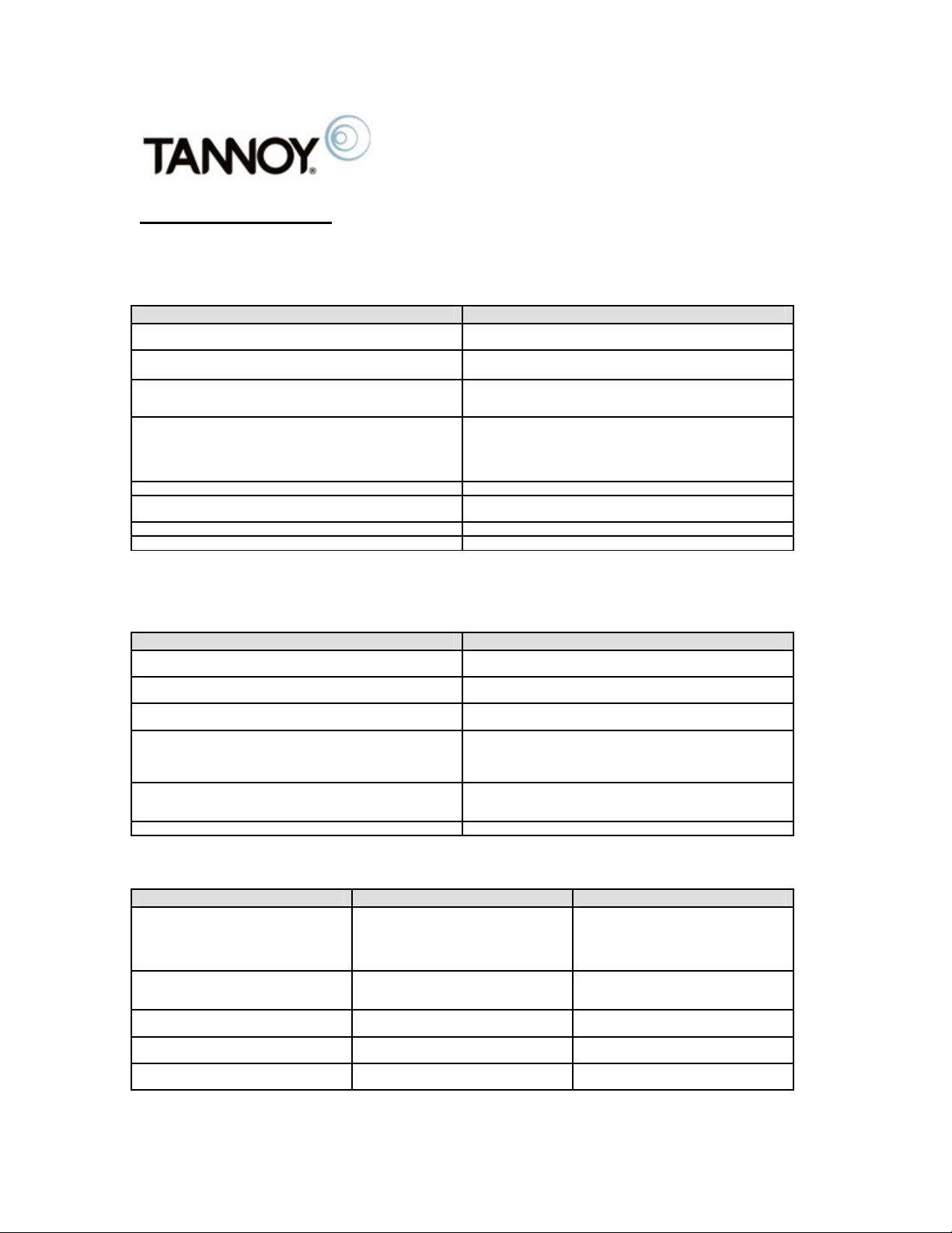
Diagnosis of low frequency driver failures resulting from
misuse:-
SYMPTOM PROBABLE CAUSE
Charred voice coil Under powered amplifier clipping; Excessive peak amplifier
power; DC at amp output (amp failure)
F u s e d , b r o k e n o r b l a c k e n e d l e a d o u t w i r e s
Under powered amplifier clipping; Excessive peak amplifier
power; Excessive low frequency equalisation applied
Voice coil out of gap
Excessive peak amplifier power; Excessive low frequency
equalisation applied
Coil rubbing
Excessive continuous amplifier power resulting in separation of
coil former from cone or suspension; Coil delamination due to
excessive temperatures generated; Improper mounting of driver
resulting in deformation of frame; Dropping of cabinet resulting in
deformation of frame or shifted pole piece
Broken frame or misaligned magnet assembly Dropping of cabinet ; careless transportation
Torn or punctured cone Excessive low frequency equalisation applied; Excessive peak
amplifier power; vandalism
Cone to coil joint failure Excessive low frequency equalisation applied
Suspension to coil/cone joint failure Excessive low frequency equalisation applied
Diagnosis of high frequency driver failures resulting
from misuse:-
SYMPTOM PROBABLE CAUSE
Charred voice coil Under powered amplifier clipping; Excessive peak amplifier
power; DC at amp output (amp failure)
Fused or broken leadout wires Excessive amplifier power; connection to low frequency or
midrange amplifier in active system
Leadout to coil joint failure (solder) Excessive amplifier power generating excessive temperatures
which melts solder >300°C
Coil rubbing Excessive continuous amplifier power resulting in separation of
coil former; Coil delamination due to excessive temperatures
generated; Improper replacement of diaphragm assembly;
Dropping of cabinet resulting shifted pole piece
Diaphragm cracked or pulverised Excessive continuous amplifier power (often frequency related);
Under powered amplifier clipping; Connection to low frequency
or midrange amplifier in active system.
Misaligned magnet assembly Dropping of cabinet ; careless transportation
Diagnosis of manufacturing defects:-
DEFECT TEST RESULT
Insufficient glue on:-
Cone to coil/suspension
Cone to surround
Surround to frame
Suspension to frame
Sine wave sweep
Buzzing sounds due to separation of
defective joints
Incomplete bonding of voice coil to
diaphragm or insufficient glue on rubber
surround to phase corrector joint
Sine wave sweep Buzzing sounds; Coil rubbing; Separation
of the coil from the diaphragm
Dry solder joints on leadouts DC resistance of voice coil termination Coil resistance greater than the rated
impedance, or open circuit
Faulty welds at the voice coil terminations
on the coil former
DC resistance of voice coil termination
Coil resistance infinite or intermittent
Poorly assembled driver Visual check
Sine wave sweep
Buzzing sounds; Loose parts; Coil
rubbing; foreign particles in magnetic gap
Page 9

Export Returns Authorization Procedure
Our returns system has been designed to help you and us by ensuring that product returned to
the factory is dealt with promptly and correctly.
No product should be returned without following this procedure.
What to do:
1. YOU - Contact the Tannoy Sales / Service Department with a request for a Returns
Authorization Number, stating the type of product, quantity of product to be returned and
reason for return.
2. WE- Quote you a Returns Authorization Number and send you an Export Returns
Authorization Form, by fax or e-mail.
3. YOU - Fill in all the relevant details in the form and send it to Tannoy, before arranging
shipment.
4. WE– On return of the completed form, we will send you written approval to return the goods.
5. YOU – Arrange despatch of the goods to us ensuring the Returns Authorization Number is
clearly quoted on all paperwork. (Please be sure to agree any shipping cost with Tannoy
BEFORE returning products)
Im p o rt an t
Authorization must be obtained, in writing from Tannoy, before any products are
returned. No responsibility will be accepted on our part for repair, replacement or
credit unless this authorization has been given.
Page 10

Warranty Policy
Tannoy loudspeakers are warranted against
manufacturing defects in material or
craftsmanship over a period of 5 years from the
date of purchase.
This warranty is in addition to your statutory rights as
a customer. Tannoy cannot however be held
responsible for failures caused by abuse,
unauthorised modifications, improper operations or
damage caused by faults elsewhere in your system.
Tannoy Ltd or its authorised Distributor or Service
Agent will make the determination of the cause of
failure based on physical inspection of the failed parts.
If you suspect a problem with your loudspeakers then
in the first instance discuss it with your Tannoy Dealer.
The Dealer has the expertise and experience to help
you troubleshoot the system and assess the situation.
If you continue to have problems contact your Tannoy
Distributor or Tannoy Customer Services at our
Coatbridge address. Due to our policy of continuous
improvement, all specifications are subject to change
without notice.
Page 11

NOTES
Page 12

NOTES
Page 13

Table of contents
Other Tannoy Speakers manuals

Tannoy
Tannoy i15 User manual

Tannoy
Tannoy ProtoJ User manual

Tannoy
Tannoy VLS 15 User manual

Tannoy
Tannoy Di6 DC User manual

Tannoy
Tannoy Power Dual iQ 10 User manual

Tannoy
Tannoy CMS6 TDC User manual

Tannoy
Tannoy V12HP User manual

Tannoy
Tannoy MERCURY V User manual

Tannoy
Tannoy SR601 User manual

Tannoy
Tannoy MERCURY Vi User manual

Tannoy
Tannoy QFLEX 64 User manual

Tannoy
Tannoy DVS Series User manual

Tannoy
Tannoy VQ 100 User manual

Tannoy
Tannoy VNET 12 User manual

Tannoy
Tannoy Ellipse 10 Passive User manual

Tannoy
Tannoy T12 User manual

Tannoy
Tannoy mercury 7 User manual

Tannoy
Tannoy AMS Series User manual

Tannoy
Tannoy V12HP User manual

Tannoy
Tannoy ST50 User manual