TAPKO MECps640 User guide

MECps
MECps640
KNX Line/Area Coupler/Repeater
with integrated 640 mA KNX Power Supply
Technical and Application Description

MECps
- 2 -
This document is property of the company named at the last page.
Without written approval, it may not be reproduced or commercialized,
distributed or presented to other individuals for commercial purpose.
Details and information contained within may be subject to change
without notice. For the accuracy of the document no warranty is given.
All rights reserved.

MECps
- 3 -
Content
1Product Description 4
1.1 Front Panel 5
1.2 LED Indication 6
1.3 LED Indication of Special Functions 7
1.4 Commissioning 8
1.5 Important Notes 9
1.5.1 Installation and Commissioning 9
1.5.2 Mounting and Safety 9
1.5.3 Maintenance 9
1.6 Feature Summary 10
2Operational Description 11
2.1 TP Coupler Application 11
2.2 TP Repeater Application 12
2.3 KNX Network Installation 13
2.3.1 Individual Address 13
2.3.2 KNX Topology 14
2.4 Programming 15
2.4.1 Programming Button 15
2.4.2 Individual Address Assignment 15
2.5 Special Functions 16
2.5.1 Manual Function 16
2.5.2 KNX Bus Reset 16
2.5.3 Factory Reset 17
3ETS Database Parameters Coupler 18
3.1 General 18
3.2 Main Line 19
3.3 Subline 21
4ETS Database Parameters Repeater 23
4.1 General 23
4.2 Main Line 24
4.3 Subline 25
5State of Delivery 26
5.1 Default Factory Settings 26
5.2 Technical Datasheet 27

Product Description
MECps
- 4 -
1Product Description
Having a very small footprint of only 2 units (36 mm), the combined KNX system device
MECps640 merges the functionalities of two different system devices. Additional to coupling
two TP lines and providing KNX line coupler functionality, MECps640 has an integrated KNX
Power Supply to generate a 640 mA output. With this choked output, the KNX TP Line that is
connected to MECps640 on secondary side (subline) is powered by a voltage of 30V DC.
MECps640 can be used as a line coupler, area coupler or line repeater.
To provide a bi-directional data connection between two KNX TP lines or areas, MECps640
works as a KNX line/area coupler in the KNX network. KNX TP main line and KNX TP subline
are coupled having a galvanic isolation in between. The choked output is overload-proof and
short circuit protected. Extended frames and long telegrams with up to 240 bytes APDU
length are supported. The LED display indicates states of the device and the bus lines. On
button press, the device can be reset. Also, the subline can be reset on button press.
Using the TP Coupler application, MECps640 can be used as KNX TP line coupler to connect
different TP Lines, Areas and Segments. Telegram filtering is accomplished according to the
installation place in the hierarchy (Physical[ly addressed] Telegrams) and according to the
built in filter tables for group communication (Group [oriented] Telegrams). For detailed
diagnosis, all operational modes/states are shown by a duo-LED display. Programming on
main line from the subline can be suppressed. Telegram repetition on both TP lines can be
reduced.
Using the TP Repeater application, MECps640 is able to extend a KNX TP line providing
unfiltered data transfer and galvanic isolation between segments. Up to four line segments
can form a single KNX TP line by connecting three MECps640 line repeaters.
To ease commissioning and troubleshooting, special routing/repetition/confirmation ETS
settings and a configurable Manual Function for short-time telegram filter switch-off are
available. E.g. “transmit all group telegrams” can be activated by a single button press. After
the pre-set time period, MECps640 switches back to normal operation automatically. Another
feature to increase the data throughput is the ability to send IACKs on own telegrams.
In this document, individually addressed telegrams are named Physical Telegrams.
In this document, group-oriented telegrams are named Group Telegrams.

Product Description
MECps
- 5 -
1.1 Front Panel
Figure 1: Front View
Table 1: Front Panel Elements
LEDs
Buttons / Connectors
State 1 (Main line)
Supply Voltage Terminals
State 2 (Subline)
Function Button
Telegram Traffic KNX TP (Main Line)
Programming Button
Telegram Traffic KNX TP (Subline)
KNX TP Main Line Connector
Group Address Routing*
E
KNX TP Subline Connector
Individual (Physical) Address Routing
Programming LED
* only group telegrams with main groups 0…13
1
A
2
B
3
C
4
D
5
6
7

Product Description
MECps
- 6 -
1.2 LED Indication
Following overview table gives a description of the LED display during normal operation.
Table 2: LEDs Colors
Number
LED
Color
Explanation / Range
State 1 (Main line)
green
Main Line OK
orange
Manual Function active
red
KNX bus reset of subline
State 2 (Subline)
green
Subline OK / Output current < 640 mA
orange
Output current is 640 mA…900 mA
red
Output current > 900 mA or KNX bus reset
Telegram Traffic
KNX TP (Main line)
blinking green
Telegram traffic extent indicated by blinking
blinking red
Transmission error
< off >
No telegram traffic
Telegram Traffic
KNX TP (Subline)
blinking green
Telegram traffic extent indicated by blinking
blinking red
Transmission error
< off >
No telegram traffic
Group Address
Routing
green
Filter active
orange
Route all
red
Block all
< off >
Routing of Group Telegrams is different
on main line and subline
Individual
(Physical) Address
Routing*
green
Filter active
orange
Route all
red
Block all
< off >
Routing of Physical telegrams is different
on main line and subline
Programming LED
red
Programming Mode active
< off >
Programming Mode not active
*when used as Line Couper without Individual Address x.y.0, LED 6 (PA) works not like described here
1
2
3
4
5
6
7

Product Description
MECps
- 7 -
1.3 LED Indication of Special Functions
The LED display during an active special function is described here.
Table 3: LED Status Display for Manual Function
Number
LED
Color
Comment
State 1 (Main line)
orange
State 2 (Subline)
green
Group Address
Routing
green:
orange:
red:
filter
route all
block all
Individual Address
Routing
Table 4: KNX Bus Reset
Number
LED
Color
Comment
State 1 (Main line)
red
State 2 (Subline)
red
Group Address
Routing
<off>
Individual Address
Routing
<off>
Table 5: LED Status Display for Factory Reset after first Button Press
Number
LED
Color
Comment
State 1 (Main line)
orange
State 2 (Subline)
orange
Group Address
Routing
green:
orange:
red:
filter
route all
block all
Individual Address
Routing
1
2
5
6
1
2
5
6
1
2
5
6

Product Description
MECps
- 8 -
1.4 Commissioning
Please note for commissioning with default settings:
•All telegrams are blocked because the filter table is not defined
•The Manual Function switch-off time is 60 min
•Individual Address is 15.15.0
Figure 2: Connection Scheme
Please also read chapter 1.5 Important Notes before putting the device into operation.

Product Description
MECps
- 9 -
1.5 Important Notes
Please read carefully before first use and installation:
1.5.1 Installation and Commissioning
•In the case of damage (at storage, transport) no repairs may be carried out by
unauthorized persons
•After connection to the KNX bus system, the device works with its default settings
•The device may only be installed and put into operation by a qualified electrician or
authorized person
•For planning and construction of electric installations the appropriate specifications,
guidelines and regulations in force of the respective country have to be complied
•For configuring, use the ETS (or ETS Inside)
1.5.2 Mounting and Safety
•For mounting use an appropriate equipment according to IEC60715
•Installation only in distribution boards and enclosed housings
•Installation only on a 35 mm DIN rail (TH35)
•Terminals and metal parts under current must be completely covered against touching
•Contact protection must be provided through the control cabinet
•It must be not possible to remove the cover without aid of a tool
•Connect the KNX bus line as for common KNX bus connections with a KNX bus cable, to be
stripped and plugged into a KNX TP connector
•Do not damage electrical insulations during connecting
•Installation only in dry locations
1.5.3 Maintenance
•Accessibility of the device for operation and visual inspection must be provided
•The housing must not be opened
•Protect the device from moisture, dirt and damage
•The device needs no maintenance
•If necessary, the device can be cleaned with a dry cloth

Product Description
MECps
- 10 -
1.6 Feature Summary
•MECps640 favorably replaces two devices, a TP line coupler and a KNX Power Supply.
•For adding a new line to an existing system only one device is necessary.
•The ultra-slim MECps640 unit has only 2 modules (36 mm).
•Cost reduction due to less space requirement.
•MECps640 supports the extended frame format and is able to process long telegrams up
to 240 bytes APDU length. (With all MEC couplers and UIM interfaces long messages e.g.
for energy metering applications and visualization purposes can be processed.)
•Settings to increase the data throughput / decrease a high bus traffic are featured.
•IACK sending on sent out messages is ETS configurable.
•Repetition is configurable for both Physical Telegrams and Group Telegrams.
•It is possible to switch off telegram filtering by only pressing a button on the device front
panel. Then, filtering is suspended for an ETS configurable time period.
•Suspending telegram filtering eases commissioning, debugging, and diagnostics. When
filtering is suspended, temporary access to other lines becomes possible. This is necessary
for running fast diagnostics on site.
•Automatic switching back to run-time telegram filtering after configurable suspension
period (see Manual Mode). This avoids forgetting the reactivation of filtering.
•Subline is overload-proof and short circuit protected
•Device reset by on-device push button
•Device and bus line status indicated by a six-duo-LED-display.
•Internal supply via externally-connected 230 V AC.
•ETS database entries are available for ETS5 and later.

Operational Description
MECps
- 11 -
2Operational Description
In KNX network installations, MECps640 supplies the KNX TP line that is connected as subline
and simultaneously, can be used as line coupler or line repeater. Depending on the selected
application, MECps640 operates with its default settings after connecting to mains supply.
Setting a correct Individual Address is necessary. Only Individual Addresses x.y.0 are allowed.
2.1 TP Coupler Application
When MECps640 receives telegrams that use Individual Addresses as destination addresses
(for example during commissioning), it compares the receivers´ addresses with its own
address and decides on that comparison whether it has to route the telegrams or not.
When MECps640 receives telegrams that use group addresses as destination addresses, it
reacts in accordance with the parameter settings. During normal operation (with Group
Telegram routing set to filter), MECps640 only routes telegrams whose group addresses are
entered in its filter table.
If a telegram is routed by MECps640 without receiving the corresponding acknowledgement,
i.e. due to a missing receiver or to a transmission error, the telegram will be repeated up to
three times (depending on the ETS setting). With the parameters „Repetitions if errors ... “,
this function can be configured separately for each line and both kinds of telegrams. It is
recommended to use the default parameter setting.
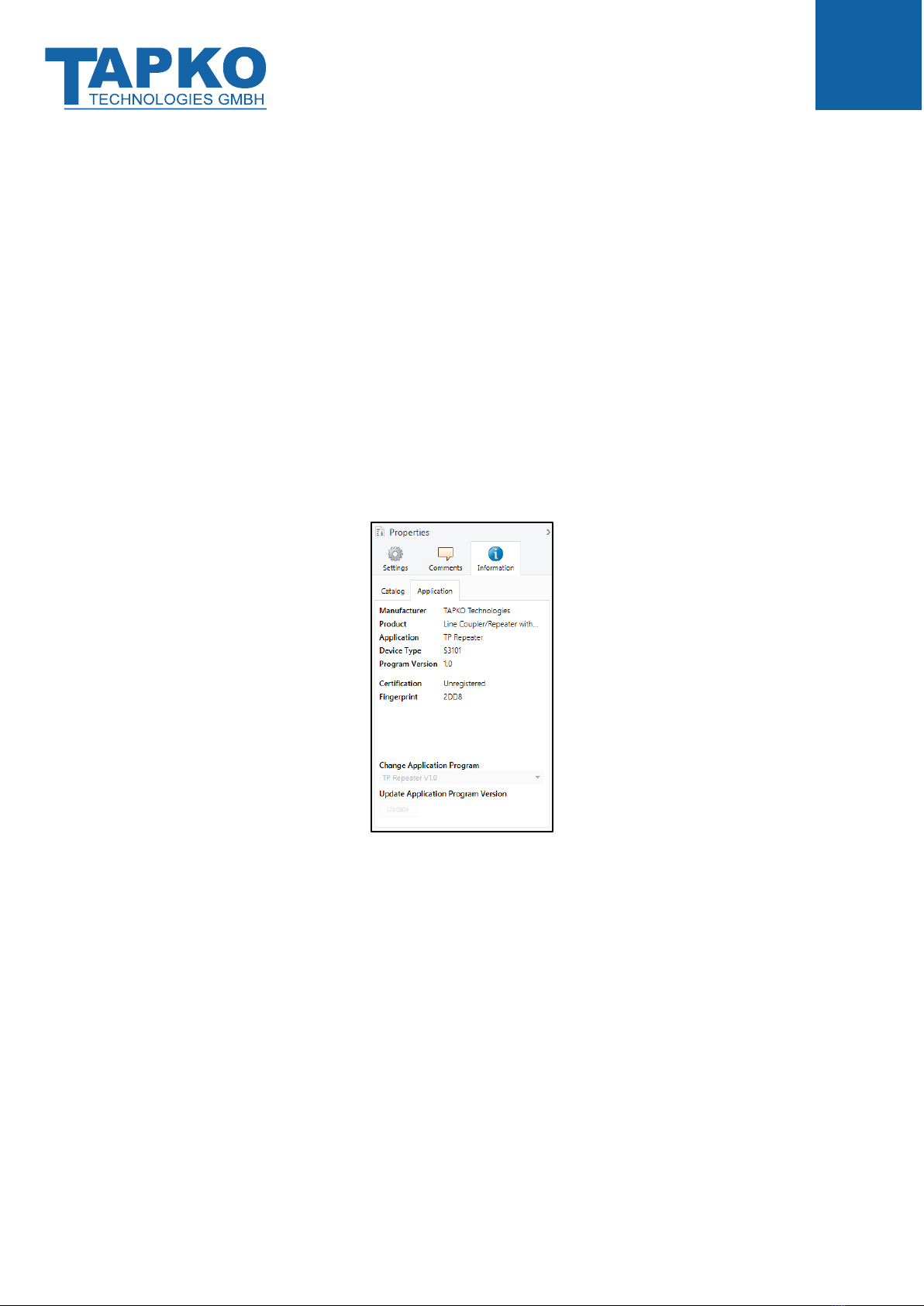
If not configured as Line Coupler, the ETS application program “TP Coupler” has to be
downloaded to the device. Under the ETS Information tab, the application can be changed.
Updating the application program version can also be done here.
Figure 3: TP Coupler Application Program
Operational Description
MECps
- 12 -
2.2 TP Repeater Application
Irrespective of in which line it is processed, any received telegram is routed. Line repeaters
make no use of a filter table.
If a telegram is routed by MECps640 without receiving the corresponding acknowledgement,
i.e. due to a missing receiver or to a transmission error, the telegram will be repeated up to
three times (depending on the ETS setting). With the parameters „Repetitions if errors...“, this
function can be configured separately for each line and both kinds of telegrams. It is
recommended to use the default parameter setting.
If not configured as Line Repeater, the ETS application program “TP Repeater” has to be
downloaded to the device. Under the ETS Information tab, the application can be changed.
Updating the application program version can also be done here.
Figure 4: TP Repeater Application Program

Operational Description
MECps
- 13 -
2.3 KNX Network Installation
2.3.1 Individual Address
For line coupler functionality in a KNX network MECps640 has to use the correct Individual
Address of a line coupler (x.y.0, 1≤ x & y ≤15). In ETS up to 225 addresses can be defined
(from 1.1.0 to 15.15.0).
For area coupler functionality in a KNX network MECps640 has to use the correct Individual
Address of an area coupler (x.0.0, 1≤ x ≤15). In ETS up to 15 areas can be defined.
If MECps640 is used in a KNX system for both purposes, it is necessary to ensure that the
MECps640 used as a line coupler has a line coupler address assigned from a free addressing
area. Following figure illustrates the correct line coupler topology.
Figure 5: Line Coupler Network
Example: If an area coupler with address 1.0.0 already exists on the backbone no line coupler
with address 1.x.0, 1≤ x ≤15 can be added here. Even if no line coupler with address 1.1.0
exists on the subline of the 1.0.0 area coupler. Vice versa, if a line coupler with address 1.1.0
already exists in the installation no area coupler with address 1.0.0 can be added.
Operational Description
MECps
- 14 -
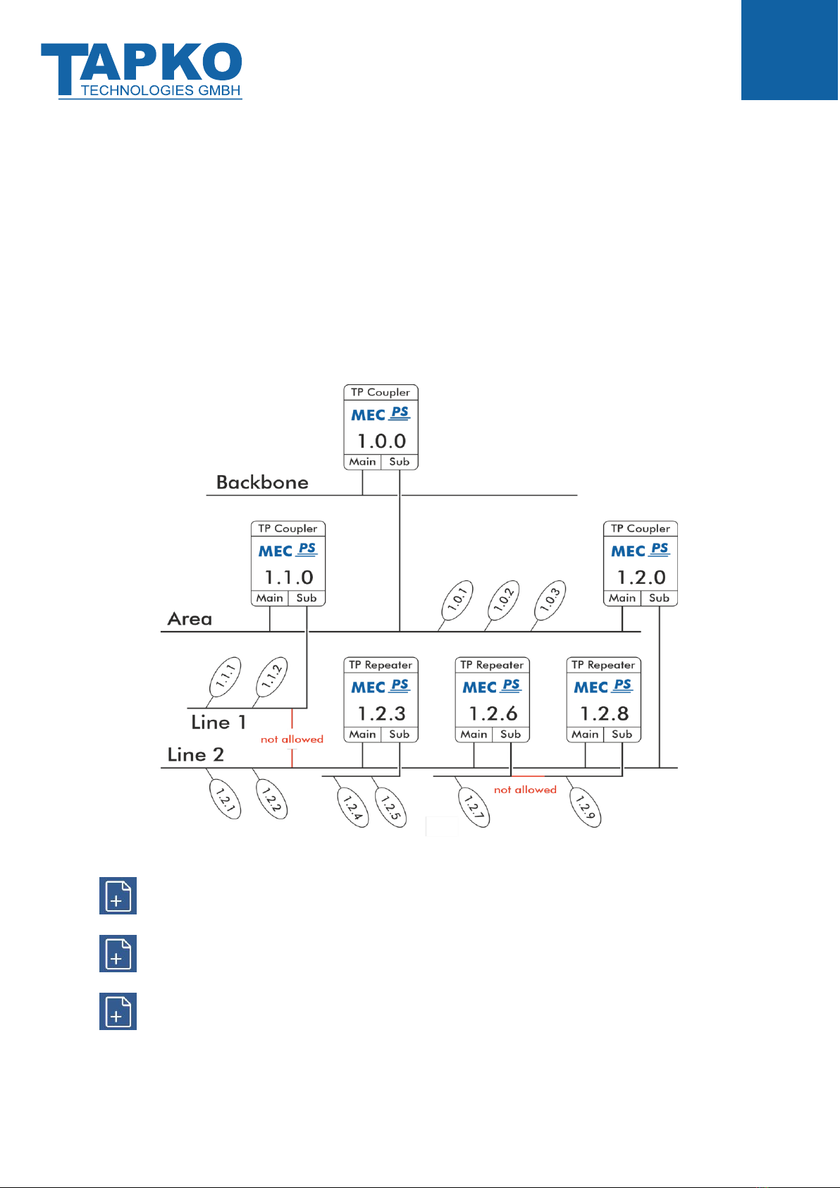
2.3.2 KNX Topology
Up to 15 lines can be connected to an area line, shortly called Area. Up to 64 bus devices find
place on the same line. With usage of line repeaters, such line can be extended to 255 bus
devices having four line segments forming the single KNX TP line. But it is common practice
to insert a new line instead of extending the original one when exceeding 64 bus devices.
The free tree structure of the KNX topology prevents problems caused by circling telegrams
and heavy bus load. To maintain this condition, interconnections between lines or line
segments are strictly forbidden.
Figure 6: Linecoupler Network Topology
Each line and each segment must be powered seperately.
Using repeaters on backbone and main lines is not allowed.
Interconnections are not allowed.

Operational Description
MECps
- 15 -
2.4 Programming
2.4.1 Programming Button
To download Individual Address and/or ETS application, the Programming Mode must be
activated. Successive pressing the Programming Button switches Programming Mode on and
off. LED 7 lighting red indicates Programming Mode is active.
2.4.2 Individual Address Assignment
To make a download and configure the device, an interface connection (IP, USB) to the KNX
bus system is required. When Programming Mode is activated, the ETS is able to start the
download.
To program devices of a line different to which the device used as ETS Current Interface
is connected, a correct topology is mandatory.
The Individual Address can be assigned to the device by setting the desired address in the
properties window of the ETS. When the ETS download is complete, the device restarts itself.
Figure 7: ETS Properties Windows
The device is supplied with the Individual Address 15.15.0 (Factory Default Setting).
The KNX product database entry (available for ETS5 and higher) can be downloaded
from the company website and from the KNX Online Catalog.

Operational Description
MECps
- 16 -
2.5 Special Functions
The Function Button activates MECps640´s special functions. Manual Function and Factory
Reset can be activated. Device settings of MECps640 can be reset to manufacturer default
values with the Factory Reset function. The status of an active special function is indicated by
the LED display (see chapter 1.3 LED Indication of Special Functions).
Table 6: Activation of Special Functions
Step
Manual Function
KNX Bus Reset
Factory Reset
1
Hold Function button for
3 seconds
Short press of Function
button for three times
Hold Function button for
15 seconds
2
LED 1 now is orange
LEDs 2 now is red
LEDs 1/2 now are orange
3
Subline restarts
Hold Function button for
3 seconds
4
Device restarts
2.5.1 Manual Function
During normal operation a rather short press (≈ 3 sec) activates and deactivates the Manual
Function. LED 5 and LED 6 show the current filtering states.
When the Manual Function is active, either all Physical Telegrams or all Group Telegrams or
both pass the MECps640 without filtering. After the Switch-off time period has elapsed,
MECps640 automatically switches back to normal operation. To configure the Manual
Function and set the Switch-off time use the General parameter tab like shown in chapters
3.1 and 4.1. After switching back from Manual Function to normal operation the latest
downloaded parameter setting / filter table entries are active again.
2.5.2 KNX Bus Reset
To reset the secondary KNX bus line (Subline), pressing 3x the Function Button (shortly and in
a row) activates the KNX Bus Reset function.
During the bus reset, the device disconnects the entire bus line from the supplying output
and induces a short circuit for some seconds. LED 1 (State 1) and LED 2 (State 2) light up red
and go off after the reset process is accomplished. Other LEDs are off. The devices connected
to the subline restart during the reset process.

Operational Description
MECps
- 17 -
2.5.3 Factory Reset
A long press (≈ 15 sec) of the Function Button soon followed by a short press (≈ 3 sec)
executes the Factory Reset. After the first press, the LED display lights like described in Table
5: LED Status Display for Factory Reset after first Button Press. After the second press, all
parameters (incl. Individual Address) will be set to factory default. Subsequently, LEDs show
the normal operation display again.

ETS Database Parameters Coupler
MECps
- 18 -
3ETS Database Parameters Coupler
All screen shots are related to the MECps640 database R1-0 in ETS5.
3.1 General
Figure 8: General Tab Parameters
Table 7: General Tab Parameter Settings
ETS Parameter
Settings
[Factory Default]
Comment
Manual Function
disabled
pass all telegrams
pass all Physical telegrams
pass all Group telegrams
[pass all telegrams]
Configuration setting for telegram routing
during Manual Function is active.
Switch-off time
for Manual Function
10 min, 1 hour, 4 hours,
8 hours
[1 hour]
After expiry of this time period the Manual
Function is switched off automatically.

ETS Database Parameters Coupler
MECps
- 19 -
3.2 Main Line
Setting “transmit all” is intended only for testing use. Please do not use for normal operation.
If the parameter “Send confirmation on own telegrams” is set to “yes”, MECip-Sec
systematically sends an ACK on any own routed telegram. For example, since repeaters
do not use filter tables, it is useful to have an ACK sent along with routed telegrams.
Figure 9: Main Line Tab Parameters
Table 8: Main Line Tab Parameter Settings
ETS Parameter
Settings
[Factory Default]
Comment
Telegram routing
Group: filter, Physical: block
Group and Physical: filter
Group: route, Physical: filter
Group and Physical: route
configure
[Group and Physical: filter]
block:
no telegrams are routed.
filter:
telegrams entered in the
filter table are routed.
route:
all telegrams are routed.
configure:
the following parameters
must be set manually.
Group telegrams:
Main group 0…13
transmit all
(not recommended)
block
filter
[filter]
Group telegrams (main group 0…13)
are all routed.
Group telegrams (main group 0…13)
are all blocked.
Group telegrams (main group 0…13)
are routed if entered in the filter table.
Group telegrams:
Main group 14…31
transmit all
(not recommended)
block
filter
[filter]
Group telegrams (main group 14…31)
are all routed.
Group telegrams (main group 14…31)
are all blocked.
Group telegrams (main group 14…31)
are routed if entered in the filter table.

ETS Database Parameters Coupler
MECps
- 20 -
ETS Parameter
Settings
[Factory Default]
Comment
Physical telegrams
transmit all
(not recommended)
block
filter
[filter]
•Physical telegrams are all routed.
•Physical telegrams are all blocked.
•Depending on the Individual Address
Physical telegrams are routed.
Physical telegrams:
Repetition
if errors
on main line
no
up to 3 repetitions
only one repetition
[up to 3 repetitions]
After main line transmission error (e.g. due
to missing receiver) Physical telegrams
•are not repeated.
•are repeated max. 3 times.
•are repeated once.
Group telegrams:
Repetition
if errors
on main line
no
up to 3 repetitions
only one repetition
[up to 3 repetitions]
After main line transmission error (e.g. due
to missing receiver) Group telegrams
•are not repeated.
•are repeated max. 3 times.
•are repeated once.
Telegram
confirmation
on main line
if routed
always
[if routed]
•Routed telegrams to the subline are
confirmed by an ACK on the main line.
•Each telegram on the mainline is
confirmed by an ACK.
Send confirmation on
own telegrams
yes
no
[no]
•Telegrams sent out to the mainline are
confirmed by added ACK.
•No ACK confirmation.
Table of contents
Other TAPKO Cables And Connectors manuals


