TAPKO MECps 640 User manual
Operating Instructions
MECps
640
Release version/date: R1.3 / September 2020
© 2001-2020 TAPKO Technologies GmbH
Im Gewerbepark A15, 93059 Regensburg, Germany
Details, modifications and corrections may be subject to change without notice. TAPKO gives no warranty for the accuracy of the document. All rights reserved.
Product description
Connectors, buttons and LEDs description
The combined device MECps640 merges the functionalities of two
different system devices. In addition to coupling two TP lines and
providing full TP line coupler functionality the MECps640 powers the
secondary KNX TP Line. Having a very small footprint of only two units, the
efficient device generates a stable KNX system voltage of 30V DC. The
flexible MECps640 can be used as line coupler, area coupler or repeater.
Basic line coupler functionality is coupling a TP main line with a TP subline
providing galvanic isolation in between. Traffic can be filtered according to
the installation place in the bus system hierarchy or according to the built-
in filter tables for group-oriented communication. Long messages with up
to 240 bytes APDU are supported. Configuring from the subline can be
disabled. The subline can be reset via push-button press.
To ease commissioning and troubleshooting, functions like a configurable
Manual Function to temporarily deactivate filtering are available. The
Manual Function can be activated by a single button press on the device
and its switch-off after a pre-set time period is automatic.
MECps640 is suitable for 35 mm DIN rails and installation in distribution
boards. The supply of subline is overload-proof and short circuit
protected. LEDs indicate the device state and the state of the lines.
Configuring can be done with the ETS.
Requirements of Directives EMC, RoHS and LVD are met. Standards for
residential, commercial, and industrial environments are fulfilled. The full
text of the EU declaration of conformity is available at the following
internet address: www.tapko.de/ce
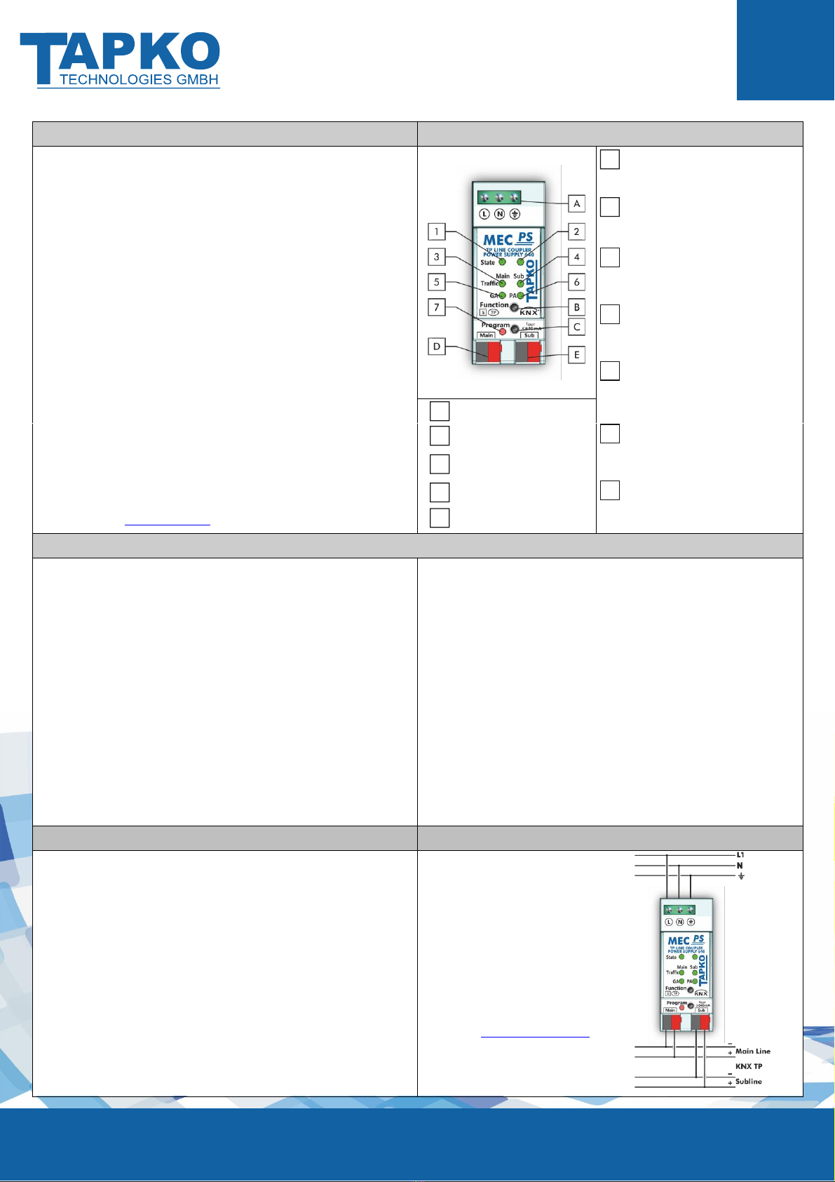
State 1
green: Main line OK
orange: Manual Function active
red: KNX bus reset of subline
State 2
green: Subline OK/Out. current<640mA
orange: Output current is 640…900 mA
red: Overload or KNX bus reset
Telegram traffic KNX TP (Main line)
green (blinking):
Telegram traffic extent
red (blinking):
Transmission error
Telegram traffic KNX TP (Subline)
green (blinking):
Telegram traffic extent
red (blinking):
Transmission error
Group Address routing
green: Filter active
orange: Route all
red: Block all
<off>: Main line / subline different
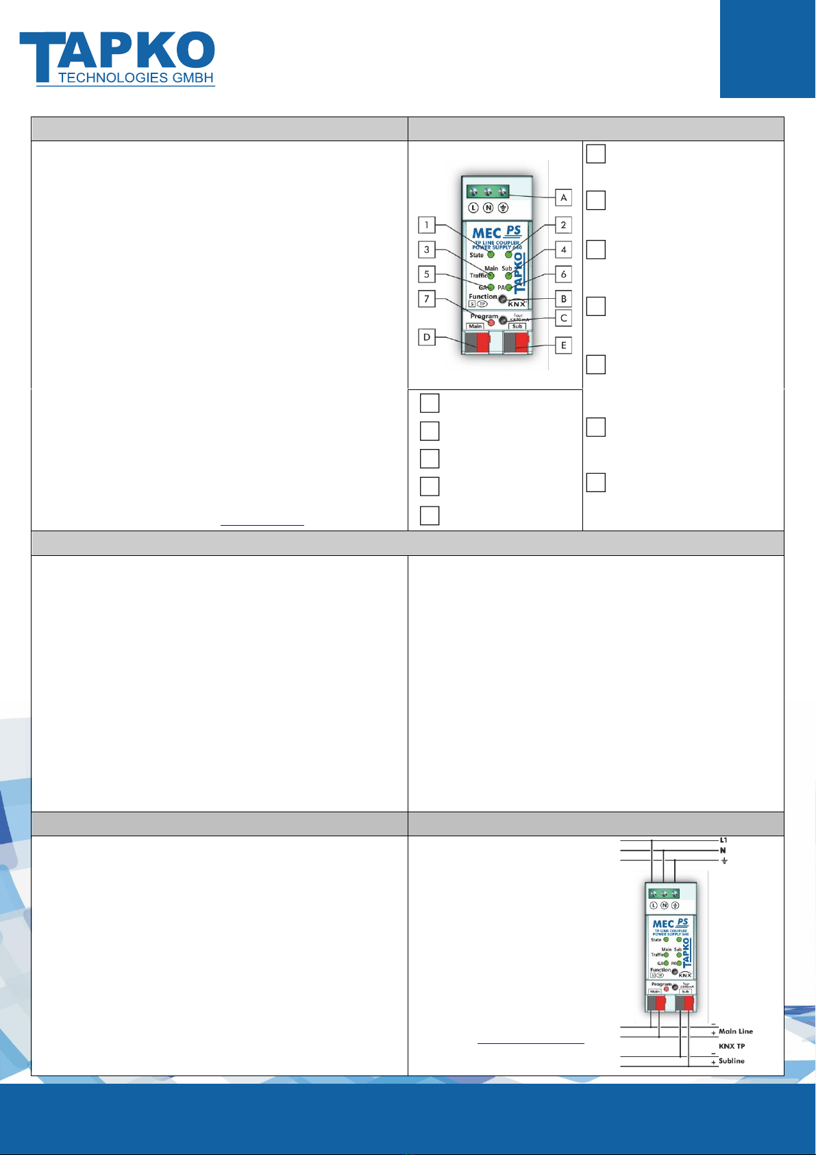
Supply voltage terminals
Function button
Physical Address routing
green: Filter active
orange: Route all
red: Block all
<off>: Main line / subline different
Programming button
KNX TP connector (Main line)
Programming LED
red: Programming Mode active
KNX TP connector (Subline)
Technical specifications
Power input
Mains voltage:
Leakage loss (open-circuited):
Leakage loss (normal):
Power consumption (normal):
Power consumpt. (max., overload):
Housing
Dimensions (HxWxD):
Mounting (IEC60715):
Width in space units:
Mains voltage connection:
KNX bus connections:
Weight:
Environmental conditions
Operating temperature:
Storage temperature:
Ambient humidity:
230 V AC ±15 % @ 50 Hz
0.9 W
4.4 W
23.2 W
39.2 W
94 x 36 x 71 mm
35 mm top-hat rail (TH35)
2 modules at 18 mm
Screw terminals 0.3…2.5 mm2
(torque 0.4 Nm)
KNX TP connector (red/black)
188 g
-5…45 °C
-20...60 °C
5…93 % (non-condensing)
Power output
KNX output voltage:
Rated current:
Maximum current (total output):
Mains failure bridging time:
Efficiency at nominal load:
Electrical safety
Pollution degree (IEC60664):
Protection type (IEC60529):
Overvoltage category (IEC60664):
Approbation (ISO/IEC14543-3):
CE Marking
EU Directives:
Standards:
28…31 V DC (SELV)
640 mA
1.2 A
> 100 ms
81 %
2
IP20
III
KNX-certified
LVD (2014/35/EU)
EMC (2014/30/EU)
RoHS (2011/65/EU)
EN50581, EN61000-6-2/-3,
EN IEC 63044-5-1/-2/-3,
EN61558-1/-2-16
Mounting, commissioning and safety notes
Installation and maintenance
•After connecting, the device works with its default settings as intended
•The device may only be installed and put into operation by a qualified electrician
or authorized person
•For planning and construction of electric installations the appropriate
specifications, guidelines and regulations in force of the respective country have to
be complied
•For mounting use an appropriate equipment according to IEC60715
•Installation only in distribution boards and enclosed housings
•Installation only on a 35 mm DIN rail (TH35)
•Terminals and metal parts under current must be completely covered against
touching
•Contact protection must be provided through the control cabinet
•It must be not possible to remove the cover without aid of a tool
•Connect the KNX bus line as for common KNX bus connections with a KNX bus
cable, to be stripped and plugged into the KNX TP connector
•Do not damage electrical insulations when connecting
•Installation only in dry locations
•For configuring, use the ETS
•Accessibility of the device for
operation and visual inspection must
be provided
•The housing must not be opened
•Protect the device from moisture,
dirt and damage
•The device needs no maintenance
•If necessary, the device can be
cleaned with a dry cloth
•In the case of damage (at storage,
transport) no repairs may be carried
out by unauthorized persons
•Configuration details and ETS
database: www.tapko.de/mecps640
1
2
3
4
5
A
B
6
C
D
7
E
Betriebs-/Montageanweisung
MECps
640
Version/Veröffentlichung: R1.3 / September 2020
© 2001-2020 TAPKO Technologies GmbH
Im Gewerbepark A15, 93059 Regensburg, Germany
Hier enthaltene Daten können sich ohne vorherige Ankündigung ändern. TAPKO garantiert nicht die Richtigkeit und Vollständigkeit des Dokuments. Alle Rechte vorbehalten.
Produktbeschreibung
Anschlüsse, Tasten und LEDs
Das Kombi-Gerät MECps640 vereint die Funktion zweier Systemgeräte auf
sich. Zum Verbinden von zwei KNX TP Linien stellt der MECps640 die TP
Linienkoppler-Funktion bereit und versorgt zudem die sekundäre KNX TP
Linie. Mit einem sehr geringen Platzbedarf von nur 2 TE erzeugt das
effiziente Gerät eine KNX Systemspannung von 30V DC. Der flexible
MECps640 kann als Linienkoppler, Bereichskoppler und als Repeater
eingesetzt werden.
Grundfunktion des Linienkopplers ist die Kopplung von Hauptlinie und
Nebenlinie. Beide Linien sind galvanisch getrennt. Der Telegrammverkehr
kann topologisch und gruppenorientiert gefiltert werden. Lange
Telegramme mit bis zu 240 Bytes APDU werden unterstützt. Die
Konfigurierung über die Nebenlinie ist abschaltbar. Die Nebenlinie kann
per Tastendruck zurückgesetzt werden.
Zur Erleichterung von Inbetriebnahme und Fehlersuche stehen Funktionen
wie die Manuell-Funktion zur kurzzeitigen Deaktivierung der Filterung auf
Tastendruck zur Verfügung. Der MECps640 schaltet dann nach einer
voreingestellten Zeitspanne automatisch wieder auf Normalbetrieb zurück.
Der MECps640 ist ein REG für 35 mm DIN-Schienen und für den Einbau in
einen Verteilerkasten vorgesehen. Die Versorgung der Nebenlinie ist
überlastsicher und kurzschlussfest. LEDs zeigen den Zustand des Geräts
und der Linien an. Die Konfigurierung ist mit der ETS vorzunehmen.
Die Anforderungen der Direktiven EMC, RoHS und LVD sowie Standards
für Wohn & Gewerbebereiche als auch Industriebereiche werden erfüllt.
Der vollständige Text der EU-Konformitätserklärung ist unter der
folgenden Internetadresse verfügbar: www.tapko.de/ce
Status 1
grün: Hauptlinie OK
orange: Manual-Funktion an
rot: KNX Bus Reset der Nebenlinie
Status 2
grün: Nebenlinie OK/Ausg.str.<640mA
orange: Ausgangsstrom ist 640…900 mA
rot: Überlast oder KNX-Bus Reset
Telegrammverkehr KNX TP (Hauptl.)
grün (blinkend):
Telegrammverkehr
rot (blinkend):
Übertragungsfehler
Telegrammverkehr KNX TP (Nebenl.)
grün (blinkend):
Telegrammverkehr
rot (blinkend):
Übertragungsfehler
Gruppenadressen Filter
grün: Filter aktiv
orange: Alle weiterleiten
rot: Alle blockieren
<off>: Haupt-/Nebenl. unterschiedlich
Netzanschluss
Funktionstaste
Physikalische Adressen Filter
grün: Filter aktiv
orange: Alle weiterleiten
rot: Alle blockieren
<off>: Haupt-/Nebenl. unterschiedlich
Programmiertaste
KNX TP Anschluss (Hauptlinie)
Programmier-LED
rot: Programmiermodus an
KNX TP Anschluss (Nebenlinie)
Technische Angaben
Versorgung
Netzspannung:
Verlustleistung (Leerlauf):
Verlustleistung (normal):
Leistungsbedarf (normal):
Leistungsbedarf (max., Überlast):
Gehäuse
Maße (HxBxT):
Montage (IEC60715):
Breite:
Netzanschluss:
KNX Bus-Anschlüsse:
Gewicht:
Umgebungsbedingungen
Arbeitstemperatur:
Lagertemperatur:
Umgebende Feuchte:
230 V AC ±15 % @ 50 Hz
0,9 W
4,4 W
23,2 W
39,2 W
94 x 36 x 71 mm
35 mm-Schiene (DIN, TH35)
2 TE zu je 18 mm
Schraubklemmen 0,3…2,5 mm2
(Anzugsdrehmoment 0,4 Nm)
KNX-Klemme (rot/schwarz)
188 g
-5…45 °C
-20...60 °C
5…93 % (nicht-kondensierend)
Ausgangsleistung
KNX Busspannung:
Nennstrom:
Maximalstrom (gesamt):
Überbrückungszeit bei Netzausfall:
Effizienz bei Normallast:
Elektrische Sicherheit
Verschmutzungsgrad (IEC60664):
Schutzart (IEC60529):
Überspannungskategorie (IEC60664):
Freigabe (ISO/IEC14543-3):
CE Kennzeichnung
EU-Direktiven:
Standards:
28…31 V DC (SELV)
640 mA
1,2 A
> 100 ms
81 %
2
IP20
III
KNX-zertifiziert
LVD (2014/35/EU)
EMC (2014/30/EU)
RoHS (2011/65/EU)
EN50581, EN61000-6-2/-3,
EN IEC 63044-5-1/-2/-3,
EN61558-1/-2-16
Montage, Inbetriebnahme und Sicherheit
Installation und Wartung
•Nach dem Anschließen arbeitet das Gerät mit seinen Standardeinstellungen wie
vorgesehen
•Das Gerät darf nur von einer Elektrofachkraft oder autorisiertem Fachpersonal
installiert und in Betrieb genommen werden
•Bei der Planung und Errichtung von elektrischen Anlagen sind die einschlägigen
Richtlinien, Vorschriften und Bestimmungen des jeweiligen Landes zu beachten
•Zur Montage ein geeignetes Werkzeug nach IEC60715 verwenden
•Installation nur in Verteilerkästen oder geschlossenen Gehäusen
•Installation nur auf geeigneter DIN-Hutschiene (TH35)
•Stromführende Teile müssen vollständig abgedeckt werden
•Der Berührschutz muss durch den Schaltschrank gewährleistet sein
•Es darf nicht möglich sein, die Abdeckung ohne Hilfe eines Werkzeuges zu
entfernen
•Die KNX-Buslinie, wie für alle üblichen KNX-Anschlüsse, mit abisoliertem KNX-
Buskabel und KNX TP-Klemme anschließen
•Beim Anschließen nicht die elektrischen Isolationen beschädigen
•Installation nur in trockener Umgebung
•Zum Konfigurieren die ETS verwenden
•Die Zugänglichkeit zum Gerät muss
aus Gründen der Bedienbarkeit und
Inspektion stets gewährleistet sein
•Das Gehäuse darf nicht geöffnet
werden
•Gerät vor Feuchtigkeit, Schmutz und
Beschädigung schützen
•Das Gerät ist wartungsfrei
•Wenn nötig, das Gerät mit einem
trockenen Tuch reinigen
•Bei Beschädigung (bei Transport,
Lagerung) darf keine Reparatur
vorgenommen werden; Gerät
zurückschicken
•Konfiguration-Details und ETS-
Datenbank: www.tapko.de/mecps640
1
2
3
4
5
A
B
6
C
D
7
E
Table of contents
Languages:
Other TAPKO Cables And Connectors manuals


Popular Cables And Connectors manuals by other brands


Burndy
Burndy Continental Industries thermOweld CR-1 instructions

Nauticam
Nauticam M24A3R140 user manual

Telran communications
Telran communications 500255 user manual

Zamel
Zamel GPRU manual

3M
3M 103 12R1-00 Series instructions

PCE Health and Fitness
PCE Health and Fitness TOPTAURUS2 057 Series Assembly instructions