manuals.online logo
Brands
  1. Home
  2. •
  3. Brands
  4. •
  5. Tapmatic
  6. •
  7. Power Tools Accessories
  8. •
  9. Tapmatic 30TC/DC Guide

Tapmatic 30TC/DC Guide

Safety and Operaon for TC/DC Self Reversing Tapping Aachments
ISO 9001 CERTIFIED: 802 CLEARWATER LOOP, POST FALLS, ID 83854
PHONE: (800) 854-6019 OR (208) 773-2951, FAX: (208) 773-3021, E-MAIL: info@tapmac.com, WEB: www.tapmac.com
1
Warning: To avoid serious injury and ensure best results for your tapping operaon, please read carefully all
operator and safety instrucons provided for this tapping unit as well as all other safety instrucons that are ap-
plicable, especially those for your machine.
1. Proper Clothing: The rotang spindle of a machine tool can snag loose ng clothing, jewelry or long hair.
Never wear jewelry, long sleeves, neckes, gloves or anything else that could become caught when operang a
machine tool. Long hair must be restrained or need to prevent it from becoming entangled in rotang spindle.
2. Proper Eye Protecon: Always wear safety glasses with side shields to protect your eyes from
ying parcles.
3. Proper Work Piece Fixturing: Never hold the work piece or the vise it is held in by hand. The
workpiece must be clamped rmly to the table of the machine so that it cannot move, rotate or
li.
4. Proper Stop Arm/Torque Bar Installaon for Self-Reversing Aachments On Convenonal
Machines.
Always mount a torque bar to hold the tapping aachments stop arm from rotang.
The torque bar must be mounted securely to the table or quill of your machine. The
torque bar installaon must be stronger than the largest tap in the capacity range of
your tapping aachment. The surface of the torque bar must be smooth to allow the
stop arm to slide freely when feeding in and out of the hole. Order Tapmac Torque Bars
shown.
Never extend the length of the standard stop arm supplied with your tapping aach-
ment. A lengthened stop arm could break free hing the operator and causing serious
injury.
Never hold the stop arm by hand. On reversal, full power of the machine is transmied through the
stop arm and the operator could be seriously injured.
5. Do not exceed the maximum speed for the tapping head: Speed is a crical factor in tapping.
Please always refer to recommended tapping speed chart. Tapmac torque control reversing tap-
ping aachments employ a planetary gear for increased speed in reverse. The revoluons per minute when revers-
ing out of the hole will be 1.75 mes faster than the machine spindle speed. It is strongly recommended that you
consider the Average Tapping Speed rather than machine speed when calculang cycle me. For example if ma-
chine speed is 1500 RPM, reverse speed is 2625 RPM making your Average Tapping Speed 2062 RPM. You must not
exceed the maximum allowable speed marked on your tapping aachment.
6. Always be aware of the potenal hazards of a machining operaon: Somemes working with your machine can
seem roune. You may nd that you are no longer concentrang on the operaon. A feeling of false security can
lead to serious injury. Always be alert to the dangers of the machines with which you work. Always keep hands,
parts of the body, clothing, jewelry and hair out of the areas of operaon when the machine spindle is rotang. Are-
as of operaon include the immediate point of machining and all transmission components including the tapping
aachment. Never bring your hand, other parts of the body or anything aached to your person into any of these
areas unl the machine spindle is completely stopped.
Quill Clamp
Capacity Ø
Order No. Max Tap Size
1 1/2”-3/8”
38-60 mm
29099 1/2” or M12
2 3/8”-4 1/2”
60-114 mm
290991 3/4” or M20
Torque Bar
Assembly
Order No. Max Tap Size
Table Mount 29097 3/4” or M20
Heavy Duty
Table Mount
29096 1 3/4” or M42
Safety and Operaon for TC/DC Self Reversing Tapping Aachments
ISO 9001 CERTIFIED: 802 CLEARWATER LOOP, POST FALLS, ID 83854
PHONE: (800) 854-6019 OR (208) 773-2951, FAX: (208) 773-3021, E-MAIL: info@tapmac.com, WEB: www.tapmac.com
2
Warning: To avoid serious injury and ensure best results for your tapping operaon, please read carefully all
operator and safety instrucons provided for this tapping unit as well as all other safety instrucons that are ap-
plicable, especially those for your machine.
7. Be aware of any other applicable safety instrucons/requirements especially those for your machine.
8. The tapping aachment housing, drive spindle and tap itself can become hot to the touch aer operaon. Use
cauon when removing the aachment from the machine or handling.
Check List For Good Tapping
1. Never use this tapping aachment before reading all safety instrucons for it as well as the machine it is to be
used on.
2. Be sure tap is sharp and of correct design for your applicaon.
3. Be sure tap is in proper alignment with the drilled hole.
4. Be sure the machine speed is correct.
5. Be sure you are following the correct feed rate for the tap based on the pitch of the tap and revoluons per
minute.
6. Make sure the drilled hole is the correct size.
7. Be sure the machine stop is set correctly to avoid hing the boom of a blind hole. See Controlled Depth Tap-
ping.
8. Be sure to allow for sucient chip clearance especially when tapping blind holes.
9. Make sure the work piece is clamped rigidly so that it is not able to move, rotate, or li.
10. Make sure there is enough clearance between the tap and work piece at the starng posion and the retract
posion to be sure the tap is clear of the hole upon retracon. Remember the tapping aachment spindle ex-
tends during reversal out of the hole.
11. Make sure to mount a strong torque bar from the table of the machine, or to the non-rotang quill, to prevent
the stop arm from rotang. The torque bar must be stronger than the largest tap in the tapping aachments
capacity. It must also have a smooth surface so that the stop arm slides freely when feeding in and out of the
hole.
12. Make sure to use the proper cung uid/lubricant for the applicaon.
References for this safety informaon include but are not limited to: American Naonal Standards Instute, ANSI B11.8-1983, Coastal Video Communicaons Corporaon Machine Guarding Copy right 1994,
Society of Manufacturing Engineers Tool and Manufacturing Engineers Handbook Volume 1 Machining Library of Congress Catalog No 82-060312
Safety and Operaon for TC/DC Self Reversing Tapping Aachments
ISO 9001 CERTIFIED: 802 CLEARWATER LOOP, POST FALLS, ID 83854
PHONE: (800) 854-6019 OR (208) 773-2951, FAX: (208) 773-3021, E-MAIL: info@tapmac.com, WEB: www.tapmac.com 3
This tapping aachment can be used on all types of manually operated machines with rotang spindles. It can also be used in
many automated applicaons. IMPORTANT Always follow all instrucons from your machine manufacturer.
Installing the Arbor into the tapping aachment: Clean the thread or taper of both the
arbor and the mount of the tapping head. Then install the arbor into the mount securely.
If it is a taper mount, twist the arbor as you push it into the tapping heads mount.
Then use a mallet to give a sharp blow to the end of the arbor, to seat it into the
taper mount of the tapping head.
To remove a taper mount arbor, give the arbor several sharp blows on the side
using a mallet.
Installing a Rubber Flex Collet into the tap chuck nut: If the tap has a male center, it should be ground o:
Tightening the back jaws and the nut:
Place rubber -
ex collet in
spindle
Remove
point...
1. Open
the back
jaws
using the
key.
Note: In order to insure the tap runs concentrically, and avoid damage to back jaws or collet, it is important to follow the above steps.
2. Slide tap all
the way in so
the tap
square goes
into the
back jaws
Installing the stop arm:
Use the retaining ring to
mount the stop arm to the
gear carrier at the boom of
the housing.
In order for the Tapping Head to
reverse, the stop arm must be
prevented from rotang.
See also Proper Stop Arm/Torque
Bar Installaon on page 1.
Then push
and thread
nut over the
collet.
So tap
square will
go into
back jaw
fully
3. Lightly
ghten the
nut by hand.
This holds the
tap concentric.
4. Tighten
the back
jaw with
the key.
5. Tighten
the collet
nut with
the
wrenches
30X and 30TC/DC The smaller models do
not have an adjustable
back jaw. Instead they
have a xed tap jaw
with three slots. Simply
slide the tap into the
jaw fully so that the tap
square ts into the
correct slot in the tap
jaw. Please note that
the two set screws are
only for driving and
retaining the tap jaw.
They are not intended
to ghten against the
tap square.
Safety and Operaon for TC/DC Self Reversing Tapping Aachments
ISO 9001 CERTIFIED: 802 CLEARWATER LOOP, POST FALLS, ID 83854
PHONE: (800) 854-6019 OR (208) 773-2951, FAX: (208) 773-3021, E-MAIL: info@tapmac.com, WEB: www.tapmac.com
Material Low
Carbon
Steel
High-
Carbon
Steel
Tool
Steel
Hard
SS 303,
304,
316
SS 410,
430,
17-4
Hard
SS 17-4
Anneal.
Titan.
Alloys
Ni
Alloys
Alum
Alloys
Alum
Die
cast
Magn. Brass,
Bronze
Copper Cast
Iron
M/min
(/min)
10-20
(33-66)
8-12
(26-39)
4-6
(13-20)
6-12
(20-39)
3-5
(10-16)
6-12
(20-39)
4-8
(13-26)
3-5
(10-16)
15-25
(49-82)
10-15
(33-49)
15-25
(49-82)
15-25
(49-82)
8-12
(26-39)
10-20
(33-66)
Tapping Speeds: The following speed recommendaons are for reference only. Please consult tap manufacturer for your specic tap. Do not
exceed the maximum speed for tapping aachment shown on the housing.
Tap Diameter in mm
RPM = (M/min) x 318.5 RPM = (ft/min) x 3.82
Tap Diameter inch
4
The torque control helps prevent tap breakage, especially
when tapping blind holes. Tightening the cap down to the
higher number sengs on the reference scale increases
torque. To set the torque, use a new tap and begin with a
low number (low torque) seng. Try to tap the hole.
When the clutch slips, there will be no sound from the ber disc clutch. Stop the
machine and ghten the cap further. Repeat this process unl you can drive a
sharp tap to depth. Give the cap a half turn more and lock it using the set screw in
the side of the cap. This system saves the tap from breaking if you accidentally go too deep in a blind hole. It also warns you
when your tap is becoming dull so that you can replace it before it breaks. Make note of the reference number to save me
when the same job comes up again.
Self-Feed: Every tapping aachment has a self-feed. What is self-feed? Self feed is the addional depth that the tap will go
into the hole aer you feed to the stop on your machine. See the next page for the self-feed distances for the TCDC models.
Seng the stop on your machine for tapping: Please note that the tap will connue
to go deeper into the hole by the self-feed distance. The total tapping depth will be
based on the depth you set with your machine stop plus the self-feed of the tapping
aachment. For example if you would like a tapping depth of 10mm and the tapping
aachment’s self-feed is equal to 3 to 4mm, start by seng the machine stop to
allow the tap to enter the hole just 6mm. Aer tapping your rst hole, check the
depth and make any necessary adjustments to the machine stop. Always set the
machine stop to avoid tapping too deep and hing the boom of the hole. The
torque control is intended to only be a safety back up in case you accidentally go
too deep.
Tapping Holes: When tapping, it is not necessary to apply any pressure as you feed
in. The tap will follow it’s own pitch in and out of the hole. Just follow along with the tap, keeping up with it as it enters
the hole. Aer you reach the machine stop, li up on the feed handle to retract the tap. The tapping aachment will
automacally reverse the taps rotaon when you retract. Please note that the speed increases by 1.75 to 1 in reverse,
so you will need to feed out of the hole almost twice as fast as you did feeding in. Be sure to keep up with the tap as it
exits the hole. If you are feeding too slowly going in or out, the tap will stop and start and you will hear a clicking
sound. This clicking sound is not the clutch slipping. If this occurs you need to feed faster to keep up with the tap.
Please note that if the clutch slips because the torque is not set high enough there will not be a sound coming from the
clutch.
Seng the pre-selecve torque control:
Clutch
adjust-
ment cap
Safety and Operaon for TC/DC Self Reversing Tapping Aachments
ISO 9001 CERTIFIED: 802 CLEARWATER LOOP, POST FALLS, ID 83854
PHONE: (800) 854-6019 OR (208) 773-2951, FAX: (208) 773-3021, E-MAIL: info@tapmac.com, WEB: www.tapmac.com 5
TC/DC Models Only: Seng the Hard Start/Depth control collar: Below are gures showing the dierent sengs that can
be used.
Cushion Seng: For normal tapping it can be
helpful to have compression or cushion when
starng the tap into the hole. This is also need-
ed for re-entering a previously tapped hole.
Self Feed for tapping in this posion is...
30TC/DC= 3 to 4mm
50TC/DC= 6 to 7mm
70TC/DC= 9 to 10mm
Hard Start: Use this posion for more
accurate depth control. Turn the collar
unl it just contacts the boom of the
housing/gear carrier. Push up against
the Rubber Flex spindle and it should
not compress. Self Feed for tapping in
this posion is...
30TC/DC approx. 3mm
50TC/DC approx. 6mm
70TC/DC approx. 9mm
Reduced Self Feed:
Self Feed can be reduced by turning the
collar up further, beyond Hard Start. The
Rubber-Flex spindle will be extended, and
this reduces the self feed. Reducing the
Self Feed is helpful when tapping shallow depth holes. Below
are the recommended adjustments for each model.
30TC/DC Adjust 1 revoluon further, beyond Hard Start…
Self Feed approx. 2mm
50TC/DC Adjust 1 revoluon further...Self Feed approx. 4.5mm
Adjust 2 revoluons...Self Feed approx. 3mm
70TC/DC Adjust 1 revoluon further… Self Feed approx. 7.5mm
Adjust 2 revoluons...Self Feed approx. 6mm
Adjust 3 revoluons… Self Feed approx. 4.5mm
Note! Adjusng further than the above recommendaons can
eliminate the tapping aachments forward drive.
Line these
up as
shown.
When adjusng the posion of the
depth control collar, always turn by
increments of one complete revolu-
on, so that locking set screw is
aligned with the at on the spindle.
Line these up
Secure the collar posion with screw.
Lubricaon: This unit is pre-lubricated at the factory and ready for use. Aer 600 hours we recommend parally disassembling,
cleaning and applying new grease. We recommend using a high quality NLGI 2 type of grease. We recommend returning the Tap-
ping Aachment to Tapmac for maintenance and repair, but if you would like to do this at your own facility, please follow the in-
strucons shown on the next page. Please let us know if we can be of help.
Cung Tool Lubricaon: For the best results and longest life for your cung tools, be sure to use the proper cung uid / lubri-
cant based on your applicaon and the type of material the work piece is made from.
ISO 9001 CERTIFIED- 802 Clearwater Loop, Post Falls, ID 83854, Phone: 800 854-6019, 208 773-8048, FAX: 208 773-3021, www.tapmatic.com
30TC/DC Wrench Set
Qty. Order No. Description
150332 332X Stop Arm
150340 340X Stop Arm Ring
127078 5/64" Hex Key
128050 1/2" Wrench
128062 5/8" Wrench
129030 30 Series Spanner Wrench
(Thread Mounts Only)
50TC/DC Wrench Set
Qty. Order No. Description
156532
156540
128075
128097
1
27223
127078
129050
5032XB Stop Arm
5040XB Stop Arm Ring
3/4" Wrench
31/32" Wrench
3mm Hex Key
5/64" Hex Key
50 Series Spanner Wrench
(Thread Mounts Only)
70TC/DC Wrench Set
Qty. Order No. Description
150732 732X Stop Arm
150740 740X Stop Arm Ring
127078
1
27224
128097
5/64" Hex Key
4mm Hex Key
31/32" Wrench
128131 1 5/16" Wrench
129085 #5 Hook
129090 Spring Puller
129070 70 Series Spanner Wrench
(Thread Mounts Only)
6
Parts Listing: 30, 50 & 70TC/DC Self-Reversing Tapping Units
6
ISO 9001 CERTIFIED- 802 Clearwater Loop, Post Falls, ID 83854, Phone: 800 854-6019, 208 773-8048, FAX: 208 773-3021, www.tapmatic.com
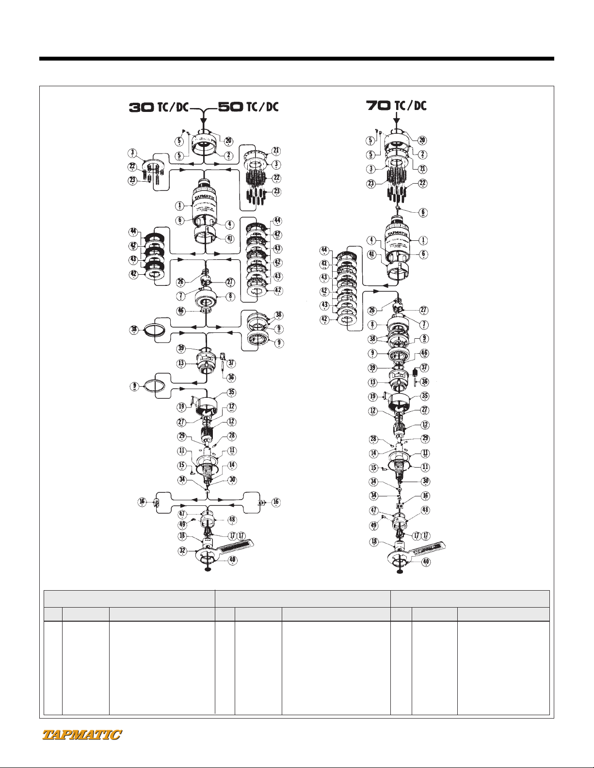
IDENT PART NAME 30TC/DC 50TC/DC 70TC/DC
1Housing - #6JT 54301 B (1) 54501 B (1) -
1Housing - DINB16 54301 G (1) 54501 G (1) -
1Housing - #33JT 54301 E (1) 54501 E (1) -
1Housing - DIN B 12 54301 F (1) - -
1Housing - 5/16-24 54301 H (1) - -
1Housing - 3/8-24
54301 I (1)
54501 I (1) -
1Housing - 1/2-20 54301 J (1) 54501 J (1) 54701 J (I)
1Housing - 5/8-16 54301 K (1) 54501 K (1) 54701 K (1)
1Housing - 3/4-16 54301 L (1) 54501 L (1) 54701 L (1)
1Housing - 7/8-20 - - 54701 M (1)
1Housing - #3JT - - 54701 C (1)
2X Clutch Adjustment Cap 50302 A (2) 56502 A (2) 50702 A (2)
3X Spring Plate 50303 56503 50703
4X Driver Pins 50304 (3 required) 50704 (3 required) 50704 (3 required)
5X Lock Set Screw 50305 A (3) 50305 A (3) 50305 A (3)
5XX Lock Set Screw Plug 503051 503051 503051
6X Guide Spindle 503061 56506 51720
6XX Upper Spring Hanger - -
60334
7X Clutch Sleeve 50307 50507 50707
8X Clutch Bearing 50308 56508 50708
9X Gear Carrier Bearing (Ball) - 50509 50709
9XA Gear Carrier Bearing (Nylon) 503091 - -
9XX Truarc Ring - 505091 507091
11X Retaining Ring 50311 50511 50711
11XX Gear Washer 503111 505111 507111
12XA Reversing Sleeve 503121 (4) 505121 (4) 507121 (4)
12 XA I Reversing Driver Spring 51312 505122 507122
13X Gear Carrier 503131 54513 54713
14X Drive Spindle 54314 A (5) 54514 A (5) 54714 A (5)
15X Back Jaw Retainer Screw
50715 (2 required) 50715 50715
16X Back Jaw or Tap Jaw 503161 56516 50716
17X Rubber Flex Collet (small)
21600
22100 24100
17XX Rubber Flex Collet (large)
21700
22200 24000
18X Tap Chuck Nut 50318 56518 50718
19X Key 50319 50319 50719
20X Stop Ring 50320 56520 50720
21X Adjustment Thrust Bearing -
565211+68439 (12 req) 64521+692205 (8 req)
22X Clutch Spring (large) 50322 (3 required)
50722 (9 required)
50722 (9 required)
23X Clutch Spring (small) 50323 (3 required 50723 (9 required) 50723 (9 required)
26X Cushion Spring 50326 565261 50726
27X Spring Cup Driver 503271 505271 507271
27XA Reversing Driver 503272 505272 507272
28X Drive Pins 50328 (3required) 56528 (3 required) 50728 (3 required)
29X Guide Spindle Bearing 50329 56529 50729
30X Return Spring 51328 51528 51628
31X Drive Spindle Bearing -(4) -(4) -(4)
32X Stop Arm 50332 56532 50732
33X Guide Spindle Washer 50333 - -
34X Guide Spindle Nut 503341 56534 -
34XA Spring Bearing - - 50734
34XX Spring Bearing Hanger - - 50706
35X Ring Gear 50335 50535 50735
36X Gear Pins 50336 (3 required) 50536 (3 required 50736 (3 required
37X Planet Gears 50337 (3 required) 50537 (3 required) 50737 (3 required)
38X Spacer (and Truarc Ring) 50338 54538 and 56511 54738 and 50611
39X Thrust Washer 50339 50539 50739
40X Truarc Ring 50340 56540 50740
41X Clutch Driver 50341 56541 50741
42X Primary Internal Clutch Plate 50342 56542 50742
42XX Internal Clutch Plate 503421 565421 (2 required 507421 (2 required)
43X External Clutch Plate 50343 56543 (2 required) 50743 (2 required)
44X Clutch Discs 50344 (3 required) 56544 (5 required) 50744 (5 required)
46XA Reversing Sleeve Bushing 503461 505461 507461
47X Friction Washer 50347 50547 50747
48X Depth Control Collar 50348 50548 50748
49X Lock Set Screw 50305 50305 50305
(1) Housing only available as an assembly with Ident. #4X and #6X.
(2) Clutch Adjustment Cap only available as an assembly with Ident #5X and #5XX.
(3) Lock Set Screw comes with Ident. #5XX.
(4) Reversing Sleeve and Drive Spindle Bearing available only as an assembly.
(5) Drive Spindle only available as an assembly with Ident. #29X.
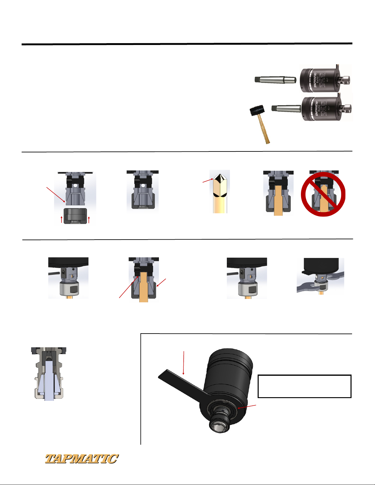
INSTRUCTIONS FOR DISASSEMBLY
1. Remove stop ring (#20X) and unscrew clutch adjustment cap (#2X).
2. Hold unit in vertical position and remove adjustment thrust bearing (#21X). (Models
50 &70TC/DC.)
3. Lift off spring plate (#3X).
4. Carefully invert unit over a clean receptacle. Clutch springs (#22X & 23X) will drop out.
5. Remove tap chuck nut (#18X) and collet (#17X).
6. Remove back jaw retainer screw (#15X).
7. Remove back jaw (#16X).
8a. Remove return spring (#30X) by threading spring puller (supplied with unit) into
tapped hole in part (#34XX), and pulling out to expose spring for removal with spring hook
(also supplied with unit). (Model 70TC/DC.)
8b. Unscrew guide spindle nut (#34X) and remove return spring (#30X).
(Models 30 &50TC/DC.)
9. Remove truarc ring (#40X) and stop arm (#32X).
10. Remove truarc ring (#11X) and gear washer (#11XX).
11. Lift out drive spindle (#14X) and reversing sleeve (#12XA) subassembly from unit.
12. Lift out spacers (#46XA) and (#38X).
13. Lift out clutch sleeve (#7X), clutch driver (#41X), clutch plates (#42X, 42XX, 43X)
and clutch discs (#44X).
14. Lift out cushion spring (#26X) and spring cup driver (#27X).
15. Remove driver pins (#28X) from drive spindle (#14X).
16. Press drive spindle (#14X) out of reversing sleeve (#12XA) subassembly.
17. Do not disassemble planetary gear reversing subassembly (#13X).
REPLACEMENT OF FRICTION WASHER #47X
1. Remove tap chuck nut (#18X.)
2. Unscrew depth control collar all the way off.
3.) Using small screwdriver, flip out used washer (#47X) and insert new one.
INSTRUCTIONS FOR ASSEMBLY
1. Clean and lubricate all parts requiring lubrication thoroughly. Do not get clutch parts wet or oily.
2. Place internal clutch plate (#42X) on clutch sleeve (#7X), then clutch disc (#44X),
then external clutch plate (#43X), then another clutch disc (#44X), then internal clutch plate
(#42XX), and so forth, until you have all plates and discs on clutch sleeve, then line up external
dogs so that you can slip clutch driver (#41X) over complete subassembly.
3. Place cushion spring (#26X) and spring cup driver (#27X) in clutch sleeve (#7X).
4. Insert clutch sleeve (#7X) and clutch driver (#41X) subassembly into housing (#1X), making
sure that 3 holes in clutch driver mate with 3 pins in housing (#1X).
5. Insert spacers (#46XA) and (#38X) into housing (#1X).
6. Press drive spindle (#14X) into reversing sleeve (#12XA) subassembly and insert drive pins
(#28X).
7. Insert complete subassembly into housing (#1X) utilizing key (#19X).
8. Insert gear washer (#11XX) and snap in truarc ring (#11X).
9. Hook return spring (#30X) to spring hanger (#6X) and insert this subassembly into neck end of
housing (#1X) making certain spring hanger is seated properly. (Model 70TC/DC.)
10. Use spring hook (supplied with unit) to expose return spring (#30X) and attach spring
bearing hanger (#34XX) with bearing (#34XA) mounted. (Model 70TC/DC.)
11a. Thread spring puller (supplied with unit) into tapped hole in spring hanger (#34XX) and
carefully lower assembly into drive spindle (#14X) until bearing (#34XA) seats itself, then
unscrew spring puller. (Model 70TC/DC.)
11b Insert return spring (#30X) into drive spindle (#14X) and screw guide spindle nut on
to guide spindle (#6X). (Models 30 & 50TC/DC).
12. Place back jaws (#16X) in drive spindle (#14X) and install back jaw retainer screw (#15X).
13. Insert collet (#17X) into tap chuck nut (#18X) and screw tap chuck nut (#18X) on to
drive spindle (#14X).
14. Insert clutch springs (#22X & 23X) into unit.
15. Place spring plate (#3X) on springs.
16. Place adjustment thrust bearing (#21X) on spring plate (#3X). Models 50 & 70TC/DC.)
17. Screw on clutch adjustment cap (#2X).
18. Install stop ring (#20X).
19. Install stop arm (#32X) and snap on truarc ring (#40X).
7
Parts Listing: 30, 50 & 70TC/DC Self-Reversing Tapping Units
TC/DC Self Reversing Tapping Aachments
ISO 9001 CERTIFIED: 802 CLEARWATER LOOP, POST FALLS, ID 83854
PHONE: (800) 854-6019 OR (208) 773-2951, FAX: (208) 773-3021, E-MAIL: info@tapmac.com, WEB: www.tapmac.com
Repair Service is available at…. Attention: Repair Department
Tapmatic Corporation
802 Clearwater Loop
Post Falls, ID 83854
To Expedite Repair: Return tool direct to Tapmatic Corporation. Tapmatic will inspect the
tool and advise you of the repair costs by fax or email before the repair is completed.
Important: Be sure to return tool complete with collet nut, and if applicable stop arm and
back jaw, because otherwise these missing parts would be added to every non-warranty re-
pair.
Cost Notification: Tapmatic will FAX or E-mail a cost notification to you, soliciting your ap-
proval before repairs are completed. If it is determined that a tool cannot be repaired, at the
customer’s request, Tapmatic will return the disassembled parts. We are not able to reas-
semble a tool using damaged or worn out parts.
Optional Return Procedure: Tools may also be returned for repair through your local Tap-
matic Distributor. They will ship the tool to us and include instructions for the repair and re-
turn. You may already have an open account with them which facilitates the handling of in-
voicing.
Priority Service: Tapmatic services tools returned for repair in the order in which they are
received. All tools will be evaluated and repaired within three weeks from the date they arrive
subject to receiving the customer’s approval to proceed with the repair.
Priority is given to tools shipped to us by overnight or second day.
If a repair is sent to us by UPS ground or similar service, it can also be given priority. Just call
and let us know you need priority service and advise if you would like the tool returned to
you by overnight or second day. In the interest of fairness to all our customers, we ask that
you approve shipment by overnight or second day before we agree to upgrade your repair
order to priority service. Typical turn around, not including shipping time, for priority repairs is
3 days subject to receiving the customer’s approval to proceed with the repair.
If we can answer any questions please call our toll free number:
800 395-8231
0520
8

This manual suits for next models

2

Popular Power Tools Accessories manuals by other brands

Enerpac REB-5 instruction sheet

Enerpac

Enerpac REB-5 instruction sheet

TREND VARIJIG manual

TREND

TREND VARIJIG manual

CLAS EG 0422 manual

CLAS

CLAS EG 0422 manual

Wolfcraft 4060 manual

Wolfcraft

Wolfcraft 4060 manual

Forstreich Maschinenbau TR24-AQ operating instructions

Forstreich Maschinenbau

Forstreich Maschinenbau TR24-AQ operating instructions

Kitagawa HG-A97-212 instruction manual

Kitagawa

Kitagawa HG-A97-212 instruction manual

EarthQuake 15683 instruction sheet

EarthQuake

EarthQuake 15683 instruction sheet

Dynello Fastwinder RS0303 instruction manual

Dynello

Dynello Fastwinder RS0303 instruction manual

EINHELL E-Stand Original operating instructions

EINHELL

EINHELL E-Stand Original operating instructions

Toolland PM3300 user manual

Toolland

Toolland PM3300 user manual

Eurekazone EZ Smart manual

Eurekazone

Eurekazone EZ Smart manual

DeWalt DE4055 quick guide

DeWalt

DeWalt DE4055 quick guide

Big Daishowa SMART DAMPER Operation manual

Big Daishowa

Big Daishowa SMART DAMPER Operation manual

Woodhaven 4556 manual

Woodhaven

Woodhaven 4556 manual

Metabo Futuro Plus S1 manual

Metabo

Metabo Futuro Plus S1 manual

EarthQuake Dually 10310 Operator's manual

EarthQuake

EarthQuake Dually 10310 Operator's manual

Rockler Router Table XL Box Joint Jig instructions

Rockler

Rockler Router Table XL Box Joint Jig instructions

Rohm SUPRA SK manual

Rohm

Rohm SUPRA SK manual

manuals.online logo
manuals.online logoBrands
  • About & Mission
  • Contact us
  • Privacy Policy
  • Terms and Conditions

Copyright 2025 Manuals.Online. All Rights Reserved.