impact VC-500WLXMT User manual

INSTRUCTIONS
VC-500WLXMT Transmitter

2
The Impact VC-500WLXMT is a compact
wireless 2.4 GHz transmitter designed to work
with Impact’s VC-500WL Monolight. It allows
the user to control and trigger the studio
ash remotely from a distance of up to 328
feet using the 2.4 GHz frequency for wireless
transmission. It also sets channels and groups
as well as adjusts monolight and modeling
lamp power output.
To utilize the integrated receiver’s wireless
capabilities of the VC-500WL Monolight, the
XMT is compatible with most cameras with
a hot-shoe mount. It can alternatively be
connected to a camera with a PC port via the
included 3.5 mm to PC sync cable.
Introduction

3
• Please read and follow these
instructions, and keep this manual in a
safe place.
• Keep this product away from water and
any ammable gases or liquids.
• Use only the correct, recommended
battery.
• Do not attempt to disassemble or repair
this product.
• Handle this product with care.
• Clean this product with only a soft, dry
cloth.
• Keep this product away from children.
• Use only parts provided by the
manufacturer.
• Make sure everything is secure before
proceeding.
• All photos are for illustrative purposes
only.
Precautions ⚠⚡

4
Top:
1. Up button
2. Down button
3. Test button
4. Group indicators
Right Side:
5. Group selector button
Left Side:
6. 3.5 mm sync port
Bottom:
7. Hot-shoe mount
8. Battery compartment
9. Channel DIP switches
6
1
2
3
5
4
7
8
9
Overview

5
Operating Instructions
Replacing the Battery
Remove the battery compartment door.
Remove the spent battery by using your thumb nail
to hold back the brass securing clasp as you pull the
battery out.
Insert the new battery with the positive (+) side
facing up, under the securing clasp, and snap the
battery into place.
Replace the battery compartment door. Make
sure the battery is properly seated by pressing the
Group Selector button once to see if a green LED
illuminates.
Setting the Channels on the Monolight
The VC-500WL monolight has an integrated
16-channel 2.4 GHz receiver, which can be triggered
using this XMT. To adjust the channel settings on the
XMT do the following:
Set the channel on the VC-500WL.
Press and hold the Slave button for 4 seconds. When
the “c” mode appears on the LED screen, short-press
the Slave button once. The “F” mode appears.

6
Set the channel on the transmitter:
1. Remove the battery compartment door.
2. Set the device to your required channel using
the chart below as a guide.
NOTE: The channel setting on the monolight and the
trigger must be the same to wirelessly trigger the
ash and adjust the power settings. The monolight
and the transmitter each ship with the default setting
of F0.
Use the “Model” up and down arrows to toggle
through and select one of the 16 channels (F0 - F9
plus FA - FF)
ON C H A
1 2 3 4

7
Setting the Group
The Impact VC-500WL Monolight can be set to one
of four separate groups: GA, GB, GC, GD. Groups
must be selected manually. To select a group, do the
following:
On the monolight:
1. Press and hold the Slave button for 4 seconds.
The “C” mode will appear on the LED screen.
2. Short-press the Slave Mode button twice. The
“G” mode will be displayed.
3. Use the Model up and down arrows buttons to
toggle between and set the group.

8
To set the group that the transmitter triggers, do the
following:
1. Press the group selector button until the
desired group is indicated by the light.
2. The numbers 1-4 on the transmitter correspond
to A-D on the monolight.
NOTE: You must synchronize the group setting on the
monolight and the trigger to wirelessly trigger the
ash. Unless you want to trigger all the monolights
together, each group should have a different channel
assigned to it. (Refer to the instructions on setting the
channel on the transmitter above.)

9
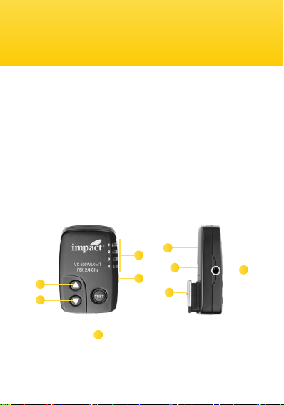
Setting the Flash Power Output
Press the up or down button on the remote to
adjust the power output of the monolight.
If the ash and modeling light are set to
“proportional” mode, the modeling light power will
increase or decrease proportionally to the ash
power output setting.
If the ash and modeling light are set to
“independent” mode, only the ash power will
increase or decrease. (Refer to the user manual
of the VC-500WL for instruction on how to change
modes.)
Setting the Modeling Light Power Output
1. Press and hold the up button to turn the
modeling light on. If the modeling light is
already on, press and hold the up button until
you hear a beep.
2. Within one second of the modeling light turning
on (or hearing the beep), quick-press the up
or down button to adjust the light’s power.

10
Specications VC-500WL
Frequency 2.4 GHz
Voltage DC 5V
Maximum Wireless Range 328 ft. (100 m)
Battery CR2032 3V
Synchronization Hot Shoe, or included 3.5mm - PC
Sync Cable
Sync cable length 12 in. (30 cm)
Dimensions 2.3 × 1.5 × 0.8 in. (6 × 4 × 2.1 cm)
Weight 1.6 oz. (45 g)
• Note: if there is more than a one-second delay
pressing the up or down buttons after the
modeling light has powered on, the power
output of the ash will change as described
above.
3. Press and hold the down button to turn the
modeling light off.
Testing the Monolight
1. Press the transmitter’s test button to test-re
the monolight.

11
FCC DISCLAIMER:
This device complies with Part 15 of the FCC rules.
Operation i ssubject to the following two conditions:
(1) this device may not cause harmful interference,
and (2) this device must accept any interference
received, including interference that may cause
undesired operation.
Made in China

GG3
One-Year Limited Warranty
This Impact product is warranted to the original purchaser to be free
from defects in materials and workmanship under normal consumer use
for a period of one (1) year from the original purchase date or thirty (30)
days after replacement, whichever occurs later. The warranty provider’s
responsibility with respect to this limited warranty shall be limited solely to
repair or replacement, at the provider’s discretion, of any product that fails
during normal use of this product in its intended manner and in its intended
environment. Inoperability of the product or part(s) shall be determined by
the warranty provider. If the product has been discontinued, the warranty
provider reserves the right to replace it with a model of equivalent quality
and function.
This warranty does not cover damage or defect caused by misuse, neglect,
accident, alteration, abuse, improper installation or maintenance. EXCEPT
AS PROVIDED HEREIN, THE WARRANTY PROVIDER MAKES NEITHER ANY
EXPRESS WARRANTIES NOR ANY IMPLIED WARRANTIES, INCLUDING
BUT NOT LIMITED TO ANY IMPLIED WARRANTY OF MERCHANTABILITY
OR FITNESS FOR A PARTICULAR PURPOSE. This warranty provides you
with specic legal rights, and you may also have additional rights that vary
from state to state.
To obtain warranty coverage, contact the Impact Customer Service
Department to obtain a return merchandise authorization (“RMA”)
number, and return the defective product to Impact along with the RMA
number and proof of purchase. Shipment of the defective product is at the
purchaser’s own risk and expense.
For more information or to arrange service, visit www.
impactstudiolighting.com or call Customer Service at 212-594-2353
Product warranty provided by the Gradus Group.
www.gradusgroup.com
Impact is a registered trademark of the Gradus Group.
© 2019 Gradus Group LLC. All Rights Reserved.
IMPACT
®
A Gradus Group Brand
Table of contents