Vega VEGADIF 85 User manual

Operating Instructions
Dierential pressure transmitter with
metallic measuring diaphragm
VEGADIF 85
Modbus and Levelmaster protocol
Document ID: 53571

2
Contents
VEGADIF 85 • Modbus and Levelmaster protocol
53571-EN-230814
Contents
1 About this document ............................................................................................................... 4
1.1 Function ........................................................................................................................... 4
1.2 Target group ..................................................................................................................... 4
1.3 Symbols used................................................................................................................... 4
2 For your safety ......................................................................................................................... 5
2.1 Authorised personnel ....................................................................................................... 5
2.2 Appropriate use................................................................................................................ 5
2.3 Warning about incorrect use............................................................................................. 5
2.4 General safety instructions............................................................................................... 5
2.5 Conformity........................................................................................................................ 5
2.6 NAMUR recommendations .............................................................................................. 6
2.7 Environmental instructions ............................................................................................... 6
3 Product description ................................................................................................................. 7
3.1 Conguration.................................................................................................................... 7
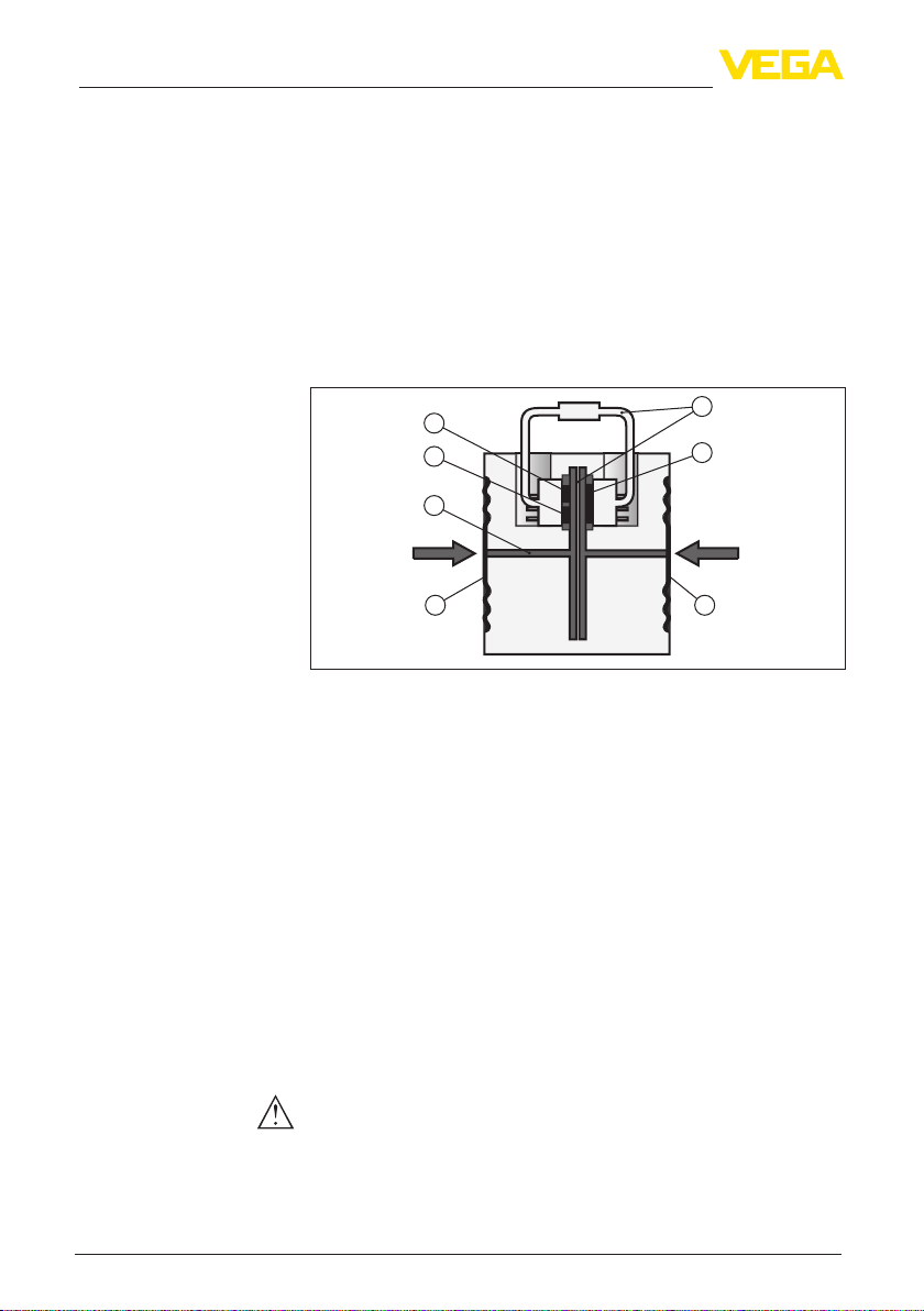
3.2 Principle of operation........................................................................................................ 8
3.3 Supplementary cleaning procedures.............................................................................. 10
3.4 Packaging, transport and storage................................................................................... 11
3.5 Accessories.................................................................................................................... 11
4 Mounting................................................................................................................................. 13
4.1 General instructions ....................................................................................................... 13
4.2 Instructions for oxygen applications ............................................................................... 15
4.3 Connection to the process.............................................................................................. 15
4.4 Mounting and connection instructions............................................................................ 16
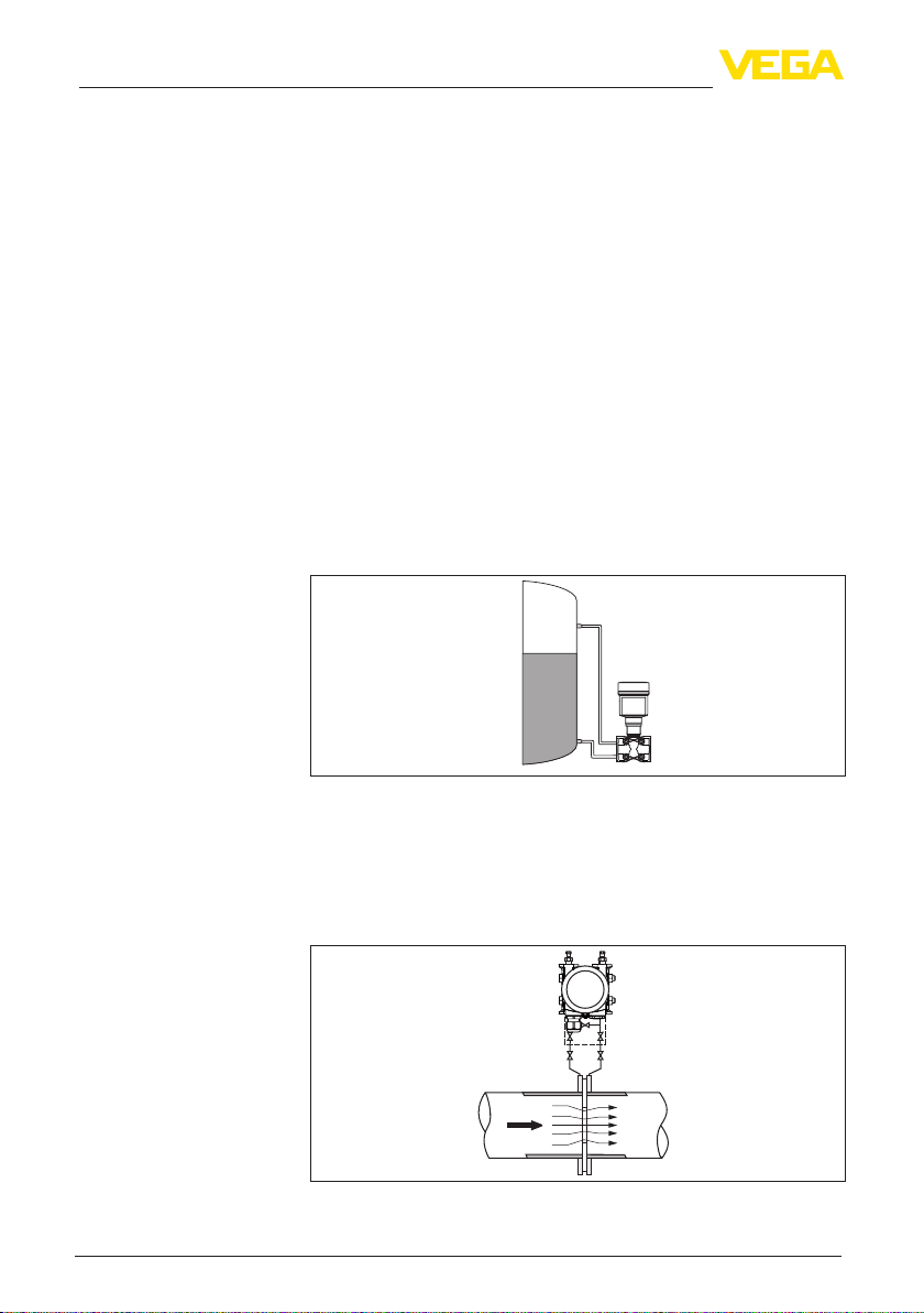
4.5 Measurement setups...................................................................................................... 18
5 Connecting to power supply and bus system .................................................................... 27
5.1 Preparing the connection ............................................................................................... 27
5.2 Connecting..................................................................................................................... 28
5.3 Wiring plan ..................................................................................................................... 30
5.4 External housing with version IP68 (25 bar) ................................................................... 31
5.5 Switch-on phase............................................................................................................. 33
6 Set up the sensor with the display and adjustment module............................................. 34
6.1 Insert display and adjustment module............................................................................ 34
6.2 Adjustment system......................................................................................................... 35
6.3 Measured value indication.............................................................................................. 36
6.4 Parameter adjustment - Quick setup .............................................................................. 37
6.5 Parameter adjustment - Extended adjustment................................................................ 37
7 Setting up sensor and Modbus interface with PACTware.................................................. 53
7.1 Connect the PC.............................................................................................................. 53
7.2 Parameterization ............................................................................................................ 54
7.3 Set instrument address .................................................................................................. 55
7.4 Save parameter adjustment data.................................................................................... 56
8 Set up measuring system ..................................................................................................... 57
8.1 Level measurement........................................................................................................ 57
8.2 Flow measurement......................................................................................................... 59
9 Diagnosis, asset management and service ........................................................................ 61
9.1 Maintenance .................................................................................................................. 61

3
Contents
VEGADIF 85 • Modbus and Levelmaster protocol
53571-EN-230814
9.2 Diagnosis memory ......................................................................................................... 61
9.3 Asset Management function........................................................................................... 62
9.4 Rectify faults................................................................................................................... 65
9.5 Replaceprocessanges................................................................................................ 65
9.6 Exchange process module on version IP68 (25 bar) ...................................................... 66
9.7 Exchanging the electronics module................................................................................ 67
9.8 Software update ............................................................................................................. 68
9.9 How to proceed if a repair is necessary.......................................................................... 68
10 Dismount................................................................................................................................. 69
10.1 Dismounting steps.......................................................................................................... 69
10.2 Disposal ......................................................................................................................... 69
11 Supplement ............................................................................................................................ 70
11.1 Technical data ................................................................................................................ 70
11.2 Device communication Modbus ..................................................................................... 79
11.3 Modbus register ............................................................................................................. 80
11.4 Modbus RTU commands ............................................................................................... 82
11.5 Levelmaster commands ................................................................................................. 85
11.6 CongurationoftypicalModbushosts ........................................................................... 88
11.7 Calculation of the total deviation..................................................................................... 88
11.8 Calculation of the total deviation - Practical example...................................................... 89
11.9 Dimensions, versions process component..................................................................... 90
11.10 Industrial property rights................................................................................................. 93
11.11 Trademark ...................................................................................................................... 93
Safety instructions for Ex areas:
TakenoteoftheExspecicsafetyinstructionsforExapplications.
These instructions are attached as documents to each instrument
with Ex approval and are part of the operating instructions.
Editing status: 2023-08-04

4
1 About this document
VEGADIF 85 • Modbus and Levelmaster protocol
53571-EN-230814
1 About this document
1.1 Function
This instruction provides all the information you need for mounting,
connection and setup as well as important instructions for mainte-
nance,faultrectication,safetyandtheexchangeofparts.Please
read this information before putting the instrument into operation and
keep this manual accessible in the immediate vicinity of the device.
1.2 Target group
This operating instructions manual is directed to trained personnel.
Thecontentsofthismanualmustbemadeavailabletothequalied
personnel and implemented.
1.3 Symbols used
Document ID
This symbol on the front page of this instruction refers to the Docu-
ment ID. By entering the Document ID on www.vega.com you will
reach the document download.
Information, note, tip: This symbol indicates helpful additional infor-
mation and tips for successful work.
Note: This symbol indicates notes to prevent failures, malfunctions,
damage to devices or plants.
Caution: Non-observance of the information marked with this symbol
may result in personal injury.
Warning: Non-observance of the information marked with this symbol
may result in serious or fatal personal injury.
Danger: Non-observance of the information marked with this symbol
results in serious or fatal personal injury.
Ex applications
This symbol indicates special instructions for Ex applications.
• List
The dot set in front indicates a list with no implied sequence.
1 Sequence of actions
Numbers set in front indicate successive steps in a procedure.
Disposal
This symbol indicates special instructions for disposal.

5
2 For your safety
VEGADIF 85 • Modbus and Levelmaster protocol
53571-EN-230814
2 For your safety
2.1 Authorised personnel
All operations described in this documentation must be carried out
only by trained and authorized personnel.
During work on and with the device, the required personal protective
equipment must always be worn.
2.2 Appropriate use
VEGADIF85isaninstrumentformeasurementofow,level,dieren-
tial pressure, density and interface.
Youcannddetailedinformationabouttheareaofapplicationin
chapter " Product description".
Operational reliability is ensured only if the instrument is properly
usedaccordingtothespecicationsintheoperatinginstructions
manual as well as possible supplementary instructions.
2.3 Warning about incorrect use
Inappropriate or incorrect use of this product can give rise to applica-
tion-specichazards,e.g.vesseloverllthroughincorrectmounting
or adjustment. Damage to property and persons or environmental
contamination can result. Also, the protective characteristics of the
instrument can be impaired.
2.4 General safety instructions
This is a state-of-the-art instrument complying with all prevailing
regulations and directives.The instrument must only be operated in
atechnicallyawlessandreliablecondition.Theoperatingcompany
is responsible for the trouble-free operation of the instrument.When
measuring aggressive or corrosive media that can cause a danger-
ous situation if the instrument malfunctions, the operating company
has to implement suitable measures to make sure the instrument is
functioning properly.
The safety instructions in this operating instructions manual, the
national installation standards as well as the valid safety regulations
and accident prevention rules must be observed.
For safety and warranty reasons, any invasive work on the device
beyond that described in the operating instructions manual may be
carried out only by personnel authorised by us. Arbitrary conversions
ormodicationsareexplicitlyforbidden.Forsafetyreasons,onlythe
accessoryspeciedbyusmustbeused.
To avoid any danger, the safety approval markings and safety tips on
the device must also be observed.
2.5 Conformity
The device complies with the legal requirements of the applicable
country-specicdirectivesortechnicalregulations.Weconrmcon-
formity with the corresponding labelling.

6
2 For your safety
VEGADIF 85 • Modbus and Levelmaster protocol
53571-EN-230814
The corresponding conformity declarations can be found on our
homepage.
2.6 NAMUR recommendations
NAMUR is the automation technology user association in the process
industry in Germany. The published NAMUR recommendations are
acceptedasthestandardineldinstrumentation.
ThedevicefullstherequirementsofthefollowingNAMURrecom-
mendations:
• NE 21 – Electromagnetic compatibility of equipment
• NE53–Compatibilityofelddevicesanddisplay/adjustment
components
• NE107–Self-monitoringanddiagnosisofelddevices
For further information see www.namur.de.
2.7 Environmental instructions
Protection of the environment is one of our most important duties.
That is why we have introduced an environment management system
with the goal of continuously improving company environmental pro-
tection.Theenvironmentmanagementsystemiscertiedaccording
to DIN EN ISO 14001.
Pleasehelpusfullthisobligationbyobservingtheenvironmental
instructions in this manual:
• Chapter " Packaging, transport and storage"
• Chapter " Disposal"

7
3 Product description
VEGADIF 85 • Modbus and Levelmaster protocol
53571-EN-230814
3 Product description
3.1 Conguration
The scope of delivery encompasses:
• VEGADIF 85 pressure transmitter
• Ventilation valves, closing screws – depending on version (see
chapter " Dimensions")
The further scope of delivery encompasses:
• Documentation
– Quick setup guide VEGADIF 85
– Testcerticateforpressuretransmitters
– Instructions for optional instrument features
– Ex-specic"Safety instructions" (with Ex versions)
– Ifnecessary,furthercerticates
Information:
Optional instrument features are also described in this operating
instructions manual.The respective scope of delivery results from the
orderspecication.
This operating instructions manual applies to the following instrument
versions:
• Hardware from 1.0.0
• Software from 1.3.4
Note:
Youcanndthehardwareandsoftwareversionoftheinstrumentas
follows:
• On the type plate of the electronics module
• In the adjustment menu under " Info"
Thetypelabelcontainsthemostimportantdataforidenticationand
use of the instrument:
• Instrument type
• Information about approvals
• Congurationinformation
• Technical data
• Serial number of the instrument
• QRcodefordeviceidentication
• Numerical code for Bluetooth access (optional)
• Manufacturer information
Tondorderdata,documentsorsoftwarerelatedtoyourdevice,you
have the following options:
• Move to " www.vega.com"andenterinthesearcheldtheserial
number of your instrument.
• Scan the QR code on the type label.
• Open the VEGA Tools app and enter the serial number under "
Documentation".
Scope of delivery
Scope of this operating
instructions
Type label
Documents and software

8
3 Product description
VEGADIF 85 • Modbus and Levelmaster protocol
53571-EN-230814
3.2 Principle of operation
VEGADIF 85 is suitable universally for applications in virtually all
industries. It is used for the measurement of the following pressure
types:
• Dierentialpressure
• Static pressure
Measured products are gases, vapours and liquids.
Thedierentialpressuremeasurementenablesthemeasurementof:
• Level
• Flow
• Dierentialpressure
• Density
• Interface
The instrument is suitable for level measurement in closed, superim-
posedpressurevessels.Thestaticpressureiscompensatedbydier-
ential pressure measurement. It is available as a separate measured
value for digital signal outputs.
Fig. 1: Level measurement with VEGADIF 85 in a pressurized vessel
Theowmeasurementiscarriedoutviaaneectivepressuretrans-
mitter,suchasanoriceplateorpitottube.Thedevicerecordsthe
resultingpressuredierenceandconvertsthemeasuredvalueinto
theow.Withdigitalsignaloutputs,thestaticpressureisavailableas
a separate measured value.
Q
p1p2
+–
Fig. 2: Flow measurement with VEGADIF 85 and orice, Q = ow, dierential
pressure Δp = p1- p2
Application area
Measured products
Measured variables
Level measurement
Flow measurement

9
3 Product description
VEGADIF 85 • Modbus and Levelmaster protocol
53571-EN-230814
Thepressuresintwodierentpipelinesareacquiredviaeective
pressurelines.Thedevicedeterminesthedierentialpressure.
+
p12
p
Fig. 3: Measurement of the dierential pressure in pipelines with VEGADIF 85,
dierential pressure Δp = p1- p2
With the help of the instrument, density measurement in a vessel with
changing level and homogeneous density distribution can be easily
realized.The instrument is connected to the vessel via a chemical
sealattwodierentmeasuringpoints.
+
–
Fig. 4: Density measurement with VEGADIF 85
The instrument can also be used for interface measurement in a ves-
sel with changing level. The instrument is connected to the vessel via
achemicalsealattwodierentmeasuringpoints.
+
–
Fig. 5: Interface measurement with VEGADIF 85
Dierentialpressure
measurement
Density measurement
Interface measurement

10
3 Product description
VEGADIF 85 • Modbus and Levelmaster protocol
53571-EN-230814
A metallic measuring cell is used as sensor element. The process
pressuresaretransmittedviatheseparatingdiaphragmsandlling
oils to a piezoresistive sensor element (resistance measuring bridge
using semiconductor technology).
Thedierencebetweentheactingpressureschangesthebridgevolt-
age.This change is measured, further processed and converted into
a corresponding output signal.
When measurement limits are exceeded, an overload system protects
the sensor element against damage.
In addition, the measuring cell temperature and the static pressure
are measured on the low pressure side.The measuring signals are
further processed and are available as additional output signals.
P P
5
4
66
3
2
1
Fig. 6: Conguration metallic measuring cell
1 Filling uid
2 Temperature sensor
3 Absolute pressure sensor, static pressure
4 Overload system
5 Dierential pressure sensor
6 Separating diaphragm
3.3 Supplementary cleaning procedures
The VEGADIF 85 is also available in the version " Oil, grease and
silicone-free".These instruments have passed through a special
cleaning procedure to remove oil, grease and paint-wetting impair-
ment substances (PWIS).
The cleaning is carried out on all wetted parts as well as on surfaces
accessible from outside.To keep the purity level, the instruments are
immediately packed in plastic foil after the cleaning process.The
purity level remains as long as the instrument is kept in the closed
original packaging.
Caution:
The VEGADIF 85 in this version may not be used in oxygen applica-
tions. For this purpose, instruments are available in the special ver-
sion " Oil, grease and silicone-free for oxygen applications".
Functional principle

11
3 Product description
VEGADIF 85 • Modbus and Levelmaster protocol
53571-EN-230814
3.4 Packaging, transport and storage
Your instrument was protected by packaging during transport. Its
capacity to handle normal loads during transport is assured by a test
based on ISO 4180.
The packaging consists of environment-friendly, recyclable card-
board. For special versions, PE foam or PE foil is also used. Dispose
of the packaging material via specialised recycling companies.
Caution:
Instruments for oxygen applications are sealed in PE foil and provided
with a label "Oxygen! Use no Oil". Remove this foil just before mount-
ing the instrument! See instruction under " Mounting".
Transport must be carried out in due consideration of the notes on the
transport packaging. Nonobservance of these instructions can cause
damage to the device.
The delivery must be checked for completeness and possible transit
damage immediately at receipt. Ascertained transit damage or con-
cealed defects must be appropriately dealt with.
Up to the time of installation, the packages must be left closed and
stored according to the orientation and storage markings on the
outside.
Unless otherwise indicated, the packages must be stored only under
the following conditions:
• Not in the open
• Dry and dust free
• Not exposed to corrosive media
• Protected against solar radiation
• Avoiding mechanical shock and vibration
• Storage and transport temperature see chapter " Supplement -
Technical data - Ambient conditions"
• Relative moisture 20 … 85 %
With instrument weights of more than 18 kg (39.68 lbs) suitable and
approved equipment must be used for lifting and carrying.
3.5 Accessories
The instructions for the listed accessories can be found in the down-
load area on our homepage.
The display and adjustment module is used for measured value indi-
cation, adjustment and diagnosis.
The integrated Bluetooth module (optional) enables wireless adjust-
ment via standard adjustment devices.
The interface adapter VEGACONNECT enables the connection of
communication-capable instruments to the USB interface of a PC.
Packaging
Transport
Transport inspection
Storage
Storage and transport
temperature
Lifting and carrying
Display and adjustment
module
VEGACONNECT

12
3 Product description
VEGADIF 85 • Modbus and Levelmaster protocol
53571-EN-230814
The VEGADIS adapter is an accessory part for sensors with double
chamber housing. It enables the connection of VEGADIS 81 to the
sensor housing via an M12 x 1 plug.
The protective cover protects the sensor housing against soiling and
intense heat from solar radiation.
The suitable mounting accessories for VEGADIF 85 include oval
angeadapters,valveblocksaswellasmountingbrackets.
Through the use of chemical seals, VEGADIF 85 can also be used for
corrosive, highly viscous or hot media.
VEGADIS adapter
Protective cover
Mounting accessories
Chemical seal

13
4 Mounting
VEGADIF 85 • Modbus and Levelmaster protocol
53571-EN-230814
4 Mounting
4.1 General instructions
Note:
For safety reasons, the instrument must only be operated within the
permissibleprocessconditions.Youcannddetailedinformationon
the process conditions in chapter " Technical data" of the operating
instructions or on the type label.
Hence make sure before mounting that all parts of the instrument ex-
posed to the process are suitable for the existing process conditions.
These are mainly:
• Active measuring component
• Processtting
• Process seal
Process conditions in particular are:
• Process pressure
• Process temperature
• Chemical properties of the medium
• Abrasionandmechanicalinuences
Thepermissibleprocesspressurerangeisspeciedonthetypelabel
with "MWP" (Maximum Working Pressure), see chapter " Congura-
tion".Thisspecicationreferstoareferencetemperatureof+25°C
(+76°F).TheMWPmayalsobepermanentlyappliedononeside.
In order to prevent damage to the device, a test pressure acting on
bothsidesmayonlyexceedthespeciedMWPbrieyby1.5times
atreferencetemperature.Thepressurestageoftheprocessttingas
well as the overload resistance of the measuring cell are taken into
consideration here (see chapter " Technical Data").
Inaddition,atemperaturederatingoftheprocesstting,e.g.with
angeisolatingdiaphragms,canlimitthepermissibleprocesspres-
sure range according to the respective standard.
Protect your instrument against moisture ingress through the following
measures:
• Use a suitable connection cable (see chapter " Connecting to
power supply")
• Tighten the cable gland or plug connector
• Lead the connection cable downward in front of the cable entry or
plug connector
This applies mainly to outdoor installations, in areas where high
humidity is expected (e.g. through cleaning processes) and on cooled
or heated vessels.
Note:
Make sure that during installation or maintenance no moisture or dirt
can get inside the instrument.
Process conditions
Permissible process
pressure (MWP)
Protection against mois-
ture

14
4 Mounting
VEGADIF 85 • Modbus and Levelmaster protocol
53571-EN-230814
To maintain the housing protection, make sure that the housing lid is
closed during operation and locked, if necessary.
Theventilationfortheelectronicshousingisrealisedviaalterele-
ment in the vicinity of the cable glands.
1 2 3
6
6
6 6
6
5
4
Fig. 7: Position of the lter element - non-Ex, Ex-ia and Ex-d-ia version
1 Plastic, stainless steel single chamber (precision casting)
2 Aluminium - single chamber
3 Stainless steel single chamber (electropolished)
4 Plastic double chamber
5 Aluminium, stainless steel double chamber housing (precision casting)
6 Filter element
Information:
Makesurethatthelterelementisalwaysfreeofbuildupduringop-
eration. A high-pressure cleaner may not be used for cleaning.
For better readability of the display or access to the wiring, the elec-
tronicshousingcanberotatedby330°.Astoppreventsthehousing
from being turned too far.
Depending on the version and housing material, the locking screw on
the neck of the housing must be slightly loosened. The housing can
then be turned to the correct position. As soon as the requested posi-
tion is reached, tighten the locking screw.
Higher process temperatures often mean also higher ambient
temperatures. Make sure that the upper temperature limits stated in
chapter " Technical data" for the environment of the electronics hous-
ing and connection cable are not exceeded.
Ventilation
Turning the housing
Temperature limits

15
4 Mounting
VEGADIF 85 • Modbus and Levelmaster protocol
53571-EN-230814
4.2 Instructions for oxygen applications
Warning:
Asanoxidisingagent,oxygencancauseorintensifyres.Oils,
grease, some plastics and dirt can burn explosively on contact with
oxygen.There is a risk of serious personal injury or damage to prop-
erty.
Therefore, to avoid this, take the following precautions, for example:
• All components of the system - measuring instruments - must
be cleaned in accordance with the requirements of recognized
regulations or standards
• Depending on the seal material, certain temperatures and pres-
sures must not be exceeded in oxygen applications, see chapter "
Technical data"
• Devices for oxygen applications may only be unpacked from the
PE foil just before assembly.
• Checkwhetherthemarking"O2"isvisibleontheprocesstting
afterremovingtheprotectionfortheprocesstting
• Avoid any ingress of oil, grease and dirt
4.3 Connection to the process
DPowelementsareinstallationsinpipelineswhichgeneratea
ow-dependentpressuredrop.Theowrateismeasuredviathisdif-
ferentialpressure.TypicalDPowelementsareVenturitubes,orice
plates or impact pressure probes.
InstructionsformountingtheDPowelementsarestatedintheap-
propriate standards as well as in the documentation from the respec-
tive manufacturer.
Eectivepressurelinesarepipelineswithasmalldiameter.Theyare
usedtoconnectthedierentialpressuretransmittertothepressure
tappingpointortheDPowelement.
Principles
Eectivepressurelinesforgasesmustalwaysremaincompletelydry
andnocondensatemustcollect.Eectivepressurelinesforliquids
mustalwaysbecompletelylledandmustnotcontainanygasbub-
bles.Therefore, suitable venting systems must be provided for liquids
and suitable drainage systems for gases.
Wiring
Eectivepressurelinesmustalwaysrunwithasucient,strictlymo-
notonousslope/gradientofatleast2%,butbetterupto10%.
Recommendationsforwiringofeectivepressurelinesarestatedin
the corresponding national and international standards.
Connection
Eectivepressurelinesareconnectedtothedeviceviastandardcut-
ting ring screw connections with suitable thread.
DPowelement
Eectivepressurelines

16
4 Mounting
VEGADIF 85 • Modbus and Levelmaster protocol
53571-EN-230814
Note:
Follow the mounting instructions of the respective manufacturer and
seal the thread, e.g. with PTFE tape.
Valveblocksareusedforinitialshut-owhenconnectingthedier-
ential pressure transmitter to the process.They are also used for pres-
sure compensation of the measuring chambers during adjustment.
3-fold and 5-fold valve blocks are available (see chapter " Mounting
and connection instructions").
Free openings on the process assembly must be closed by ventilation
valves or closing screws. Required torque see chapter " Technical
data".
Note:
Use the supplied parts and seal the thread with four layers of PTFE
tape.
4.4 Mounting and connection instructions
When connecting VEGADIF 85 to the measuring point, take note of
thehigh/lowpressuresideoftheprocesscomponent.1).
The " H"identiesthehighpressureside,thelowpressuresidedue
to an " L"ontheprocesscomponentnexttotheovalanges.
Note:
The static pressure is measured on the low pressure side " L".
2
1
H L
Fig. 8: Marking for high/low pressure side on the process component
1 H = High pressure side
2 L = Low pressure side
Valve blocks
Ventilation valves, closing
screws
Connection high/low
pressure side
1) Thepressureeectiveon"H"isconsideredaspositive,thepressureeec-
tiveon"L"asnegativeinthecalculationofthepressuredierence.

17
4 Mounting
VEGADIF 85 • Modbus and Levelmaster protocol
53571-EN-230814
A:
A
2 2
1
3 45
Fig. 9: Connection of a 3-fold valve block
1 Process tting
2 Process tting
3 Inlet valve
4 Inlet valve
5 Breather valve
A:
A
2 2
13 45
Fig. 10: Connection of a 3-fold valve block, anging on both sides
1 Process tting
2 Process tting
3 Inlet valve
4 Inlet valve
5 Breather valve
3-fold valve block
3-foldvalveblock,ang-
ing on both sides

18
4 Mounting
VEGADIF 85 • Modbus and Levelmaster protocol
53571-EN-230814
Note:
Nomountingbracketisrequiredforvalveblocksthatcanbeange-
mounted on both sides.The process side of the valve block is
mounteddirectlytoaDPowelement,e.g.anoriceplate.
A:
A
2 2
1
4
7
3 5
6
Fig. 11: Connection of a 5-fold valve block
1 Process tting
2 Process tting
3 Inlet valve
4 Breather valve
5 Inlet valve
6 Valve for checking/ventilating
7 Valve for checking/ventilating
4.5 Measurement setups
4.5.1 Overview
The following sections show common measurement setups:
• Level
• Flow
• Dierentialpressure
• Interface
• Density
Dependingontheapplication,theremayalsobedierentarrange-
ments.
Note:
Forsimplication,theeectivepressurelinesarepartlyshownwith
a horizontal course and sharp angles. For wiring, please observe the
instructions in chapter " Mounting, Connection to the process" as well
5-fold valve block

19
4 Mounting
VEGADIF 85 • Modbus and Levelmaster protocol
53571-EN-230814
as the hook ups in the supplementary instructions " Mounting acces-
sory pressure technology".
4.5.2 Level
• Mount device below the lower measurement connection so that
theeectivepressurelinesarealwayslledwithliquid
• Always connect the low pressure side above the max. level in the
vessel
• For measurement in products with solid content, such as e.g. dirty
liquids, the installation of separators and drain valves is recom-
mended. Debris and sediment can thus be collected and removed.
+
–
min.
max.
1
3
4
3
4
5
2
1
Fig. 12: Measurement setup, level measurement in closed vessel
1 Blocking valves
2 3-fold valve block
3 Precipitator
4 Drain valves
5 VEGADIF 85
• Mount device directly to the vessel
• Always connect the low pressure side above the max. level in the
vessel
• For measurement in products with solid content, such as e.g. dirty
liquids, the installation of separators and drain valves is recom-
mended. Debris and sediment can thus be collected and removed.
In closed vessels with ef-
fective pressure lines
In closed vessels with
single chemical seal

20
4 Mounting
VEGADIF 85 • Modbus and Levelmaster protocol
53571-EN-230814
+
–
max.
min.
1
2
3
4
Fig. 13: Measurement setup, level measurement in closed vessel
1 Blocking valve
2 Precipitator
3 Drain valve
4 VEGADIF 85
• Mount device below the lower chemical seal
• The ambient temperature should be the same for both capillaries
Information:
Level measurement is only carried out between the upper edge of the
lower and the lower edge of the upper chemical seal.
+
–
min.
max.
1
Fig. 14: Measurement setup, level measurement in closed vessel
1 VEGADIF 85
• Mount device below the lower measurement connection so that
theeectivepressurelinesarealwayslledwithliquid
• Always connect the low pressure side above the max. level in the
vessel
• The condensate vessel ensures a constant pressure on the low
pressure side
• For measurement in products with solid content, such as e.g. dirty
liquids, the installation of separators and drain valves is recom-
mended. Debris and sediment can thus be collected and removed.
In closed vessels with
double chemical seal
In closed vessels with
steamlayeringwitheec-
tive pressure line
Other manuals for VEGADIF 85
5
Table of contents
Other Vega Transmitter manuals

Vega
Vega VEGADIF 65 User manual

Vega
Vega VEGADIF 85 User manual

Vega
Vega VEGABAR 83 User manual

Vega
Vega VEGABAR 86 User manual

Vega
Vega VEGABAR 81 User manual

Vega
Vega VEGABAR 82 User manual

Vega
Vega VEGABAR 82 User manual

Vega
Vega VEGAPULS 62 User manual

Vega
Vega VEGABAR 82 User manual

Vega
Vega VEGABAR S 14 User manual

Vega
Vega VEGABAR 52 User manual

Vega
Vega VEGABAR 86 User manual

Vega
Vega VEGABAR 82 User manual

Vega
Vega VEGABAR 53 User manual

Vega
Vega VEGABAR 81 User manual

Vega
Vega VEGABAR 83 User manual

Vega
Vega VEGAWELL 52 User manual

Vega
Vega VEGABAR 86 User manual

Vega
Vega VEGABAR 83 User manual

Vega
Vega VEGABAR 17 User manual