Tarot ZYX-5D User manual

5
V1.00
2015.3.16 User Manual
Thanks for your purchase of Tarot professional aerial photography products .
To ensure your success with this product, we would like to introduce the foll-
owing information and important notes ,hope it can be useful for you .

Warning and Disclaimer . .... .. .. .. .. .. .. .. .. .. .. .. .. .. .. .. . 2
Product Introduction .. .. .. .. .. .. .. .. .. .. .. .. .. .. .. .. .. .. .. . 3
A. Product List .. .. .. .. .. .. .. .. .. .. .. .. .. .. .. .. .. .. .. .. . 4
1. Package Contents .. .. .. .. .. .. .. .. .. .. .. .. .. .. .. .. . 4
2. Self-prepared ......................................4
B. Mounting and Conguration................................ 5
1. Camera Setup .................................... 5
2. Gimbal Mounting .. .. .. .. ..。. .. .. .. .. .. .. .. .. .. .. .. 6-7
3. Camera Connection and Camera Control ................ 8
4. Video Signal Transmission...............。.............9
5. Gimbal Controller Connection .. .. .. .. .. .. .. .. .. ...... 10
6. Gimbal Working Mode............................11-12
C.Flight Test...........................................13
D.ZYX-5D Assistant Software ............................ 14
1. Drive & PC Assistant Software Installation and Setup .. .. .. .. .. 14
2. Introduction .......................................14
3. Basic Setup .. .. .. .. .. .. .. .. .. .. .. .. .. .. .. .. .. .. .. .1 5
4. Channel Descriptions ................................ 16
5. Tools ............................................17
6. Firmware Upgrade . .. .. .. .. .. .. .. .. .. .. .. .. .. .. .. .. .17
E.Troubleshooting . .. .. .. .. .. .. .. .. .. .. .. .. .. .. .. .. .. .. .. 18
F.Specications.. .. .. .. .. .. .. .. .. .. .. .. .. .. .. .. .. .. .. .. 19
G.Port Descriptions. . . . . . . . . . . . . . . . . . . . . . . . . . . . . . . . . . . . . 20
H.LED Indicator.. .. .. .. .. .. .. .. .. .. .. .. .. .. .. .. .. .. .. .. .21
Contents
ASSEMBLY SECTION
1
5

2
Warning and Disclaimer
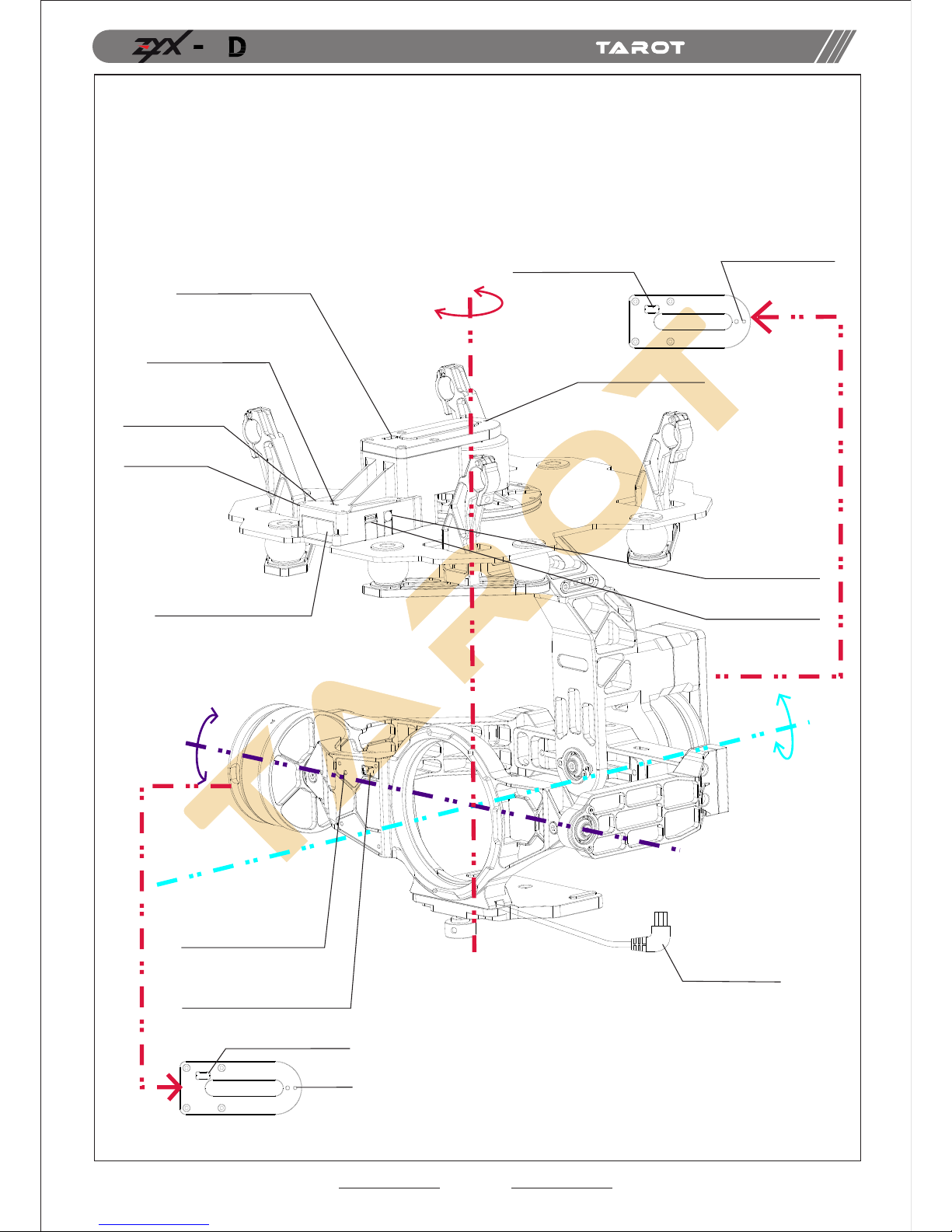
Please DO NOT adjust the gimbal or change its mechanical structure!
Specied Camera and Lens:
Camera:Canon 5D MARK III
Lens:Canon EF 17-40mm f/4L USM
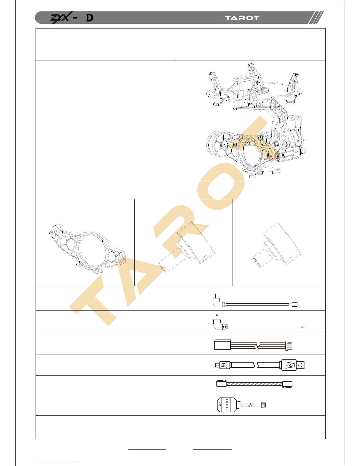
ASSEMBLY SECTION
5
Before leaving the factory, ZYX-5D gimbal has been adjusted to t the
camera and lens. Based on the setup procedures, you can achieve a
fabulous ight experience. Please do not adjust the gimbal or change
its mechanical structure. Moreover, do not add any component, such
as a lter or lens hood, to the camera. It is highly suggested to apply to
the original battery to avoid malfunctions of internal wirings or perform-
ance degradations.
In order to ensure the safety of ight control system after powering up,
we recommend you to remove all the propellers and usenon-power-supply
for the gimbal. Keep the entire components far from children!
Because we have no control of the use, mounting, assembly and modicat-
ion processes, TAROT will not assume any legal responsibility for the injury
or damage.
The state intellectual property has been awarded the TAROT model.,ltd five patents. Any units orindividual
Warning
警 告
国家知 识 产 权 已授予TARO T航 模 有限公司此产 品 五 项专利权.任何单 位 或 个 人未经持有 者 授 权 许可,制造、 仿
专利 号p ate n t num ber : 2 0 142 015 4 657 9
专利 号p ate n t num ber : 2 0 142 015 4 658 3
专利 号p ate n t num ber : 2 0 142 015 4 659 8
专利 号p ate n t num ber : 2 0 143 007 4 158 1
without the license holder manufacture 、copy 、use and sale the product will be patent lawsuit.
造、使 用 、 销 售此产品将 会 面 临 专利侵权诉讼.

3
Product Introduction
360°
±25°
-120°~+15°
TILT
ROLL
PAN
Roll Motor Drive
Module Indicator
Roll Motor Dirve
Module Upgrade Port
ASSEMBLY SECTION
5
ZYX-5D, a great gimbal for model aircraft enthusiasts, can be widely applied to
various model aircraft activities and entertainments. With unique internal wiring
design, built-in IMU gimbal control module, specialized servo drive module, this
gimbal is able to support three working modes, including Attitude Lock(AL) mode,
Pan Follow (PF) mode and First Person View (FPV) mode.
Pan Motor Drive
Module Indicator
Pan Motor Drive Module
Upgrade Port
Av Port
Gimbal Controller
Upgrade Port
Video Transmission
Cable To 5d MarkIII
Tilt Motor Drive Module Upgrade Port
Tilt Motor Drive Module Indicator
Sensor Module
Indicator(blue)
Sensor Module Upgrade Port
Receiver/ight Control Port
Gimbal Controller Indicator
Power Line
Satellite Receiver Pot

4
A.Product List
1. Package Contents
2. Self-prepared
Main Components Pack
Gimbal*1
Lens RetainingPlate*1 Lens RetainingScrew* Camera Mounting Screws*
Video Transmission Cable*1
AV Cable*1
Gimbal to Flight Control Cable
USB Cable*1
Canon 5D M AR K II I Ca me ra *1,C anon EF 17-40mm f /4 L US M Le ns *1
Multi- ro to r* 1,RX/TX.
Cable *5
USB module *1
ASSEMBLY SECTION
5
With unique internal wiring design,
built-in IMU gimbal control module,
specialized servo drive module, this
gimbal is able to support three
working modes, including Attitude
Lock (AL) mode, Pan Follow (PF)
mode and First Person View(FPV) mode.

5
B.Mounting and Conguration
1. Camera Setup
①Set your camera to Tv (Shutter-Priority AE) or M (Manual Exposure).
②Turn (Live View shooting/Movie shooting Switch)to (Live View).
③Press the button “AF.DRIVE”,set the drive mode to (2-sec-self.timer/
remotecontrol)or (10-sec-self.timer/remote control).
TIPs:
①In Manual Exposure, please set the ISO to Auto.
②Please adjust the shutter speed between 1/100 and 1/30 seconds. With
manual exposure, please adjust the aperture to your preferences and set ISO to A.
2. Gimbal Mounting
(1)Lens Mounting
ASSEMBLY SECTION
5
Please mount the lens into the xing ring, and then mount the
lens onto the camera.
Lens Lens Retaining
Plate Camera

6
(2)Camera Mounting
①Mount the camera into the gimbal.
②Tighten up the camera mounting screw.
③Tighten up the lens retaining plate screw.
Attention: Please screw down both screws, otherwise vibrations might occur.
ASSEMBLY SECTION
5
Camera Mounting Screw
Lens Retaining Plate Screw

7
96°
165 mm
(155 mm)
240 mm
180°
(3)Gimbal Mounting
Mount the gimbal onto the landing gear. With some thread locker,
tighten the mount screws.
TIPs:
①Please DO NOT remove any screw in the gimbal during mounting.
②We have correctly adjusted the center of gravity of the gimbal. Please
DO NOT change it based on your preference.
③The controller module with pin-port side should face to the head of the
multi-rotor.
④When mounting the gimbal and landing gear, please ensure all the dampen
components are paralleled and undamaged.
⑤Please make sure all the wirings are correct.
ASSEMBLY SECTION
5

8
3.Camera Connection and Camera Control
Camera Connection
Attentions:
Ensure that you have set the drive mode to (2-sec-self.timer/remote
control) or
Camera Control
ZYX-5D gimbal is able to transfer the transmitter signal to camera
control signal. You can achieve remote shutter control through a
switch on the transmitter.
PHOTOS
RECORDING
Position 2→Position 1
Position 2→Position 3
Position 1→Position 2
Position 3→Position 2
Position 2→Position 1
Position 2→Position 3
Take a photo
Start recording
Centered (no action)
centered (no action)
Take another photo
Stop recording
ASSEMBLY SECTION
5
ZYX-5D gimbal is able to transfer the transmitter signal to infrared signal.
Please ensure the connection and setup between camera and gimbal are
correct.
Connect the gimbal video transmission cable to the A/V OUT/DIGITAL
port of the camera.
(10-sec-self.timer/remote control).
No matter which switch you have chosen, please ensure the connection
between receiver and PVC channel of gimbal controller. Toggle the switch
once, the camera will take a photo or start recording.

9
Attentions:
4. Video Signal Transmission
Attention:
①Please ensure the wireless video transmission module and gimbal controller
module has connected.
②Please use the standard AV cable, make sure the solder procedures are correct
and the cables are insulated without short circuit.
③Choose an external battery for the transmission module.
If you want to control the camera through a 2-position switch.
Please set your transmitter and observe the cursor of PVC
channel in the assistant software. Either taking-photos or
recording can be applied in this circumstance.
You should prepare a wireless video transmission module and connect the
cables according to the diagram below.
Step One: Solder Power/Video Signal/Ground Cable to the Wireless Video
Transmission Module.
Step Two: Connect the other side of the gimbal AV cable to the video signal
port of gimbal controller module.
ASSEMBLY SECTION
5

5
AV
DATA
PWR DSM
CH1
CH2
CH3
CH4
CH5
CH6
CH7
CH8
CH1
CH2
CH3
CH4
CH5
CH6
CH7
CH8
RX
TX
GND
SIGNAL
5V
GND
5.Gimbal Controller Connection
XT60
10
ASSEMBLY SECTION
5
Pan Motor Drive
Module Indicator
Av Port
Gimbal Controller
Upgrade Port
Gimbal Cotroller
Indicator
Pan Motor Drive
Module Upgrade Port
Power Line
Satellite Receiver
Port
Receiver/igh
Control Port

11
TIPs:
Battery
Receiver
Video
Flight Control
6. Gimbal Working Mode
ASSEMBLY SECTION
5
Power Supply:3S-6S Li (11V-26V)
* If you choose a battery to power up the gimbal and
multi-rotor, please make sure this battery meets
requirements of both components.
1. Common Receiver: connect the corresponding port of
common receiver to CHI-CH7 channels of gimbal controller.
Set related parameters in RECEIVER TYPE and RC
MAPPING in assistant software.
2. FutabaSBUS Receiver/ SBUS-2 Receiver: connect
SBUS receiver to CH7 channel of gimbal controller. Set
related parameters in RECEIVER TYPE and RC MAPPING
in assistant software.
3. Satellite Receiver: connect Satellite receiver to DSM
port of gimbal controller. Set related parameters in
RECEIVER TYPE and RC MAPPING in assistant software.
If binding is not successful in DSM2-1 or DSMX-1,
please choose DSM2-2 or DSMX-2 to bind.
Connect the wireless video transmission module to AV
port through a 3.5mm AV cable.
Gimbal can work without Tarot Multi-rotor Flight Control
Module, but the performance might be inuenced:
1. Angle offset might occur when the accelerated state lasts
for a long time.
2. In AL Mode, drifts might occur in pan angle due to gyro offset.
If you are pursuing a perfect performance, please connect the
gimbal and Tarot Multi-rotor Flight Control Module to the CH8
channel of gimbal controller.
You should select a three-positioned switch in the transmitter for working
mode. Please connect the corresponding port of the receiver to any
channel ofCH1-CH7channels of the gimbal controller.Set RC MAPPING
in the assistant software. For different positions, use endpoint ne tune
function to set. Please refer to the MODE Channel section in assistant
software for detailed information.

12
TIPs:
Descriptions:
Working Mode
Attitude Lock
(AL)Mode
Pan Follow
(PF)Mode First Person View
(FPV)Mode
Descriptions
The angles of Roll,
Pitch and Pan keep
unchanged.
The angles of Roll
and Pitch keep
unchanged, while
the angle of Pan
axis changes
according to the
head of the
multi-rotor.
The angles of Roll,
Pitch and Pan axis
change according to
the attitude of the
multi-rotor.
Tx Control Under Control Under Control Under Control
Attitude
Stability
Vibrat ion
Reduction
Working Mode setup:
Position 1 and Position 3 can be exchanged:
Choose a three-positioned switch:
Mode
ASSEMBLY SECTION
5
When the MODE port is unconnected, the gimbal can only work in the
DEFAULT mode. Moreover, during ight, if the MODE is unconnected
suddenly, the working mode would remain the same before disconnection.
After powering up the gimbal, if the receiver is unconnected, it works on
DEFAULT MODE.
Position 1 refers to FPV Mode; Position 2 corresponds to PF Mode;
Position 3 corresponds to AL Mode.
②Choose a two-positioned switch:
Only two working mode is available: please refer to the cursor position
of MODE Channel in the assistant software of detailed information.
√
√
√
√
√
√

13
C.Flight Test
Steps:
1.Please ensure all the wirings are correct and the power supply is in
great condition.
2. Turn on the transmitter.
3. Powering up the gimbal and keep it still. After self-check,gimbal angle
corresponds to INIT ANGLE in the assistant software.
4. Switch from different working modes to check the rotation direction in
ROLL, PITCH, and PAN axis.
TIPs:
Before ight test, please ensure:
1.Correctly mount the camera into the gimbaland the gimbal onto the
landing gear.
2. All the wirings are correct.
3. The camera and transmitter have correctly set.
Gimbal Self-check:
1. After powering up the gimbal, it enters self-check procedure. When RED,
YELLOW, BLUE lights ash, self-check nishes.
2. After self-check process nishes, gimbal angles corresponds to INIT
ANGLE in the assistant software.
ASSEMBLY SECTION
5

14
D.ZYX-5D Assistant Software
1. Drive & PC Assistant Software Installation and Setup
2. Introduction
①Please download the assistant software ZYX5D from http://www.0577mx.com/
②Run the drive program in USB Driver folder and nish the installation procedures
step by step. Please DO NOT ignore this step!
Windows x86: “CP210xVCPInstaller_x86.exe”;
Windows x64: “CP210xVCPInstaller_x64.exe”;
③Connect the USB module to the computer, and nish the installation.
④Run the assistant software ZYX5D.EXE and set the parameters.
ASSEMBLY SECTION
5
ZYX-5D, the three-axis gimbal, could support the camera to stabilize its
positions on the roll, tilt and pan axis.
You could adjust receiver type, working mode, angle range and other
options in the assistant software.
First of all, please connect gimbal controller to the PC through a USB
cable. Choose a correct COM port and click the “Connect”.
If the connection is successful, the gimbal would stop rotating to protect
your device.
After nish parameters setup, click “Run Gimbal”. Push sticks and toggle
switches to ensure the gimbal works correctly.
When nish parameters setup, you should click "Write Flash" to ensure all
the parameters have written to the gimbal. Moreover, the gimbal will
automatically run the parameters you have saved in the ash next time.

15
3. Basic Setup
1.Receiver Unconnected: set gimbal mode in Default
Mode of assistant software.
2. Receiver Connected: set gimbal mode in MODE
channel of the receiver.
FPV Mode: The direction of the gimbal and directions
(roll, tilt and pan) of the multi-rotor are the same.
PFMode:The head of the multi-rotor and the gimbal
are in the same direction.
AL Mode:The gimbal keeps a xed angle.
Init Angle stands for the initial angle of each direction
after the gimbal has been powered up. For instance,
if you want the tilt direction of the camera is on -45
degree, you should enter -45 on the corresponding box.
Angle Range of Roll:-25°~25°
Angle Range of Tilt:-120°~15°
Angle Range of Pan:-125°~125°
Please press “ENTER” button after modifying the parameters.
Angle Range of Rotation on each Direction
of the Gimbal.
If the gimbal rotates to or over the extreme
value, it would stop rotating until the value
goes within the range.
The Extreme Range of Roll:-25°~25°
The Extreme Range of Tilt:-120°~15
The Extreme Range of Pan:-125°~125°
Please press “ENTER” button after
modifying the parameters.
The maximum rotation speed the
gimbal can reach.
When pushing sticks to the maximum but
the rotation speed is lower, you could
increase the value of Max Rotation Speed
to enhance the rotation speed;
When pushing sticks gradually but the
rotation speed is too fast, you could
decrease the value to slow down the speed.
Max Rotation Speed Range of
ROLL: 0~200(degree/sec)
Max Rotation Speed Range of
TILT:0~200(degree/sec)
Max Rotation Speed Range of
PAN:0~200(degree/sec)
Please press “ENTER” button after
modifying the parameters.
Methods to Connect the Receiver:
Common Receiver: respectively connect to CH1-CH7
channel through 3P cables.
SBUS Receiver: Connect to CH7 channel
through a 3P cable.
Satellite Receiver: connect to the satellite
receiver DSM port.
Methods to control gimbal rotation by Tx (roll and tilt only):
Rate Mode: The position of the stick is corresponding to
the rotate speed of the gimbal.
Angle Mode: The position of the stick is corresponding to
the angle of the gimbal.
It relates to the response speed of the gimbal.When it
becomes too small, the stabilitydeteriorates. When it
turns too large, self-oscillation occurs.
Methods to adjust: if vibration occurs, please decrease
the parameters until it disappears.
Input Range: 0~200
Please press “ENTER” button after modifying
the parameters.
Attention: it has been adjusted to an appropriate value
before leaving factory. If vibrations do not occur, please
do not modify this value.
ASSEMBLY SECTION
5

16
4. Channel Descriptions
(1)Roll Channel
(2)Tilt Channel
(3)Pan Channel
(4)Mode Channel
(5)PVC Channel
(6)AUX通道
This channel controls gimbal working mode. Choose a three-position switch to control
the working mode of the gimbal
FPV Mode: the direction of the gimbal and directions (roll, tilt and pan) of the multi-rotor are same
PF Mode: the head of the multi-rotor and the gimbal are in the same direction.
AL Mode: keep a xed angle.
Observe the MODE channel:Toggle the switch to the position, the cursor should be in
the corresponding area.
1. This channel controls the camera to take photos and record. Please choose a
three-positioned channel to map to PVC channel.
2.Toggle the switch once, the camera would take a photo or start recording.
PI Mode: switch to this mode for one time, the camera would take a photo.
VI Mode:switch to this mode for one time, the camera would start/stop recording.
Observe PVC channel Toggle the switch to the position, the cursor should be in
the corresponding area.
Reserve Channels
Observe the rotation of the roll axis.
Push the stick, and observe the rotation
direction of the gimbal and the moving
direction of the cursor.
Observe the rotation of the tilt axis.
Push the stick, and observe the rotation
direction of the gimbal and the moving
direction of the cursor.
Observe the rotation of the pan axis.
Push the stick, and observe the rotation
direction of the gimbal and the moving
direction of the cursor.
ASSEMBLY SECTION
5

17
5. Tools
6. Firmware Upgrade
Upgrade Procedures:
(1)Please make sure the connection between controller module and PC, and check whether or not the version of
each module can be correctly seen.
(2) Please connect the module and PC through a USB cable.
(3)Click the corresponding module for upgrade. Wait until all the procedures have been done.
TIPS:
If there is something wrong during the upgrade, please check the connection of the module, the version of each
module version. Ensure the upgrade button has been clicked correctly. You can repeat upgrading for several
times until your device is broken.
Please ensure all the modules are in the same version number. Otherwise, gimbal will not work.
Moreover, you could screenshot the upgrade procedures and send your concerns or problems through the
feedback on the top right corner of the assistant software.
1. Power up the gimbal and correctly connect to the assistant software.
2. Choose a correct receiver type and click “Write Parameters to Flash”.
3. Click “DSM RC Binding” button, and the gimbal will stop.
4. Connect Satellite Receiver to the corresponding port. Receiver
LEDs will ash.
5. Turn on the Tx to bind.
6. After binding, power cycle the gimbal.
Sensors Calibration
When sensors suffer from squeezing, striking or violent changes
of temperature, deviation might occur. In order to avoid drifts
and tilting, please calibrate sensors.
Methods to calibrate:
1. Click “Stop Gimbal” button.
2. Keep the gimbal still. This process will affect the nal result.
Click "Calibrate Sensors" button. Calibration lasts for around
4 seconds.
3. When "Calibration is sucessful" shows on the left bottom,
the calibration procedures nishes.
ASSEMBLY SECTION
5

18
E.Troubleshooting
Drifts occur in pan
axis of AL Mode.
Angle is not level.
Gimbal vibrates.
ASSEMBLY SECTION
5
1. Sensor error is too large.
2.Flight control module is
unconnected.
1. Calibrate sensors.
2. Connect to ight control module.
1. Error of sensors is too large.
2. Tx is not centered.
1. Calibrate sensors.
2. Center the Tx.
1. The camera is not
screwed down.
2. Motor torque is too large.
1. Screw down the camera and
lens screws.
2. Decrease motor torque value slightly.

19
F.Specications
Working Current
Stall Current
Working Environment
Max Controllable
Rotation Speed
C o n t r o l l a b l e
Rotation Range
Attitude Control Accuracy
Supported Camera
Supported Lens
Assistant Software
Supporting Platform
Dimensions
Weight
3S-6S Li (11V-26V)
120mA(@25V)
180mA(@12V)
4000mA(@25V)
8000mA(@12V)
-20℃~+50℃
215x235x231mm
TILT:±200 deg/sec
ROLL: ±200 deg/sec
PAN: ±200 deg/sec
TILT: -120°~+15°
ROLL: ±25°
PAN: ±360° continuous rotation
±0.02°
Canon Mark 5D III
Canon EF 17-40mm f/4L USM
Windows XP/VISTA/7/8
1510g
ASSEMBLY SECTION
5
Input Power
Table of contents
Other Tarot Camera Accessories manuals