Tarter RC306BL User manual

OPERATION AND ASSEMBLY MANUAL
RC306BL
For more information and questions, please contact:
Tarter Customer Service
1-800-RED GATE (1-800-733-4283)
Tarter products are sold through Authorized Retailers.

2
INTRODUCTION
TO THE OWNER:
Read this manual before operating your product. Keep this manual handy for reference.
Require all operators to read this manual carefully and become acquainted with all
adjustments and operating procedures before attempting to operate the equipment.
The equipment you have purchased has been carefully engineered and manufactured
to provide dependable and satisfactory use. Like all mechanical products, it will require
cleaning and upkeep. Lubricate the unit as specified. Please observe all safety information in
this manual and safety decals on the equipment. Use only genuine service parts. Substitute
parts will void the warranty and may not meet standards required for safe and satisfactory
operation.
THANK YOU FOR PURCHASING THIS PRODUCT
Congratulations on your purchase. You have purchased one of our dependable 3-point
implements. Through proper care and operation you can expect to receive many years of
service when maintained and used in accordance within the capabilities of this implement.
For more information and questions, please contact:
Customer Service: 1-800-RED GATE
CUSTOMER INFORMATION
Name___________________________________________________
Purchased From__________________________________________
DatePurchased___________________________________________
Model__________________________________________________
Serial #_________________________________________________
PREPARATION CHECKLIST
Verify the following before operating your Rotary Cutter
1. Rotary Cutter is completely assembled.
2. Gearbox filled with oil and checked for
possible leaks. (See page 15)
3. All fittings lubricated. (See page 23-24)
4. All shields in place and in good condition.
5. All fasteners torqued to specifications in
Torque Chart. (See page 31)
6. Check PTO driveline. Make sure it is the
correct length to operate rotary cutter
with intended tractor.
7. Check front of input gearbox shaft and
make sure that snap ring is properly
installed.
8. Check shear/retaining bolt for proper
grade and installation. (See page 27)
9. All decals in place and readable. (See
page 8 - 9)
10. Overall condition good. (i.e. paint,
welds)

3
TABLE OF CONTENTS
Introduction............................................................................2
Safety.......................................................................................4
Description......................................................................9
Safety Description and Decals..........................................10
Assembly.........................................................................12
Installing PTO Shaft.............................................................. 14
AttachingChainGuards....................................................... 15
ModifyPTODriveline..............................................................17
Operation..............................................................................20
LubricationandMaintenance...........................................23
Preparation....................................................................... 25
Service..................................................................26
Attaching..........................................................................30
Detaching..........................................................................32
Storage.....................................................................33
Product Specifications......................................................34
Parts...............................................................................35
Torque Specifications........................................................ 38
Troubleshooting................................................................... 39
Warranty......................................................................... 38
TABLE OF CONTENTS
Rotary Cutter Manufacturer Product Council
Safety is a primary concern in the design, manufacture,
sale, and use of rotary cutters. As manufacturers of rotary
cutters, we want to confirm to you, our customers, our
concern for safety. We also want to remind you about the
simple, basic, and common sense rules of safety when
using a rotary cutter. Failure to follow these rules can result
in severe injury or death to operators or bystanders.
It is essential that everyone involved in the assembly,
operation, transport, maintenance, and storage of this
equipment be aware, concerned, prudent, and properly
trained in safety. The majority of accidents involve
entanglement on the driveline or thrown objects. These
risks become greater when you do not use proper shielding
specified by the manufacturer.
Our current production machines include, as standard
equipment, guards or shields for drivelines and input shafts,
safety signs and operators manuals. If you have an older
machine which does not have current standard safety
equipment, please contact your dealer about bringing your
machine up to the current level of safety.
Below are some of the most important safety rules to be
understood and followed by anyone who works with rotary
cutters:
Before operating a rotary cutter, an operator must read and
understand all the information in the owner’s manual and
in the safety signs attached to the product. A person who
has not read or understood the owner’s manual and safety
signs is not qualified to operate the cutter. Accidents occur
often on machines that are loaned or rented to someone
SAFETY
IMPORTANT SAFETY MESSAGE FOR OWNERS/OPERATORS OF ROTARY CUTTERS
From members of the Farm Equipment Manufacturers Association
who has not read the owner’s manual and is not familiar with
a rotary cutter. If you do not have an owner’s manual or
current production safety signs, contact the manufacturer or
your dealer immediately.
Rotary cutters are designed for one-man operation. Never
operate the cutter with anyone near, or in contact with, any
part of the implement or PTO driveline. Be sure no one else,
including bystanders, is near you when you operate this
product
If operation of a rotary cutter around bystanders, animals,
or property that may sustain damage (such as highway,
park, or airport) is absolutely necessary, use safety guarding
recommended by the manufacturer for thrown object
prevention.
Following these simple, basic safety rules, as well as others
identified in the owner’s manual and in product safety signs,
will help minimize the possibility of accidents and increase
your productivity in using this product. Be careful and make
sure that everyone who operates the cutter knows and
understands that it is a very powerful piece of machinery,
and if used improperly, serious injury or death may result.
The final responsibility for safety rests with the operator of
this machine.
Phone: 314.878.2304
E-mail: staff@FarmEquip.org
A safety manual for Rotary Cutters is available through
the FEMA office.

4
Safety is a primary concern in the design and manufacturing of our products. Unfortunately, our
efforts to provide safe equipment can be eliminated by an operator’s single careless act.
In addition to the design and conguration of equipment, hazard control and accident prevention are
dependent upon the awareness, concern, judgment, and proper training of personnel involved in the
operation, transport, maintenance and storage of equipment.
It has been said “The best safety device is an informed, careful operator.” We ask you to be that kind
of operator.
SAFETY
Throughout this manual, the term IMPORTANT is used to indicate that failure to observe
procedures can cause damage to equipment. The terms CAUTION, WARNING and DANGER
are used in conjunction with the Safety-Alert Symbol, (a triangle with an exclamation mark), to
indicate the degree of hazard for items of personal safety.
This Safety-Alert Symbol indicates a hazard and means ATTENTION!
BECOME ALERT! YOUR SAFETY IS INVOLVED!
Indicates an imminently hazardous situation that, if not avoided, will
result in death or serious injury.
Indicates a potentially hazardous situation that, if not avoided, could
result in death or serious injury, and includes hazards that are exposed
when guards are removed.
Indicates a potentially hazardous situation that, if not avoided, may
result in minor or moderate injury.
Indicates that failure to observe can cause damage to equipment.
Indicates helpful information.
IMPORTANT
NOTE
DANGER
WARNING
CAUTION

5
SAFETY
(Safety continued on next page)
TRAINING
Safety instructions are important! Read all
attachments and power unit manuals; follow
all safety rules and safety decal information.
(Replacement manuals and safety decals are
available from please call 1-800-733-4283) Failure
to follow instructions or safety rules can result in
serious injury or death.
If you do not understand any part of this manual
and need assistance, please contact 1-800-733-
4283.
Know your controls and how to stop the engine
and implement quickly in an emergency. Operators
must be instructed in and be capable of the safe
operation of the equipment, its attachments, and
all controls. Do not allow anyone to operate this
equipment without proper instructions.
Never allow children or untrained persons to
operate equipment.
PREPARATION
Check that all hardware is properly installed.
Always tighten to torque chart specifications
unless instructed otherwise in this manual.
Always wear relatively tight and belted clothing
to avoid getting caught in moving parts. Wear
sturdy, rough-soled work shoes and protective
equipment for eyes, hair, hands, ears, and head;
wear respirator or filter mask where appropriate.
Make sure implement is properly secured, adjusted,
and in good operating condition.
Make sure collar slides freely and is seated firmly in
tractor PTO spline groove.
Before servicing equipment, check and adjust
driveline length as instructed in Operator’s Manual.
Driveline must not bottom out or pull apart
throughout the full range of the tractor hitch. Do
not operate until driveline length is correct. Make
sure driveline shield safety chain is attached as
shown in this manual. Replace if damaged or
broken. Check that driveline guards rotate freely
on driveline before servicing equipment.
Before starting power unit, check all equipment
driveline guards for damage. Replace any
damaged guards.
Make sure all guards rotate freely on all drivelines.
If guards do not rotate freely on drivelines, repair
and replace bearings before servicing equipment.
Inspect chain or rubber guards before each use.
Replace if damaged.
Remove accumulated debris from this equipment,
power unit, and engine to avoid fire hazard.
Power unit must be equipped with ROPS or ROPS
cab and seat belt. Keep seat belt securely fastened.
Falling off power unit can result in death from being
run over or crushed. Keep foldable ROPS system in
“locked up” position at all times.
A minimum of 20% of tractor and equipment
weight must be on the tractor’s front wheels when
implements are in transport position. Without this
weight, tractor could tip over, causing personal
injury or death. The weight may be attained with a
loader, front wheel weights, ballast in tires or front
tractor weights. Weigh the tractor and equipment.
Do not estimate.
Make sure all safety decals are installed. Replace if
damaged. (See Safety Decals section for location.)
Make sure shields and guards are properly
installed and in good condition. Replace if
damaged.
Inspect and clear area of stones, branches, or other
hard objects that might be thrown, causing injury or
damage.
STARTING AND STOPPING
Check the tractor master shield over the PTO
(power take off) stub shaft. Make sure it is in good
condition and fastened securely to the tractor.
Purchase a new shield if old shield is damaged or
missing.
All tractors that are not equipped with a “live”
power takeoff (PTO) must be equipped with an
over-running PTO clutch. These are available
through most farm equipment stores.
NOTE: The addition of an over-running PTO
clutch may change the length of the PTO driveline
required. Be sure to refer to the instructions on the
PTO driveline installation. Be sure that the driveline
system guarding is adequate.

6
SAFETY
(Safety continued from previous page)
Implement operating power is supplied from the
tractor PTO. Refer to the tractor manual for PTO
engagement and disengagement instructions.
Understand how to stop tractor and implement
quickly in case of an emergency.
When engaging the PTO, the engine RPM should
always be at idle speed. Once engaged and ready
to start, raise PTO speed to 540-RPM and maintain
throughout operation.
TRANSPORTATION
Power unit must be equipped with ROPS or ROPS
cab and seat belt. Keep seat belt securely fastened.
Falling off power unit can result in death from being
run over or crushed. Keep foldable ROPS system in
“locked up” position at all times.
A minimum of 20% of tractor and equipment
weight must be on the tractor’s front wheels when
implements are in transport position. Without this
weight, tractor could tip over, causing personal
injury or death. The weight may be attained with a
loader, front wheel weights, ballast in tires or front
tractor weights. Weigh the tractor and equipment.
Do not estimate. Always comply with all state and
local lighting and marking requirements.
Never allow riders on power unit or implement.
Do not operate PTO during transport.
Watch for hidden hazards on the terrain.
Do not operate or transport on steep slopes.
Do not operate or transport equipment while under
the influence of alcohol or drugs.
When encountering rough terrain during transport,
reduce tractor speed to minimize the horizontal
movement of implement.
Stabilizer bars should be used during transport to
reduce lateral movement of implement
OPERATION
Do not allow bystanders in the area when operating,
attaching, removing, assembling, or servicing
equipment.
Never discharge directly toward people, animals, or
property.
Use both front and rear guards to reduce the
possibility of object being thrown.
This implement is intended for agricultural
applications only. Do not operate within 300 feet of
bystanders or public roads or highways.
Do not operate or transport equipment while under
the influence of alcohol or drugs.
Keep hands, feet, hair, and clothing away from
equipment while engine is running. Stay clear of all
moving parts.
Operate only in daylight or satisfactory artificial
light.
Always comply with all state and local lighting and
marking requirements.
Never allow riders on power unit or implement.
Operate tractor PTO at 540 RPM. Do not exceed
Power unit must be equipped with ROPS or ROPS
cab and seat belt. Keep seat belt securely fastened.
Falling off power unit can result in death from being
run over or crushed. Keep foldable ROPS system in
“locked up” position at all times.
Always sit in power unit seat when operating
controls or starting engine. Securely fasten seat
belt, place transmission in neutral, engage brake,
and ensure all other controls are disengaged before
starting power unit engine.
Do not operate PTO during transport.
Look down and to the rear and make sure area is
clear before operating in reverse (reverse operation
is not recommended).
Do not operate or transport on steep slopes.
Do not stop, start, or change directions suddenly on
slopes.
Use extreme care and reduce ground speed
onslopes and rough terrain.
Watch for hidden hazards on the terrain during
operation.

7
SAFETY
(Safety continued on next page)
Stop power unit and equipment immediately upon
striking an obstruction. Turn off engine, remove key,
inspect, and repair any damage beforeresuming
operation.
Leak down or failure of mechanical or hydraulic
system can cause equipment to lower.
MAINTENANCE
Before detaching power unit or performing any
service or maintenance, follow these steps:
disengage power to equipment, lower the 3-point
hitch and all raised components to the ground,
set parking brake, stop engine, remove key, and
unfasten seat belt.
Before performing any service or maintenance,
disconnect driveline from tractor PTO.
Before working underneath, carefully read
Operator’s Manual instructions, disconnect driveline,
securely block up all corners, and check stability.
Secure blocking prevents equipment from dropping
due to hydraulic leak down, hydraulic system
failures, or mechanical component failures.
Do not modify, alter, or permit anyone else to
modify or alter the equipment or any of its
components in any way.
Always wear relatively tight and belted clothing to
avoid getting caught in moving parts. Wear sturdy,
rough-soled work shoes and protective equipment
for eyes, hair, hands, ears, and head; wear respirator
or filter mask where appropriate.
Make sure implement is properly secured, adjusted,
and in safe operating condition.
Keep all persons away from operator control
area while performing adjustments, service, or
maintenance.
Never go underneath equipment (lowered to the
ground or raised) unless it is properly blocked
and secured. Never place any part of the body
underneath equipment or between moveable
parts even when the engine has been turned off.
Hydraulic system leak down, hydraulic system
failures, mechanical failures, or movement of control
levers can cause equipment to drop or rotate
unexpectedly and cause severe injury or death.
Follow Operator’s Manual instructions for working
underneath and blocking procedures.
Make certain all movement of equipment
components has stopped before approaching for
service.
Frequently check blades/tines/shanks. They should
be sharp, free of nicks and cracks, and securely
fastened.
Do not handle blades/tines/shanks with bare hands.
Careless or improper handling may result in serious
injury.
STORAGE
Block equipment securely for storage.
Keep children and bystanders away from storage
area.
Follow manual instructions for storage.
Always use a tractor to position equipment for
storage. Never attempt to move equipment by
hand.

8
(Safety continued from previous page)
SAFETY
EQUIPMENT SAFETY
GUIDELINES
Safety of the operator and bystanders is one of
the main concerns in design and development.
However, accidents always occur which could have
been avoided by a few seconds of thought and
a more careful approach to handling equipment.
You, the operator, can avoid many accidents by
observing the following precautions and insist those
working with you, follow them.
In order to provide a better view, certain
photographs or illustrations in this manual may
show an assembly with a safety shield removed.
However, equipment should never be operated in
this condition. Keep all shields in place. If shield
removal becomes necessary for repairs, replace the
shield prior to use.
Replace any safety sign that is illegible or missing.
Location of such safety signs are indicated in this
manual.
Never use alcoholic beverages or drugs that can
hinder alertness or coordination while operating this
equipment. Consult your doctor about operating
this machine while taking prescription medications.
Under no circumstances should children under the
age of 18 be allowed to operate this equipment.
Do not allow persons to operate or assemble this
unit until they have read this manual and have
developed a thorough understanding of the safety
precautions and how it works. Review the safety
instructions with all users annually.
This equipment can be dangerous to children and
persons unfamiliar with its operation. The operator
should be a responsible, properly trained and
physically able person familiar with farm machinery
and trained in this equipment’s operations.
Use a tractor equipped with a Roll Over Protective
System and seat belts. (ROPS)
Never exceed the limits of a piece of machinery.
If its ability to perform a job safely, is in question,
DON’T TRY IT.
Do not modify the equipment in any way.
Unauthorized modication could result in serious
injury or death and may impair the function and life
of the equipment.
In addition to the design and the conrmation
of this implement, including safety signs and
safety equipment, hazard control and accident
prevention are dependent upon the awareness,
concern, prudence, and proper training of personnel
involved in the operation, transport, maintenance,
and storage of the machine. Refer also to safety
messages and operation instruction in each of the
appropriate sections of the tractor and implement
manuals. Heed the safety signs afxed to both the
tractor and implement.

9
DESCRIPTION
GENERAL DESCRIPTION
3-Point rear attached cutter is designed to cut grass, stalks and light brush.This manual is
provided to give you the necessary operation and maintenance instructions for keeping
your rotary cutter in excellent operating condition. Please read this manual thoroughly.
Understand the purpose of the controls and how to use them. Observe all safety
precautions on the machine and as noted throughout this manual. If any assistance or
additional information is needed, contact us at 1-800-RED GATE
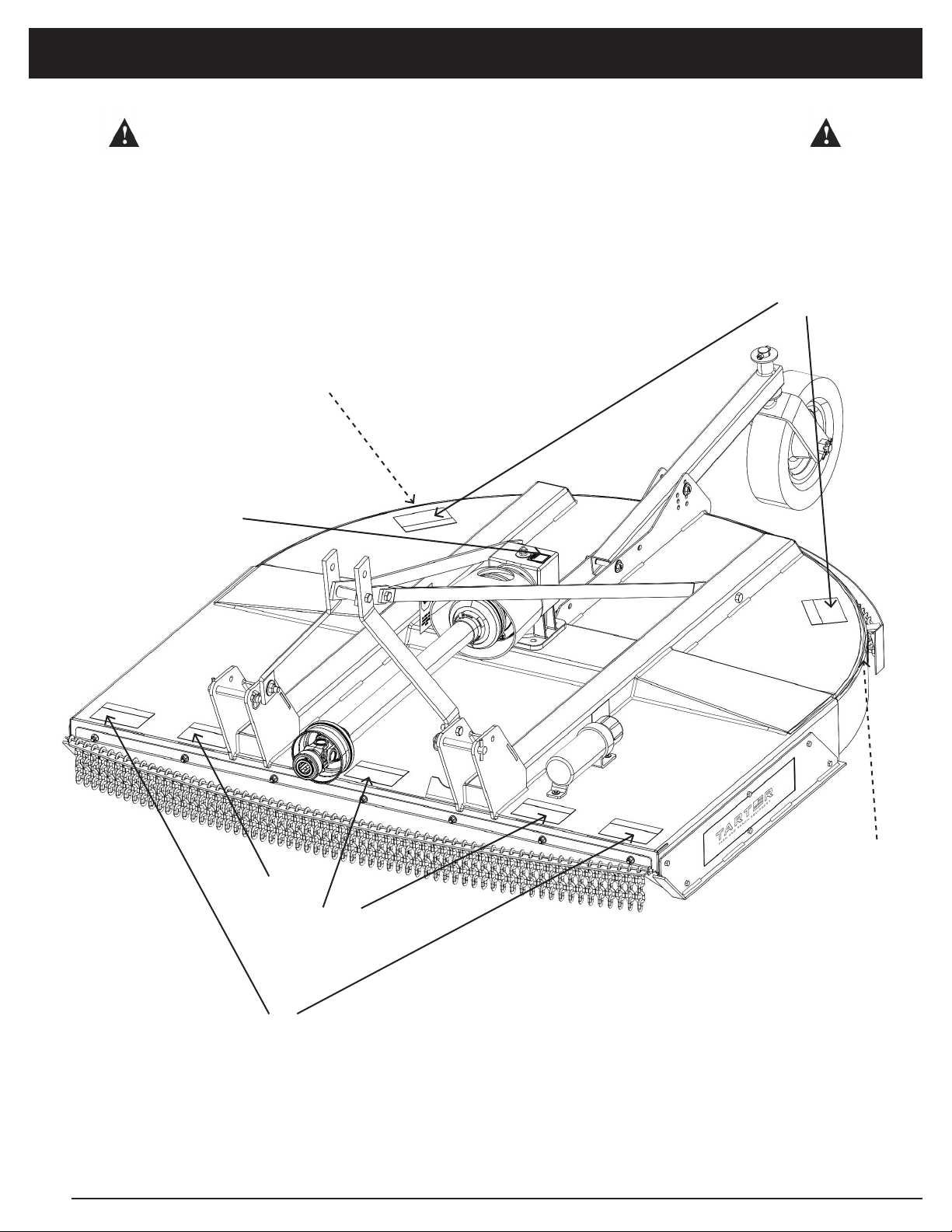
Major Components
NOTICE
All information, illustrations, and specifications in this manual are based on the latest information
available at the time of publication. Because we are always striving to improve our products, the
images could differ slightly from actual equipment. Specifications are subject to change without
notice. We also reserve the right to make changes at any time without notice.
Deck
A-Frame
Gearbox
PTO Shaft
Tail Wheel
Skid Shoes
Chain Guards
10
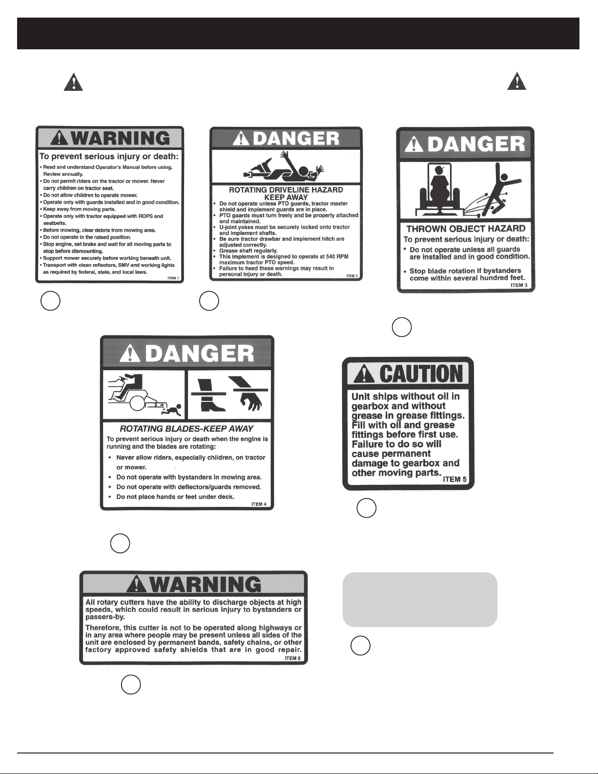
SAFETY and INSTRUCTIONAL DECALS
ATTENTION! BECOME ALERT! YOUR SAFETY IS INVOLVED!
Replace Immediately if Damaged!
SAFETY AND INSTRUCTION DECALS
1
3
7
6
5
2
4
7
11
SAFETY and INSTRUCTIONAL DECALS
ATTENTION! BECOME ALERT! YOUR SAFETY IS INVOLVED!
Replace Immediately if Damaged!
SAFETY AND INSTRUCTION DECALS
RED REFLECTOR
(2 Needed)
7RED REFLECTOR
Warning Label Sheet - Reorder Part #’s
Decals 1-6 (part # RC-DECALS) & Decal 7 (part # FT4003)
1SERIOUS INJURY 2ROTATING DRIVELINE
THROWN OBJECT
3
4ROTATING BLADES
5NEEDS OIL
6THROWN OBJECT
(2 needed)
(2 needed)
12
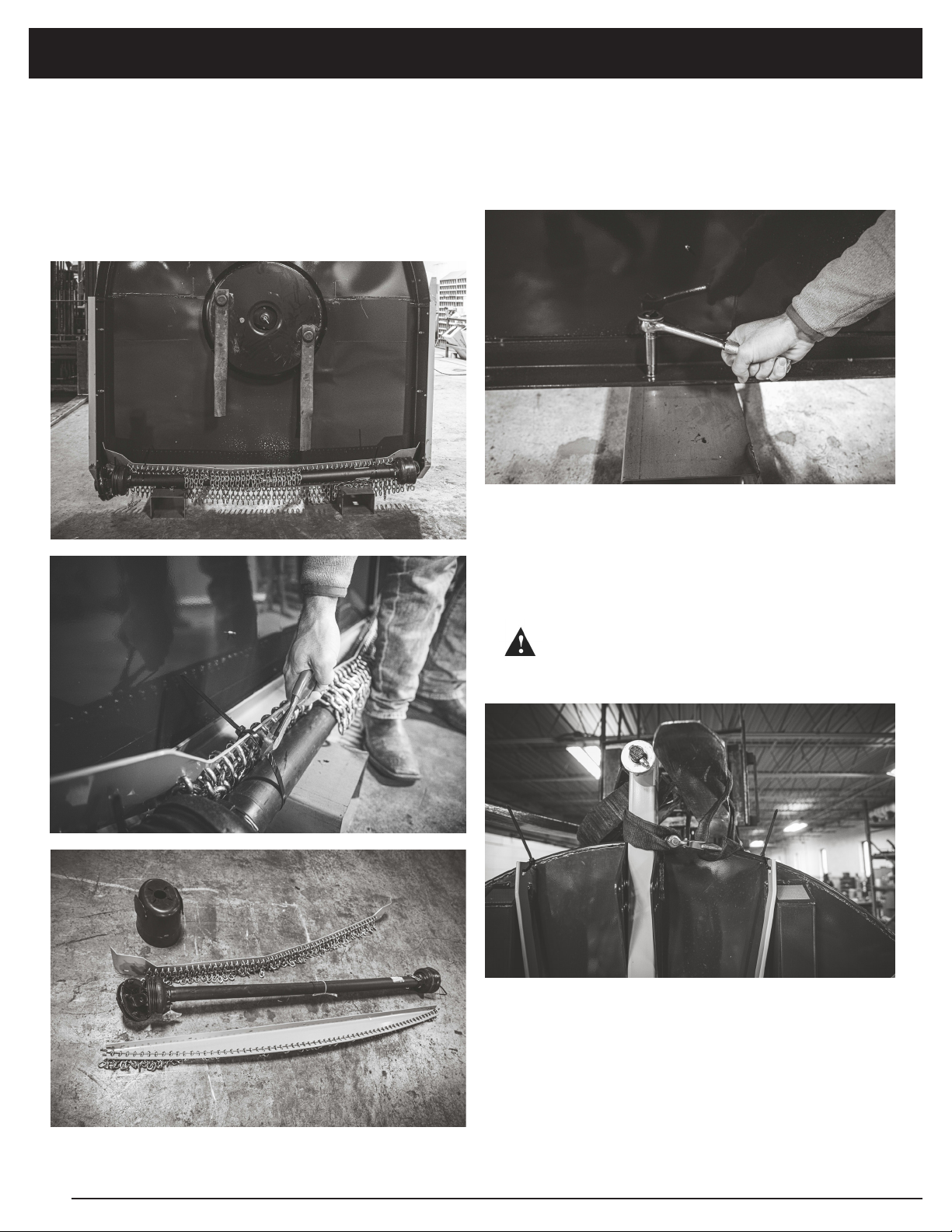
2. Remove hardware kits from manual holder
and set aside.
3. Remove bolts/nuts from shipping stands
using 9/16” socket.
4. Wrap lifting strap or chains around cutter
rear support frame and attach to hoist or
lifting device. Lower machine on to wooden
blocks.
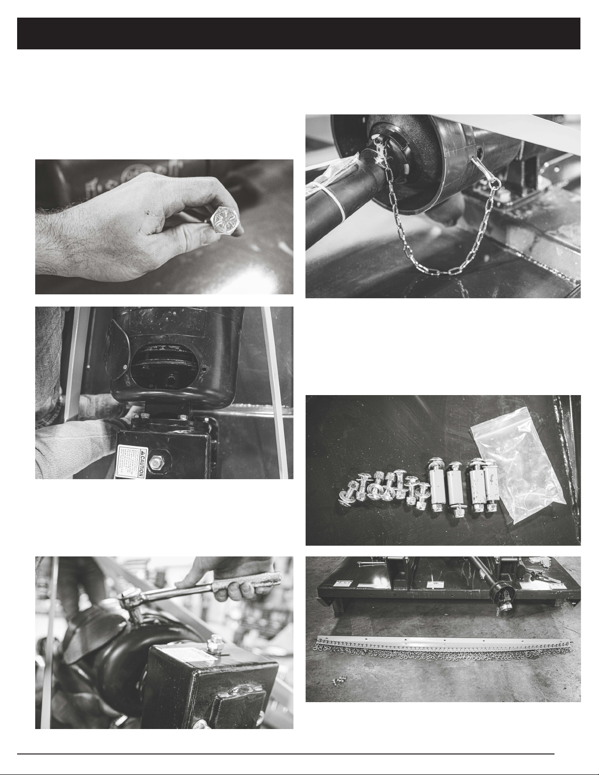
ASSEMBLY
CUTTER ASSEMBLY
1. From shipping position you will first
remove chain guards, PTO Shaft, and
Slip Clutch shield by cutting zip ties
underneath cutter. Set these 4 items aside.
Help prevent bodily injury ensure
cutter is stable in all directions and
blocks cannot tip over.
DANGER

13
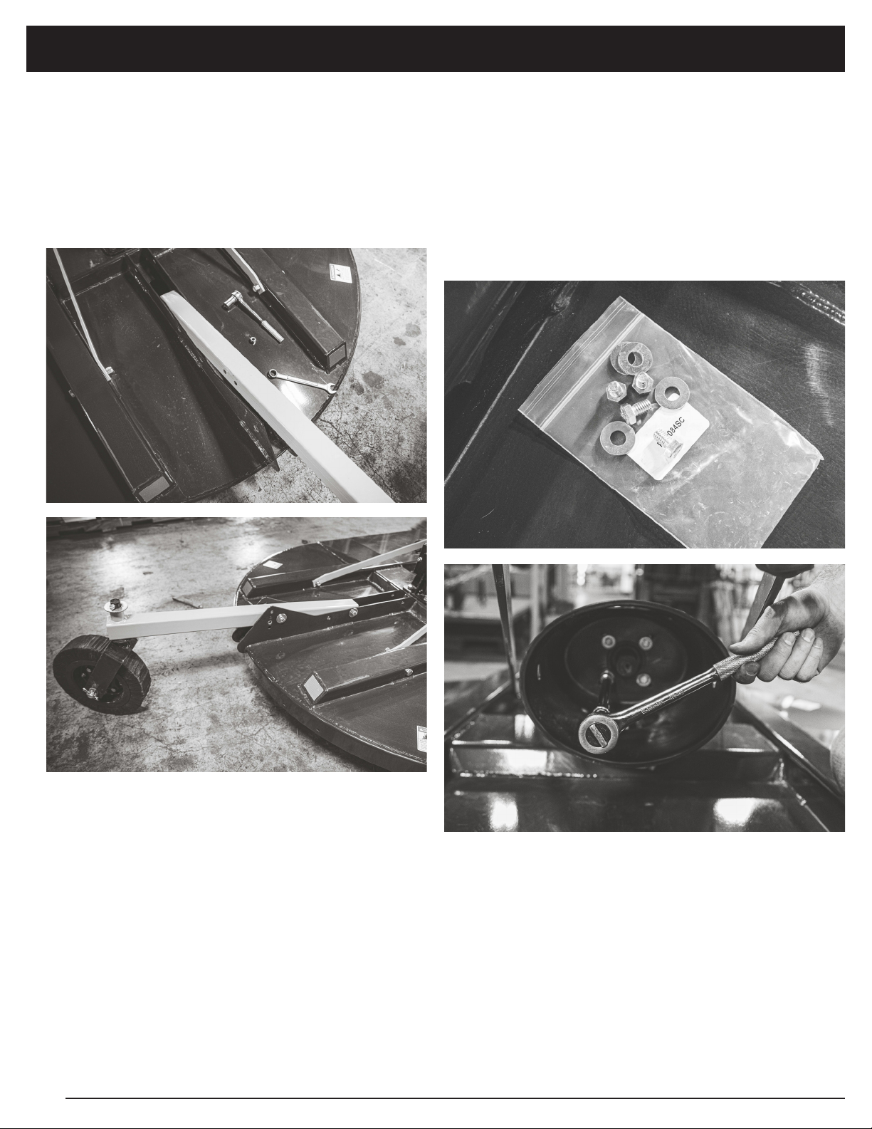
ASSEMBLY
5. Remove clip and hitch pin to allow
removal of shipping stands. Discard shipping
stands and replace hitch pins and clips.
6. Remove zip ties and protective cardboard
from hitch support straps.
7. Remove (2) bolts using 15/16” socket from
deck supports.
8. Move hitch to user position as shown and
attach hitch supports to the deck supports.
Replace the two bolts removed in Step 7.
(continued on next page)
14
ASSEMBLY
INSTALLING PTO SHAFT
1. Begin by removing the snap ring from the
gearbox input shaft.
2. Install slip clutch shield on gearbox using
the (4) supplied bolts and washers that were
previously removed from the manual holder
using a 1/2” socket and extension.
9. Move tailwheel assembly from the
shipping position to the user position by
removing the two retaining bolts, nuts, and
washers (using 3/4” wrench and socket.)
Slide tailwheel back and insert hardware in
slotted hole as shown. Insert hardware to
desired height setting in the rear.
15
ASSEMBLY
3. Push PTO driveline onto input shaft
towards gearbox aligning the holes for the
retaining bolt.
IMPORTANT: With slip clutch PTO only use 1/2”
Grade 8 retaining bolt indicated by 6 lines on
head of bolt as shown.
4. Utilizing the access hole in the slip clutch
guard insert the Grade 8 retaining bolt and
tighten using 3/4” wrench and socket with
extension.
ATTACHING CHAIN GUARDS
1. Using the remaining packaged hardware.
Lay front guard on ground with flange and
cable facing up as pictured.
5. Remove safety chain from bag on PTO Shaft
and attach the clip to the side of the slip clutch
shield as shown.
(continued on next page)
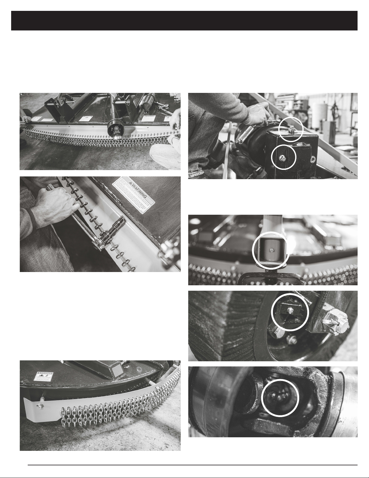
16
ASSEMBLY
INITIAL LUBRICATION
1. Before operating – fill gearbox with oil by
removing breather plug A and check plug
B, add EP80W-90 gear oil until level with
check plug hole. Reinstall both plugs.
2. Add grease to all grease fittings: (2)
tailwheel, (2) PTO Shaft cross bearings.
2. Lift guard straight up and attach (7) bolts,
nuts, and washers from the front of cutter
using 9/16” socket.
NOTE: Place carriage bolt inside of cutter
facing out.
3. To attach rear guard- use bolts with
spacers provided. Insert bolt from inside of
cutter, then slide spacer on. Attach nut from
outside of chain guard.
NOTE: It is important to install bolts sequentially
rather than starting with both ends. Hand
tighten until all hardware is in place.
AA
BB

17
Final Inspection and Adjustments
IMPORTANT: PTO driveline may be too long for some tractor models, causing tractor transaxle
damage. Modify driveline if necessary.
Attach rotary cutter to tractor and check cutter-to-tractor driveline telescoping length
clearance.
(See MAINTENANCE BEFORE EACH USE in Lubrication and Maintenance section.)
• Modify PTO Driveline (If Necessary)
1. To adjust the length, hold the half-shafts
next to each other in the shortest working
position and mark them.
2. Shorten inner and outer guard tubes
equally.
3. Shorten inner and outer sliding profiles by
the same length as the guard tubes.
4. Round off all sharp edges and remove burrs.
Grease sliding profiles. No other changes
may be made to PTO drive shaft and guard.
5. Chains must be fitted so as to allow
sufficient articulation of the shaft in all working
positions.
6. The PTO drive shaft must not be suspended
from the chains!
MODIFY PTO DRIVELINE
MODIFYING PTO
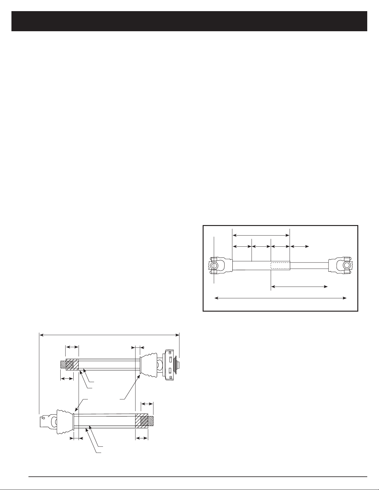
18
INNER SHAFT
INNER DRIVELINE
OUTER DRIVELINE
INNER SHIELD
OUTER SHAFT
OUTER SHIELD
UNIVERSAL
JOINT SHIELD
TRACTOR END
IMPLEMENT END
Figure 1 - Driveline Shortening
A
B
B
X
Y
X1
Y1
FREE LENGTH IMPLEMENT END
INNER PROFILEOUTER PROFILE
1/3 1/3 1/3 1/3 1/3
OVERLAP
MAXIMUM ALLOWABLE LENGTH
Outer Shielding has been removed for clarity.
FREE LENGTHTRACTOR END
Figure 2 - Driveline Maximum Extended Length
MODIFYING PTO
SIZING THE PTO SHAFT
Refer to Figure 1
1. Detach the driveline from tractor PTO shaft and
pull outer and inner drivelines apart.
2. Reattach outer driveline to tractor PTO shaft.
Pull on inner and outer drivelines to ensure
universal joints are properly secured.
3. Hold inner and outer drivelines parallel to each
other:
a. Measure 1” (“B” dimension) back from
outer driveline universal joint shield and
make a mark at this location on the inner
driveline shield.
b. Measure 1” (“B” dimension) back from
inner driveline universal joint shield and
make a mark at this location on the outer
driveline shield.
4. Remove driveline from tractor and gearbox
shafts.
5. Measure from end of inner shield to scribed
mark (“X” dimension). Cut off inner shield at the
mark. Cut same amount off the inner shaft (“X1”
dimension).
6. Measure from end of outer shield to scribed
mark (“Y” dimension). Cut off outer shield at the
mark. Cut same amount off the outer shaft (“Y1”
dimension).
7. Remove all burrs.
8. Continue with “Check Driveline Maximum
Length”.
CHECK DRIVELINE MAXIMUM
LENGTH
Refer to Figure 2
Make sure driveline’s collapsible length is
acceptable.
The driveline maximum allowable length must,
when fully extended, have a minimum overlap of
the profile tubes by not less than 1/3 the free length
with both inner and outer profile tubes being of
equal length.
1. Apply multi-purpose grease to the inside of the
outer shaft and reassemble the driveline.
2. Assemble the two driveline profiles together
with 1/3 of the profile tubes overlapping as
shown below. Once assembled, measure and
record the maximum allowable length for future
reference.
3. Attach inner driveline yoke to the cutter’s
gearbox shaft. Attach outer driveline yoke to the
tractor’s PTO shaft.
4. Move yoke ends of driveline back and forth to
insure they are secured to the tractor and cutter
shafts. Reattach any end that is loose.
IMPORTANT: Small chains are supplied with the
driveline. They must be attached to the inner
and outer driveline shields and to the cutter and
tractor to restrict shield rotation.
5. Hook driveline safety chain on the tractor end of
driveline to cutter frame. Re-latch safety chain
to the driveline shield.

19
DRIVELINE
LEVEL
Figure 3 - Check Driveline Maximum Angle
CHECK DRIVELINE MAXIMUM
ANGLE
Refer to Figure 3
IMPORTANT: To avoid premature driveline
breakdown, do not exceed an angle of 25° up or
down with the driveline while driveline is rotating.
If needed, set tractor 3-point left lever to limit
driveline angle at a maximum of 25° up.
1. Raise and lower implement to find maximum
driveline angle. Check to make certain the
driveline does not exceed 25° up or down.
2. If needed, set tractor 3-point lift height to keep
driveline from exceeding 25° up.
MODIFYING PTO
6. Hook driveline safety chain on the Rotary Cutter
end of driveline to the cutter frame. Re-latch
safety chain to driveline shield.
7. Start tractor and raise Rotary Cutter just enough
to remove support blocks.
8. Slowly engage tractor hydraulic 3-point control
lever to lower the cutter while checking for
sufficient drawbar clearance. Move drawbar in,
aside or remove if required.
9. Raise and lower implement to find maximum
extended driveline length. Check to make
certain the driveline does not exceed maximum
allowable length recorded in step 2.
10. If needed, set tractor 3-point lift height to stop
driveline from exceeding maximum allowable
length.
11. Continue with “Check Driveline Maximum Angle”
below.
20
OPERATION
a. Lower machine until rear wheel just touches
or is slightly above ground.
b. Engage tractor parking brake and/or place
transmission in PARK.
c. Disengage PTO.
d. Shut off tractor engine and remove key.
e. Wait until all moving parts have stopped.
f. Disconnect PTO driveline from tractor.
1. Loosen bolt and lock nut (B), remove bolt,
washers and lock nut (A), raise tail wheel to
highest position and install bolt, washer and
lock nut (A).
2. Using rockshaft control lever, position
front of cutter at desired cutting height at
location.
3. Adjust depth stop. (See your tractor
Operator’s Manual.)
4. Adjust center link so rear of cutter is
approximately
2 inches (51 mm) higher than front.
ADJUSTING CUTTING HEIGHT AND ANGLE
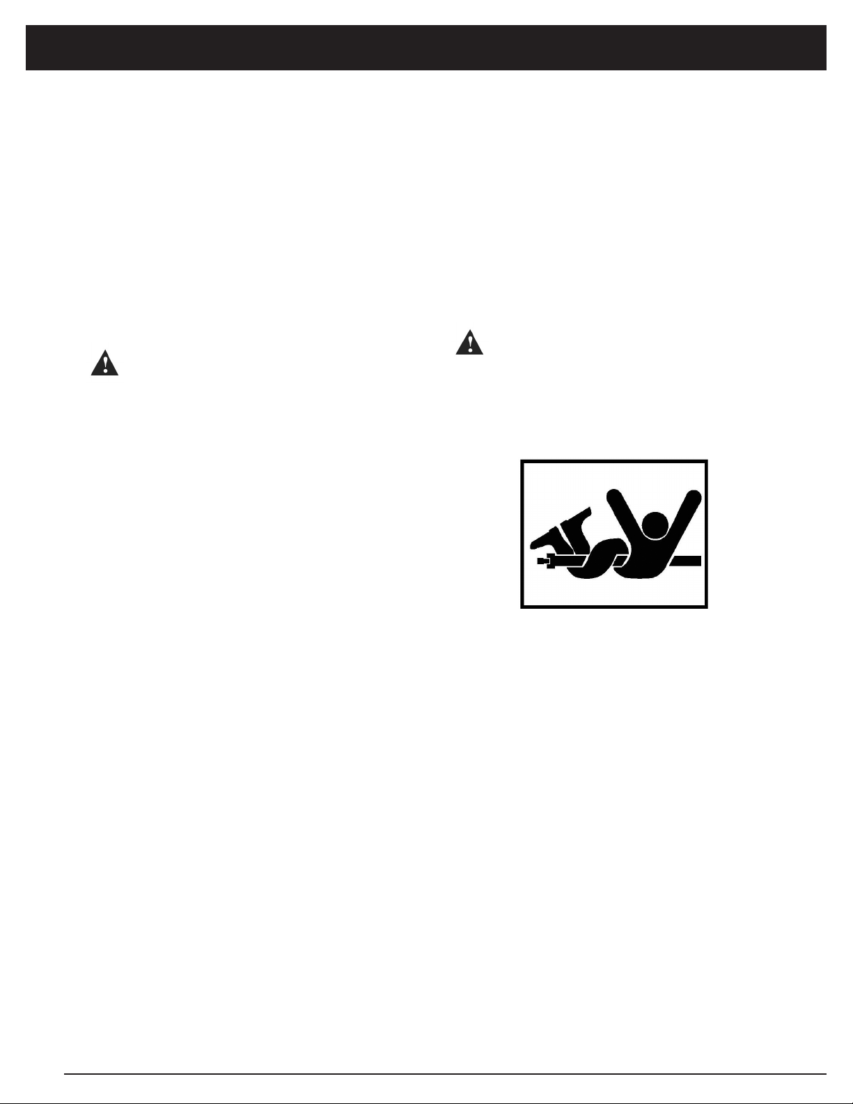
Help prevent bodily injury or death
caused by entanglement in
rotating driveline or blades.
Entanglement in rotating driveline
or being struck by blades can
cause serious injury or death.
Before making any adjustments:
DANGER
Only qualified people should operate this machine. Wear close fitting clothing and safe-
ty equipment appropriate to the job. It is recommended that tractor be equipped with
Rollover Protective Systems (ROPS) and that a seat belt be used. Before beginning op-
eration, clear work area of objects that may be picked up and thrown. Check for ditches,
stumps, holes or other obstacles that could upset tractor or damage rotary cutter. Al-
ways turn off tractor engine, set parking brake, and allow rotary cutter blades to come
to a complete stop before dismounting tractor.
PREPARING CUTTER FOR
OPERATION
IMPORTANT: To avoid damaging the machine
from impact on ground when lowering, adjust
rate at which hitch will lower.
1. Adjust tractor rockshaft rate-of-drop.
Allow at least two seconds for machine to
lower from full lift height to the ground.
(See your tractor Operator’s Manual.)
2. If equipped, disengage tractor hitch/
rockshaft control lever from transport lock
position and lower cutter to the ground.
(See your tractor Operator’s Manual.)
3. Adjust tractor lift links to level machine
side-to-side. (See your tractor Operator’s
Manual.)
4. Adjust cutting height and angle. (See
Adjusting Cutting Height and Angle in this
section.)
To help prevent severe injury or
death to you or someone else:
a. Do not engage tractor PTO
when cutter is in fully raised
position transport position).
b. Keep all persons away from
machine when raising and
lowering cutter.
DANGER
GENERAL SAFETY
Table of contents
Other Tarter Lawn And Garden Equipment manuals

Popular Lawn And Garden Equipment manuals by other brands


Essential Garden
Essential Garden WPI-012B owner's manual

Alpina
Alpina SF-5087 Instructions for use

Billy Goat
Billy Goat PL2500SPH owner's manual

Graf
Graf PLATIN Series Installation and maintenance instructions

Marsh
Marsh 241D installation guide

Pergola kits USA
Pergola kits USA CLASSIC CEDAR PERGOLA KIT Assembly manual


