Tascam X-17 User manual

Professional DJ Mixer
PUSH
OWNER’S MANUAL/ MODE D’EMPLOI / BEDIENUNGSANLEITUNG /
MANUALE D'ISTRUZIONI / Mezclador de DJ profesional
D00676200A
»
X-17

2 TASCAM X-17
English Important Safety Precautions
IMPORTANT (for U.K. Customers)
DO NOT cut off the mains plug from this
equipment. If the plug fitted is not suitable for the power
points in your home or the cable is too short to reach a power
point, then obtain an appropriate safety approved extension lead
or consult your dealer.
If nonetheless the mains plug is cut off, remove
the fuse and dispose of the plug immediately,
to avoid a possible shock hazard by inadvertent connection to
the mains supply.
If this product is not provided with a mains plug, or one has to
be fitted, then follow the instructions given below:
IMPORTANT. DO NOT make any connection to the larger
terminal which is marked with the letter E or by the safety earth
symbol ççor coloured GREEN or GREEN-and-YELLOW.
The wires in the mains lead on this product are coloured in
accordance with the following code:
BLUE : NEUTRAL
BROWN : LIVE
As these colours may not correspond with the coloured
markings identifying the terminals in your plug proceed as
follows:
The wire which is coloured BLUE must be connected to the
terminal which is marked with the letter N or coloured BLACK.
The wire which is coloured BROWN must be connected to the
terminal which is marked with the letter L or coloured RED.
When replacing the fuse only a correctly rated approved type
should be used and be sure to re-fit the fuse cover.
IF IN DOUBT — CONSULT A COMPETENT
ELECTRICIAN.
TO THE USER
This equipment has been tested and found to
comply with the limits for a Class A digital device,
pursuant to Part 15 of the FCC Rules. These limits
are designed to provide reasonable protection
against harmful interference when the equipment
is operated in a commercial environment. This
equipment generates, uses, and can radiate radio
frequency energy and, if not installed and used in
accordance with the instruction manual, may
cause harmful interference to radio
communications.
Operation of this equipment in a residental area is
likely to cause harmful interference in which case
the user will be required to correct the
interference at his own expense.
CAUTION
Changes or modifications to this equipment not
expressly approved by TEAC CORPORATION for
compliance could void the user's authority to
operate this equipment.
For U.S.A
TASCAM X-17 51
Block diagram / Schéma synoptique / Blockschaltbild / Schema a blocchi / Diagrama de bloques
Block diagram / Schéma synoptique / Blockschaltbild /
Schema a blocchi / Diagrama de bloques
Sheet 2 of 26
Forthe consumers inEurope
WARNING
This is a Class A product. In a domestic environment, this
product may cause radio interference in which case the user
may be required to take adequate measures.
Pour les utilisateurs en Europe
AVERTISSEMENT
Il s’agit d’un produit de Classe A. Dans un environnement
domestique, cet appareil peut provoquer des interférences
radio, dans ce cas l’utilisateur peut être amenéàprendre
des mesures appropriées.
Für Kunden in Europa
Warnung
Dies is eine Einrichtung, welche die Funk-Entstörung nach
Klasse A besitzt. Diese Einrichtung kann im Wohnbereich
Funkstörungen versursachen ; in diesem Fall kann vom
Betrieber verlang werden, angemessene Maßnahmen
durchzuführen und dafür aufzukommen.

TASCAM X-17 3
IMPORTANT SAFETY INSTRUCTIONS English
1) Read these instructions.
2) Keep these instructions.
3) Heed all warnings.
4) Follow all instructions.
5) Do not use this apparatus near water.
6) Clean only with dry cloth.
7) Do not block any ventilation openings. Install in accordance
with the manufacturer's instructions.
8) Do not install near any heat sources such as radiators, heat
registers, stoves, or other apparatus (including amplifiers) that
produce heat.
9) Do not defeat the safety purpose of the polarized or
grounding-type plug. A polarized plug has two blades with one
wider than the other. A grounding type plug has two blades and
a third grounding prong. The wide blade or the third prong are
provided for your safety. If the provided plug does not fit into
your outlet, consult an electrician for replacement of the obsolete
outlet.
10)Protect the power cord from being walked on or pinched
particularly at plugs, convenience receptacles, and the point
where they exit from the apparatus.
11)Only use attachments/accessories specified by the
manufacturer.
12)Use only with the cart, stand, tripod, bracket, or table
specified by the manufacturer, or sold with the apparatus. When
a cart is used, use caution when moving the cart/apparatus
combination to avoid injury from tip-over.
13) Unplug this apparatus during lightning storms or when
unused for long periods of time.
14) Refer all servicing to qualified service personnel. Servicing is
required when the apparatus has been damaged in any way,
such as power-supply cord or plug is damaged, liquid has been
spilled or objects have fallen into the apparatus, the apparatus
has been exposed to rain or moisture, does not operate
normally, or has been dropped.
•Do not expose this apparatus to drips or splashes.
•Do not place any objects filled with liquids, such as vases, on
the apparatus.
•Do not install this apparatus in a confined space such as a
book case or similar unit.
•The apparatus draws nominal non-operating power from the
AC outlet with its POWER switch in the off position.

4 TASCAM X-17
English Introduction
Table of contents
Introduction ................................................................... 4
Some notes and precautions.................................... 4
Serial number, etc.................................................... 4
Rack-mounting the unit........................................... 4
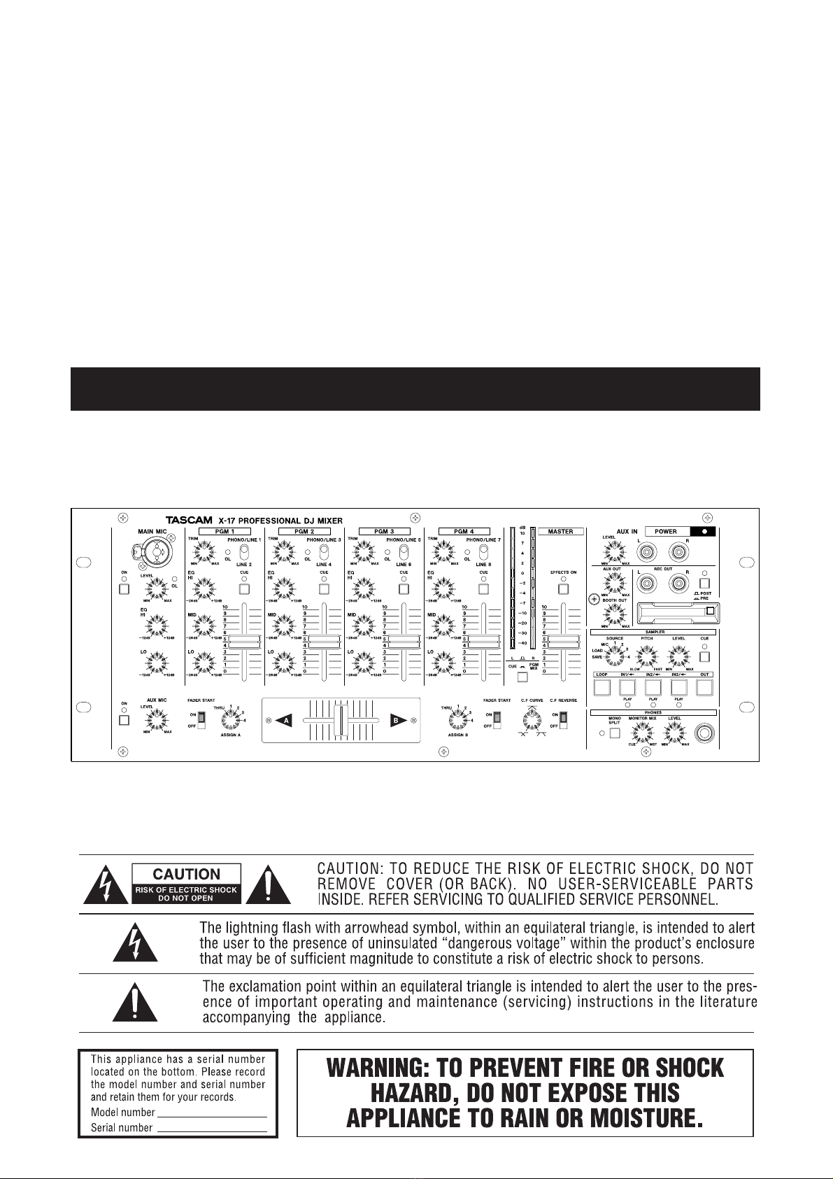
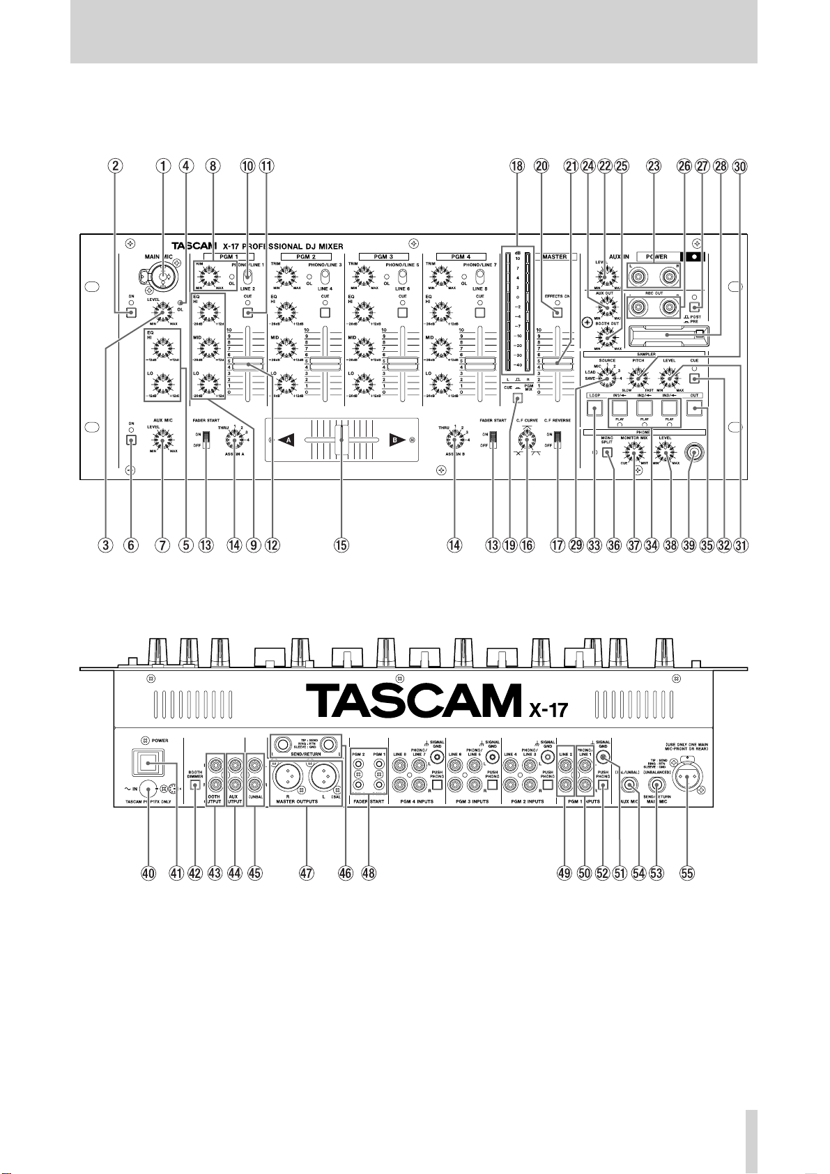
Features and controls..................................................... 5
Top panel................................................................. 6
How to replace the fader ......................................... 8
Rear panel................................................................ 8
Sampler ................................................................... 9
Specifications............................................................... 11
Block diagram.............................................................. 51
Introduction
The X-17 is a sophisticated 4–PGM DJ mixer which
allows you to connect many devices, and mix in a
creative way. With a sophisticated layout, the X-17
combines easy operation with a wide range of functions.
It is VERY IMPORTANT that you read this manual
before connecting and using the mixer, in order get the
best out of it.
We recommend contacting our authorized Technical
Service department, or that of your TASCAM dealer or
distributor if any maintenance or repair work is
necessary, so that you can continue to enjoy the best
possible performance and operation.
Some notes and precautions
Treat the X-17 as you would any other piece of precision
equipment.
Avoid exposing it to extremes of temperature and
humidity and avoid mechanical shocks and vibration.
Keep the unit away from strong magnetic fields (TV sets,
computer monitors, large electric motors, etc.).
Environmental considerations
The X-17 may be used in most areas, but to maintain top
performance, and prolong operating life, observe the
following environmental conditions:
The nominal temperature should be between 5°C and
35°C (41°F and 95°F).
Relative humidity should be 30 to 90 degrees non-
condensing.
As the unit may become hot during operation, always
leave sufficient space above and around the unit for
ventilation.
Do not install this equipment in a confined space such as
a bookcase or similar unit.You should not place the unit
on a piece of equipment generating heat, an amplifier for
example, to avoid possible problems with overheating.
Only use the AC adaptor provided with the X-17, and do
not use the adaptor with any other equipment. Always
make sure that the voltage supplied to the adaptor
matches the input voltage as specified on the adaptor. In
case of doubt, consult a qualified electrician.
To avoid hum in the audio, make sure that the power
cable is far away from the signal cables.
When transporting the unit, always use the original
packing materials or a properly-designed equipment
case. For this reason, we strongly recommend that
you save all the packing materials that came with
the X-17, in case you need to transport it in the
future.
Connections to other equipment
It is extremely important that the power is turned off on
all units when making or breaking connections to or from
the X-17.
When turning power on, it is usually a good idea to start
with the source (turntables, CD players, etc.), then the X-
17 and finish with the amplifier system.
Turning power off should be done in the other direction
(amplifiers first, then other equipment).
If you have to turn off the X-17 and turn it on again,
always wait for 3 or more seconds between turning the
unit off and on again.
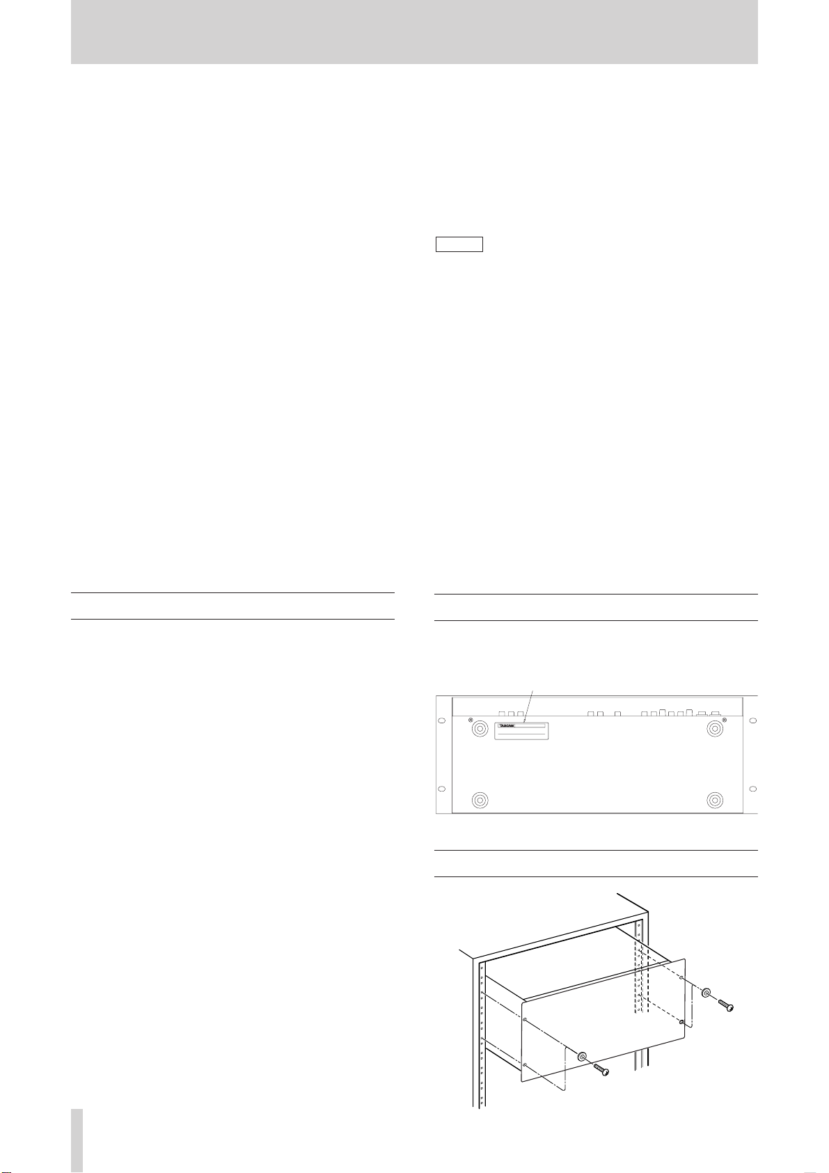
Serial number, etc.
The serial number of the X-17 is located on a sticker at
the rear of the unit on the bottom panel. Make a note of
this for future reference (warranty, etc.).
NOTE
Rack-mounting the unit

TASCAM X-17 5
Features and controls English
Features and controls
PUSH

6 TASCAM X-17
English Features and controls
Top Panel
1MAIN MIC input
Connect the main microphone to this XLR/TRS
connector that can accept both balanced and unbalanced
signals.
This is a “combo” type jack which accepts both XLR
type and 1/4” TRS type connectors.
Connections are as follows:
XLR TRS
GND: Pin 1 Sleeve
HOT: Pin 2 Tip
COLD: Pin 3 Ring
There is another MAIN MIC input connector on the
rear panel. Only use either the connector on the
rear panel or the top panel (you cannot use both at
the same time).
The MAIN MIC channel also has a dedicated insert jack
on the rear panel.
2ON switch and indicator for MAIN MIC
channel
Push for on, and push again for off. When this switch is
on, the MAIN MIC channel is active and the indicator
lights.
3MAIN MIC LEVEL
Adjusts the signal level of both the top and rear MAIN
MIC inputs.
4OL indicator
When the MAIN MIC and/or AUX MIC input signal
cause an overload, this indicator lights (post-insert, but
pre-EQ).
All input adjustments must be done very carefully.
Use the level meters and/or headphones for
reference. Make sure that the top red meter LEDs
do not all light up, as this shows that the signal can
clip (overload and distort).
5MIC EQ
2-band EQ (HI and LO, both cutting and boosting by 12
dB) affecting both the the MAIN MIC and AUX MIC
input signals.
6ON switch and indicator for AUX MIC channel
Push for on, and push again for off. When this switch is
on, the AUX MIC (auxiliary microphone) channel is
active and the indicator lights.
NOTE
NOTE
7AUX MIC LEVEL
Adjusts the signal level of the AUX MIC input.
8TRIM controls and OL indicators
Adjust the input signal level for each PGM.
If a PGM’s input signal causes an overload, the PGM’s
OL indicator lights.
All input sensitivity adjustments must be done very
carefully. Use the level meter and/or headphones
for reference. Make sure that the top red meter
LEDs do not all light up, as this shows that the
signal can clip (overload and distort).
9PGM EQ
Provides three-band EQ (equalization) for each PGM
signal. The control for each band can cut the band by up
to 26 dB and boost it by up to 12 dB.
If all EQ controls on a PGM are set to –26dB, this will
almost completely cut the signal of the PGM.
0Input Selector switches
Select the input signal for each PGM. Each PGM can
select from either a LINE input or a PHONO/LINE input
(the selection between phono and line is made on the rear
panel).
qCUE switches and indicators
Sends the pre-fader signals of the PGMs to the CUE
monitor bus. When CUE is activated for a PGM, the
CUE indicator lights.
wPGM faders
Adjust the level of the PGMs
eFADER START switches
Set the automatic start of A and B using the cross-fader
on or off.
rCross-fader ASSIGN selectors
Select the signal sources assigned to the A and B cross-
fader outputs. Each of the four PGMs can be selected as a
signal source, and there is also a THRU setting, which
means that no PGM is assigned to the cross-fader on that
side. Use the PGM and MASTER faders to adjust the
output if this setting is made.
tCross-fader
Mixes between the A and B outs, assigned from the PGM
signals.
The cross-fader can be reversed, and you can set the
cross-fader curve to match your preferences (see below).
It is possible for you to replace the cross-fader if this
becomes necessary (see below for details).
NOTE

TASCAM X-17 7
Features and controls English
yC.F CURVE
Allows you to adjust the cross-fader response curve from
soft (counter-clockwise) to hard (clockwise).
uC.F REVERSE
Sets the direction of the cross-fader.
When in the OFF, position, moving the cross-fader
toward A increases the volume of the A signal and
moving the cross-fader toward B increases the volume of
the B signal. The ON setting reverses this
iMeters
This pair of peak meters indicates either the post-fader
(PGM or MASTER) MASTER signal level in stereo, or
the mono CUE signal levels.
oMeter selection switch (L/R –CUE/PROG)
Switches the meter indication between the MASTER
program (the switch is up) and the CUE signals (the
switch is depressed).
pEFFECTS ON switch and indicator
When this switch is on, the indicator lights, and the
master external effect loop is active.
aMASTER fader
Adjusts the level of the signal from the MASTER
OUTPUT jacks (both the balanced XLR and the
unbalanced RCA connectors).
sAUX IN LEVEL
Adjusts the level of the signals from the AUX IN jacks.
dAUX IN
Use these unbalanced RCA connectors to connect line
level equipment, such as CD players, cassette decks,
DAT decks, MD players, or another X-17, etc. This input
signal is input immediately pre-MASTER fader.
fAUX OUT LEVEL
Adjusts the signal level output from the AUX OUTPUT
jacks.
gBOOTH OUT LEVEL
Adjusts the signal level output from the BOOTH
OUTPUT jacks.
hREC OUTPUT
These unbalanced RCA jacks output the pre-MASTER
fader signal. This can be useful for a number of purposes:
for example, you could connect a recorder to these jacks,
and record your live performance without the MASTER
level affecting the recording.
jPRE/POST insert switch for REC OUT
This switch controls what is output from the REC OUT
jacks. When this switch is in the PRE setting (the switch
is depressed):
The four PGM signals and the sampler signal,
without the master insert loop.
In the POST setting:
The four PGM signals and the sampler signal,
with the master insert loop, the AUX IN signal,
and both the MAIN and AUX MIC signals.
kCompactFlashTM card slot
This slot holds a CompactFlash card which you can use
to save sampled sounds from the X-17’s internal memory,
and to load them into the X-17’s internal memory. This
allows you to carry your favorite samples in a compact,
robust format.
The card can only be inserted in one direction. Press the
eject button to the right of the slot to eject the card.
Cover this slot using the attached protective cover when it
is not in use.
See the section on the sampler below for full details of
how to use the card and the sampler.
CompactFlash is a trademark of the CompactFlash
Association.
lSAMPLER SOURCE selector
SAVE: Saves the X-17’s internal sample data to the
CompactFlash card.
LOAD: Loads sample data from the CompactFlash card
into the X-17’s internal memory.
MIC, 1-4: Select the sampling source (the MIC inputs or
any of the 4 PGMs).
;SAMPLER PITCH
Adjusts the sampler’s playback pitch and speed from half
speed (SLOW) to double speed (FAST).
zSAMPLER LEVEL
Adjusts the output level of the sampler signal.
xSAMPLER CUE switch and indicator
Sends the sampler pre-LEVEL signal to the CUE monitor
(the indicator lights when this is activate).
cSAMPLER LOOP key and indicator
Toggles sampler loop play on and off (the indicator lights
when sampler loop play is active).
vIN/<- keys (IN1, IN2, IN3)
Start sample recording or playback. When the SAMPLER
SOURCE selector is set to LOAD, these keys load
sample data from the CompactFlash card.

8 TASCAM X-17
English Features and controls
bOUT key
Stops sample recording or playback. When the
SAMPLER SOURCE selector is set to SAVE, this key
saves the X-17’s internal sample data to the
CompactFlash card.
nMONO SPLIT switch and indicator
Selects headphone monitoring mode: either MONO
SPLIT mode (the indicator is lit) or STEREO mode (the
indicator is unlit).
STEREO mode: You monitor the CUE signal and
MASTER signal as determined by the PAN
control.
MONO SPLIT: You monitor the CUE signals in
mono from the left headphone, and the
MASTER signal in mono from the right
headphone.
mMonitor MIX
Adjusts the balance in the headphones between the CUE
signal and the MASTER signal.
,PHONES LEVEL
Adjusts level of the signals output through the
headphones.
.PHONES
Connect a standard pair of stereo headphones to this 1/4”
jack.
How to replace the cross-fader
1. Move the fader to the top and remove the fader knob.
2. Remove the two screws retaining the fader.
3. Remove the fader.
4. Unplug the multiway connector connecting the X-17
to the fader.
5. Replace the fader with a new one, and connect the
multiway connector to the new fader.
6. Secure the new fader with the screws removed in the
first step.
Rear Panel
/AC Adaptor in
Use this jack to connect the PS-P17X AC adapter which
comes with your X-17.
Insert the plug following the arrow position of the AC
adapter plug, and the white dot on the rear panel.
DO NOT use any adapter with the X-17 except the
PS-P17X adapter supplied with the X-17.
Connect the AC adapter jack to the X-17 in the way
shown on the illustration on the rear panel of the
X-17. If you connect the AC adapter in any other
way, you may damage the X-17.
!POWER switch
@BOOTH DIMMER switch
When this switch is on, and when the MAIN MIC ON
switch is pressed, the level of the signal from the BOOTH
OUTPUT jacks is reduced by 20dB.
#BOOTH OUTPUT
These unbalanced RCA connectors output the pre-
MASTER fader signal, whose level is adjusted using the
BOOTH OUT control.
Use the BOOTH DIMMER switch to reduce the level of
this signal.
$AUX OUTPUT
These unbalanced RCA connectors output the pre-
MASTER fader signal, whose level is adjusted using the
AUX OUT control.
%MASTER OUTPUT (UNBAL)
These unbalanced RCA connectors output the master
output signals (post-MASTER fader).
^SEND/RETURN
Use these 1/4” TRS connectors (unbalanced) to insert an
external effect in the MASTER OUTPUT signal path.
This includes the four PGMs and the sampler.
The connector is wired as follows.
GND: Sleeve
SEND: Tip
RETURN: Ring
&MASTER OUTPUT (BAL)
These balanced XLR connectors output the master output
signals (post-MASTER fader), wired as follows:
GND: Pin 1
HOT: Pin 2
COLD: Pin 3
WARNING

TASCAM X-17 9
Features and controls English
*FADER START connectors
Connect devices supporting the fader start operation to
these mini-jacks.
You can enable the cross-fader start function
independently for the A and B outputs.
Move the cross-fader to start and/or stop (back cue) the
PGM A or B source automatically.
The fader start signal is output from the tip, and the
fader stop (back cue) signal is output from the
sleeve. The ground for these connections is
provided by the signal ground of the device to
which the fader start is made.
(LINE inputs
Use these unbalanced RCA jacks to connect line level
equipment, such as CD players, cassette decks, MD
decks, etc.
)PHONO/LINE inputs
When the appropriate PUSH PHONO switch is in the
PHONO position (pushed in), connect turntables
equipped with MM (moving magnet) cartridges to these
unbalanced RCA jacks. When the switch is in the LINE
position (out) connect line level equipment, such as CD
players, cassette decks, MD decks, etc.
Always use the supplied shorting RCA plugs in any
PHONO jacks where a turntable is not connected.
When the PUSH PHONO switch is set to PHONO,
only connect turntables equipped with an MM
cartridge to these connectors. Do not connect such
turntables to any other connectors.
QSIGNAL GND terminals
If the turntables you use are fitted with grounding wires,
connect them to these GND terminals to reduce noise and
hum.
WPUSH PHONO switches
Push this switch in to use the odd-numbered (1, 3, 5 and
7) LINE/PHONO inputs with turntables. Leave it out to
use these inputs with other equipment (CD players, MD
decks, etc.).
Turn the power OFF on all amplifier systems, etc.
when using these switches. When these switches
are pressed, loud noises are produced that may
damage hearing and equipment.
WARNING
WARNING
NOTE
EMAIN MIC SEND/RETURN
Use this TRS 1/4” jack (unbalanced) to inserts an external
effect in the MAIN MIC signal path.
The connections are follows:
GND: Sleeve
SEND: Tip
RETURN: Ring
RAUX MIC input
Connect an auxiliary microphone to this balanced TRS
connector, wired as follows:
GND: Sleeve
HOT: Tip
COLD: Ring
TMAIN MIC input
Connect the microphone to this balanced XLR connector,
wired as follows:
GND: Pin 1
HOT: Pin 2
COLD: Pin 3
There is another MAIN MIC input connector on the
top panel. Only use either the connector on the rear
panel or the top panel (you cannot use both at the
same time).
Sampler
The X-17 includes three samplers, each of which can
record 30 seconds of sample data at 16-bit resolution.
These samples can be stored on and loaded from a CF
card (card formats other than CompactFlash do not work
with the X-17) of at least 16MB capacity.
The X-17 uses TASCAM’s own sample data format.
You can only use an X-17 to load and save sample
data.
Sampling
You can record samples from PGMs 1 through 4 or from
the MIC signals. When making a sample, the sampling
point is at the pre-fader point of PGMs 1 through 4.
1. Use the SAMPLER SOURCE selector to select the
sampling source (PGM 1-4 or MIC).
2. To start sampling, press an unlit IN key (IN1, IN2 or
IN3). The unlit key shows that the sampler is empty.
Sampling starts, the IN key lights, and the OUT key
starts to flash.
NOTE
NOTE

10 TASCAM X-17
English Features and controls
3. Stop recording by pressing the OUT key. If the
maximum recording time (30 seconds) is reached.
recording will stop automatically. The IN key you
pressed earlier, and the OUT key both light.
Erasing sample data
When a sampler contains data (its IN key is lit), press and
hold the OUT key and press the IN key to erase the
sample data. The IN key goes out. If no samplers contain
data, the OUT key goes out as well.
Playback
1. When a sampler contains data (its IN key is lit) press
its IN key to start playback. The appropriate PLAY
indicator lights and playback starts from the
beginning of the sample. Pressing any IN key again
during playback will start playback from the start of
the appropriate sample (including the currently-
playing one).
Note that the X-17 can hold three samples but only
one can be played at a time.
2. Use the LEVEL knob to adjust the output level.
3. Stop playback by pressing the OUT. The appropriate
PLAY indicator goes out.
Looped Playback
1. Press LOOP key to light it. When it is lit, pressing one
of the IN keys starts looped playback, and the
appropriate PLAY indicator lights.
2. When the LOOP key is lit, and looped playback is
going on, you can press LOOP to turn off the key and
stop the looping. This does not stop the playback,
though. Playback stops at the end of the sample (or
when you press the OUT key).
Sampler pitch and tempo control
1. Use the PITCH control to adjust the playback pitch
and speed. The pitch range is from half speed
(SLOW) to double speed (FAST).
Saving samples to a CompactFlash card
Note that when you turn off the X-17, all sample data not
saved on cards is lost. Save samples to a CompactFlash
card using the procedure described here.
1. Insert the Compact Flash card into the slot.
Note that this operation erases all data on the card.
If there is any data you want to keep on a card, you
should not save to that card.
NOTE
NOTE
2. Set the SAMPLER SOURCE selector to the SAVE
position. The OUT key starts to flash.
3. Press the OUT key. It lights and the save operation
starts. If any data is already stored on the card, it is
deleted, and the save starts. As data is saved from
each sample, the IN key for that sample flashes.
4. After the last sample has been saved, the OUT key
flashes, and the IN keys return to the state they were
in before the save operation (lit keys indicate a sample
is present).
Loading samples from a CompactFlash card
Note that this operation erases all samples currently
in the X-17’s memory. If there are any samples in
memory that you want to keep, you should save
them to another card first.
1. Insert the CompactFlash card into the slot.
2. Set the SAMPLER SOURCE SELECTOR to the
LOAD position. The IN1/<- key starts to flash.
3. Press the IN1/<- key. It flashes, and the load operation
starts.
4. After the load operation has finished and samples
have been loaded, the IN keys light (if one sample has
been loaded, IN1 lights, if two samples have been
loaded, IN1 and IN2 light, if three samples have been
loaded, all keys light. If there were no samples to be
loaded on the card, no keys are lit.
5. After the load operation is finished, the IN keys
corresponding to the loaded samples will light. If no
samples have been loaded from the card, no keys will
be lit.
NOTE

TASCAM X-17 11
Specifications English
Specifications
LINE IN (PGM1-4):
RCA, unbalanced
Input level: –10 dBV
Input impedance: 10 kΩ
PHONO/LINE inputs (PGM1-4)
RCA, unbalanced
PHONO position
Input level: –54 dBV
Input impedance: 47 kΩ
RIAA equalization
LINE position
Input level: –10 dBV
Input impedance: 10 kΩ
MAIN MIC input (on the top panel)
XLR/TRS, balanced/unbalanced
Input level: –50 dBV
Input impedance: 2.8 kΩ
MAIN MIC input (on the rear panel)
XLR, balanced
Input level: –50 dBV
Input impedance: 2.8 kΩ
AUX MIC input (on the rear panel)
TRS, balanced/unbalanced
Input level: –50 dBV
Input impedance: 2.8 kΩ
AUX IN (on the top panel)
RCA, unbalanced
Input level: –10 dBV
Input impedance: 10 kΩ
MASTER OUTPUTS (BAL)
XLR, balanced
Nominal output level: +4 dBu
Output impedance: 75 Ω
MASTER OUTPUTS (UNBAL)
RCA, unbalanced
Nominal output level: 0 dBV
Output impedance: 100 Ω
BOOTH OUTPUT:
RCA, unbalanced
Nominal output level: 0 dBV
Output impedance: 100 Ω
REC OUTPUT:
RCA, unbalanced
Nominal output level: –10 dBV
Output impedance: 100 Ω
AUX OUTPUT:
RCA, unbalanced
Nominal output level: 0 dBV
Output impedance: 100 Ω
SEND/RETURN
TRS, unbalanced
Nominal output level(send): –4 dBV
Output impedance: 100 Ω
Input level(return): –4 dBV
Input impedance: 10 kΩ
MAIN MIC SEND/RETURN
TRS, unbalanced
Nominal output level(send): –4 dBV
Output impedance: 100 Ω
Input level(return): –4 dBV
Input impedance: 10 kΩ
PHONES:
100 mW + 100 mW, (at 33 Ω)
Audio Performance
Frequency response:
LINE IN: 20 Hz to 20 kHz, +/–1.0 dB
PHONO IN: 30 Hz to 15 kHz, +/–2.0 dB
(RIAA)
MIC IN: 30 Hz to 18 kHz, +/–3.0 dB
Signal to nose ratio:
LINE IN: 78 dB (IHF A Weighting)
PHONO IN: 70 dB (IHF A Weighting)
MIC IN: 60 dB (IHF A Weighting)
Total harmonic distortion:
LINE IN: <0.1 %
PHONO IN: <0.2 %
MIC IN: <0.2 %
Crosstalk >60 dB (@1 kHz)
PGM EQ
HI: +12 dB to –26 dB
MID: +12 dB to –26 dB
LO: +12 dB to –26 dB
Filter (cut frequency at –6dB, slope 12dB/oct)
HI: 6.5 kHz
MID: 6.5 kHz & 200 Hz
LO: 200 Hz
MIC EQ
HI: 5.5 kHz, +12 dB to –12 dB
LO: 125 Hz, +12 dB to –12 dB
Power requirement: 120 V (60 Hz)
230 V (50Hz)
Power consumption: 27 W
Dimension (w x h x d): 482 x 176 x 102 (mm)
19 x 6.9 x 4 (in)
Weight: 4.3 kg, 9.48 lbs (main unit)
0.8 kg, 1.8 lbs (PS-P17X AC
adaptor)
Applicable electromagnetic environment:
E4
Peak inrush current: 1.6 A
Supplied accessories
Shorting RCA plug for PHONO x 8
AC Adaptor (PS-P17X) x 1
Operation manual x 1
All specifications subject to change without notice.
(1) (3.4)
(58)43.6
(20)1025
176
102 (37)(37)
435
482
465
(28.6)
(20)
143

12 TASCAM X-17
Français Consignes de sécurité importantes
IMPORTANT (pour le Royaume-Uni)
Ne modifiez pas le cordon d’alimentation de cet
appareil. Si la fiche qui le termine ne correspond pas aux
prises murales de votre domicile, ou si le câble est trop court
pour atteindre une de ces prises, procurez-vous une rallonge du
modèle approprié, conforme aux normes de sécurité, ou
consultez votre revendeur.
Si le cordon secteur vient à être coupé ou endommagé, retirez le
fusible de l’appareil puis débranchez immédiatement la prise,
afin d’éviter tout court-circuit ou électrocution suite à une mise
sous tension par inadvertance.
Si ce produit a été livré sans cordon secteur, ou avec un modèle
inapproprié,lisez les instructions ci-après et suivez-les
scrupuleusement :
IMPORTANT. N’EFFECTUEZ AUCUNE connexion au
niveau de la broche repérée par la lettre E ou par le symbole de
masse çou portant un fil de couleur VERTE ou VERT et
JAUNE.
Les couleurs du cordon secteur livré avec cet appareil respectent
le code suivant:
BLEU : NEUTRE
MARRON : PHASE
Comme ces couleurs ne correspondent pas forcément à celles
idientifiant les broches de votre prise secteur, procédez comme
suit :
Le fil BLEU doit être relié à la broche repérée par la lettre N ou
coloriée en NOIR.
Le fil MARRON doit être relié à la broche repérée par la lettre
L ou coloriée en ROUGE.
En cas de remplacement du fusible, n’utilisez qu’un fusible du
même calibre, et remettez bien en place son couvercle de
protection.
EN CAS DE DOUTE, ADRESSEZ-VOUS À UN
ÉLECTRICIEN COMPÉTENT.

TASCAM X-17 13
CONSIGNES DE SÉCURITÉ IMPORTANTES Français
1) Lisez ces instructions.
2) Gardez ces instructions en lieu sûr, pour référence
ultérieure.
3)Tenez compte de tous les avertissements.
4) Suivez toutes les instructions.
5) N’utilisez pas cet appareil près de l’eau.
6) Ne nettoyez l’appareil qu’avec un chiffon sec.
7) N’obstruez pas les ouïes de ventilation. Installez
l’appareil conformément aux instructions du constructeur.
8) N’installez pas l’appareil à proximité de sources de
chaleur, telles que radiateur, four ou tout autre appareil
dissipant des calories (amplificateur de puissance, par
exemple).
9) Ne désactivez pas les dispositifs de sécurité
(détrompeurs) des prises polarisées ou avec mise à la
terre. Une prise polarisée possède un contact plus grand
que l’autre ; une prise avec mise à la terre possède une
troisième broche, prévue pour votre sécurité. Si la prise se
trouvant à l’extrémité du cordon secteur fourni avec votre
appareil ne correspond pas à votre prise murale, consultez
un électricien pour son remplacement.
10) Évitez de marcher sur le cordon secteur, de le coincer
ou de le pincer, ainsi que de couder le cordon au niveau
de l’appareil ou de la prise secteur.
11) N’utilisez que les dispositifs optionnels ou les
accessoires recommandés par le constructeur.
12) N’utilisez l’appareil qu’avec des supports ou
dispositifs de fixation fournis ou recommandés par le
constructeur.
13) Débranchez le cordon d’alimentation de l’appareil en
cas d’orage ou s’il doit rester inutilisé pendant une longue
période.
14) Pour toute maintenance, adressez-vous à des
techniciens professionnels qualifiés. Un retour en SAV
est indispensable dès que l’appareil a été endommagé
d’une façon ou d’une autre : cordon secteur ou
alimentation défaillante, pénétration de liquide ou
introduction d’objets dans l’appareil, exposition à la pluie
ou à l’humidité, et bien sûr dès qu’il ne fonctionne pas
normalement, suite à une chute ou à un choc par exemple.
•N’exposez pas l’appareil à des éclaboussures ou à des
gouttes d’eau.
•Ne posez pas d’objets contenant du liquide (vase, tasse,
cannette...) sur l’appareil.
•N’installez pas cet appareil dans un espace confiné,
dépourvu de ventilation , comme par exemple une
bibliothèque.
•Même si son interrupteur se trouve e n position OFF,
l’appareil consomme du courant électrique, par
l’intermédiaire de son adaptateur secteur.

14 TASCAM X-17
Français Introduction
Sommaire
Introduction ................................................................. 14
Remarques et précautions ...................................... 14
Numéro de série, etc. ............................................. 14
Montage en rack de l'appareil ................................ 14
Fonctions et commandes ............................................. 15
Surface de contrôle ................................................ 16
Remplacement du crossfader ................................. 18
Panneau arrière....................................................... 18
Section Sampler ..................................................... 19
Caractéristiques ........................................................... 21
Synoptique....................................................................51
Introduction
La X-17 est une console DJ 4 voies sophistiquée,
permettant de brancher de nombreux appareils et de
réaliser des mixages créatifs. Son ergonomie sophistiquée
et très étudiée lui permet d’allier simplicité de
fonctionnement et étendue des fonctions.
Il est TRÈS IMPORTANT de lire ce manuel
attentivement et dans sa totalité avant tout branchement
pour exploiter au mieux les possibilités de la X-17.
Pour la maintenance ou la réparation de l’appareil, nous
vous conseillons vivement de contacter votre revendeur
ou distributeur TASCAM. Vous serez ainsi assuré du bon
fonctionnement et des meilleures performances de votre
X-17.
Remarques et précautions
Traitez votre X-17 avec tout le soin souhaitable pour un
appareil de précision.
Évitez de l’exposer à des conditions extrêmes de
température et/ou d’humidité, et évitez de la soumettre à
des chocs ou des vibrations d’origine mécanique.
Éloignez l’appareil des champs magnétiques intenses
(tels que ceux générés par un téléviseur, un moniteur
d’ordinateur, un moteur électrique puissant, etc.).
Considérations environnementales
La X-17 peut être utilisée à peu près partout, mais pour
assurer des performances maximales et prolonger sa
durée de vie, nous vous conseillons de veiller aux points
suivants :
La température nominale de fonctionnement doit être
comprise entre 5 °C et 35 °C, avec un taux d’hygrométrie
relatif de 30 % à 90 %, sans condensation.
L’appareil subit un échauffement modéré en cours de
fonctionnement : nous vous conseillons par conséquent
de ménager un espace libre suffisant au-dessus et autour
de la X-17 pour assurer une bonne ventilation.
N’installez pas l’appareil dans un espace confiné, tel
qu’une bibliothèque ou un meuble comparable. Pour
éviter toute surchauffe, ne placez pas la X-17 au-dessus
d’un autre appareil générant de la chaleur – un
amplificateur de puissance par exemple.
N’utilisez que l’adaptateur secteur livré avec la X-17, à
l’exclusion de tout autre. Vérifiez avant tout branchement
que la valeur de votre tension secteur correspond à celle
indiquée sur l’adaptateur. Au moindre doute, veuillez
consulter un électricien qualifié.
Pour éviter tout parasite dans le signal audio (ronflette ou
autre), veillez à éloigner le câble secteur ou l’adaptateur
des câbles transportant le signal.
Pour transporter l’appareil, n’utilisez que son
emballage d’origine ou un conditionnement
approprié (flight-case ou assimilé). Nous vous
conseillons par conséquent de conserver
l’emballage d’origine de la X-17, pour tout transport
ultérieur.
Connexion aux autres appareils
Il est extrêmement important d’éteindre tous les autres
appareils de votre système avant d’effectuer des
branchements sur la X-17.
Pour mettre sous tension le système, il est conseillé de
respecter l’ordre suivant : d’abord les sources de signal
(platine tourne-disques, lecteurs de CD, etc.), puis la X-
17 et, en tout dernier, le système d’amplification.
Pour mettre le système hors tension, il faut adopter
l’ordre inverse (d’abord le système d’amplification, puis
les autres appareils).
Si vous êtes amené à éteindre puis rallumer la X-17,
attendez toujours 3 secondes au minimum entre
l’extinction et la remise sous tension.
Numéro de série, etc.
Le numéro de série de la X-17 se trouve sur une étiquette
adhésive placée sur le fond de l’appareil, vers l’arrière.
Notez-le en lieu sûr pour toute référence ultérieure (mise
en œuvre de la garantie, etc.).
Montage en rack de l’appareil
REMARQUE

TASCAM X-17 15
Fonctions et Commandes Français
Fonctions et Commandes
PUSH

16 TASCAM X-17
Français Fonctions et Commandes
Surface de contrôle (panneau supérieur)
1Entrée MAIN MIC
Reliez le microphone principal à ce connecteur Combo
XLR/TRS, qui accepte des signaux symétriques et
asymétriques.
Ce connecteur, de type “Combo”, accepte indifféremment
des prises mâles de type XLR et jack TRS 1/4 pouce
TRS.
L’assignation des contacts est la suivante :
XLR TRS
GND (masse) : contact 1 corps
HOT (point chaud) : contact 2 pointe
COLD (point froid) : contact 3 anneau
Un autre connecteur repéré MAIN MIC se trouve en
face arrière de l’appareil. Il est impossible d’utiliser
les deux simultanément : veillez donc à utiliser soit
celui de la face avant, soit celui du panneau arrière.
La voie MAIN MIC possède également un connecteur
d’insertion dédié, situé sur le panneau arrière de la X-17.
2Touche et indicateur ON de la voie MAIN MIC
Appuyez sur la touche pour activer la voie – l’indicateur
s’allume alors et la voie MAIN MIC est active. Pour la
désactiver, il suffit d’appuyer de nouveau sur la touche.
3Potentiomètre LEVEL MAIN MIC
Ce potentiomètre permet de régler le niveau du signal
arrivant sur l’entrée MAIN MIC (connecteur avant ou
connecteur arrière).
4Indicateur d’écrêtage OL
Dès que le niveau du signal d’entrée MAIN MIC et/ou
AUX MIC provoque un écrêtage, cet indicateur s’allume.
Le niveau du signal est mesuré après insertion, mais
avant l’égaliseur.
Tous les réglages de niveaux d’entrée doivent
s’effectuer avec une grande prudence. Vérifiez ce
qui se passe sur les VU-mètres et/ou au casque.
Attention : les LED rouges en haut des VU-mètres
ne doivent pas s’allumer, sous peine d’écrêtage
(surcharge et distorsion).
5Égaliseur MIC EQ
Cet égaliseur possède deux bandes, HI et LO. Toutes
deux permettent d’amplifier ou d’atténuer les graves et/ou
les aigus de 12 dB au maximum. Cette égalisation agit
simultanément sur les signaux d’entrée MAIN MIC et
AUX MIC.
6Touche et indicateur ON de la voie AUX MIC
Appuyez sur la touche pour activer la voie – l’indicateur
s’allume alors et la voie AUX MIC est active. Pour la
désactiver, il suffit d’appuyer de nouveau sur la touche.
REMARQUE
REMARQUE
7Potentiomètre AUX MIC LEVEL
Ce potentiomètre permet de régler le niveau du signal
arrivant sur l’entrée AUX MIC.
8Potentiomètres TRIM et indicateurs OL
Ce potentiomètre permet de régler le niveau du signal
arrivant sur chacune des voies PGM.
Si le niveau d’entrée d’un signal PGM provoque un
écrêtage, l’indicateur OL de la voie PGM correspondante
s’allume.
Tous les réglages de niveaux d’entrée doivent
s’effectuer avec une grande prudence. Vérifiez ce
qui se passe sur les VU-mètres et/ou au casque.
Attention : les LED rouges en haut des VU-mètres
ne doivent pas s’allumer, sous peine d’écrêtage
(surcharge et distorsion).
9Égaliseur PGM (EQ)
Chaque voie PGM possède un égaliseur trois bandes HI,
MID et LO. Chacune permet d’atténuer la bande de
fréquences correspondante de 26 dB ou de l’amplifier de
12 dB au maximum.
Si vous réglez les trois potentiomètres HI, LO et MID
d’une voie PGM sur –26 dB, le signal résultant sera très
faible.
0Sélecteurs d’entrée
Permettent de choisir le signal d’entrée de chaque voie
PGM. Pour chacune de ces voies PGM, vous pouvez
choisir entre l’entrée LINE et l’entrée PHONO/LINE
correspondante (la sélection entre phono et ligne
s’effectue sur le panneau arrière).
qTouches et indicateurs CUE
Cette touche permet d’envoyer le signal, prélevé avant
fader, de la voie PGM correspondante sur le bus d’écoute
CUE. Lorsqu’elle est activée sur une voie, l’indicateur
CUE correspondant s’allume.
wFaders PGM
Ces faders permettent de régler avec précision les
niveaux des signaux des voies PGM.
eSélecteurs FADER START
Ces sélecteurs permettent d’activer/désactiver le
démarrage automatique de A et de B par l’intermédiaire
du crossfader.
rSélecteurs ASSIGN pour le cross-fader
Permet de choisir les sources de signal assignées aux
côtés A et B du crossfader. Vous pouvez choisir
n’importe lequel des signaux des quatre voies PGM, et il
existe également une position THRU dans laquelle aucun
signal n’est affecté à ce côté du crossfader. Dans ce cas, il
faut utiliser les faders PGM et MASTER pour mixer le
signal de sortie.
tCrossfader
Ce fader horizontal permet de passer du signal PGM
assigné au côté A su signal PGM assigné au côté B.
REMARQUE

TASCAM X-17 17
Fonctions et Commandes Français
Le comportement du crossfader peut être inversé, et vous
pouvez choisir la courbe de niveaux correspondant le
mieux à vos préférences (voir ci-après).
Si nécessaire, vous pouvez procéder vous-même au
remplacement du crossfader (voir plus de détails ci-
après).
TASCAM X-17 7
Fonctions et Commandes Français
yPotentiomètre C.F CURVE
Ce potentiomètre permet de choisir la courbe de passage
d’une source à l’autre (croisement des niveaux) :
progressive (en tournant dans le sens inverse des aiguilles
d’une montre) à brusque (dans le sens des aiguilles d’une
montre).
uSélecteur C.F REVERSE
Ce sélecteur permet de déterminer le “sens de
fonctionnement” du crossfader.
En position OFF, déplacer le crossfader vers le repère A
augmente le niveau du signal A, et déplacer le crossfader
vers le repère B augmente le niveau du signal B. En
position ON, ce comportement est inversé.
iCrête-mètres
Ces deux échelles de crête-mètres indiquent soit le niveau
du signal MASTER en stéréo, après fader (PGM ou
MASTER), soit les niveaux des signaux mono CUE.
Ce niveau est mesuré après passage par le fader
MASTER.
oSélecteur de sélection du crête-mètre (L/R –
CUE/PROG)
Ce sélecteur permet de changer la source des niveaux
indiqués par les crête-mètres : MASTER (touche non
enfoncée) ou CUE (touche enfoncée).
pSélecteur et indicateur EFFECTS ON
Lorsque ce sélecteur est activé, l’indicateur s’allume, et la
boucle d’effets externes est activée sur les généraux.
aFader MASTER
Ce fader permet de régler le niveau du signal de sortie
présent sur les connecteurs MASTER OUTPUTS (à la
fois sur les prises XLR symétriques et sur les cinch
asymétriques).
sPotentiomètre AUX IN LEVEL
Permet de régler le niveau des signaux arrivant sur les
prises AUX IN.
dConnecteurs AUX IN
Ces connecteurs cinch asymétriques peuvent accueillir
des appareils au niveau ligne (lecteur CD, platine cassette
ou MiniDisc, autre X-17, etc.). Le signal d’entrée
correspondant arrive juste avant le fader MASTER.
fPotentiomètre AUX OUT LEVEL
Ce potentiomètre permet de régler le niveau du signal de
sortie envoyé sur les connecteurs AUX OUTPUT.
gPotentiomètre BOOTH OUT LEVEL
Ce potentiomètre sert à régler le niveau du signal de
sortie envoyé sur les connecteurs BOOTH OUTPUT.
hSorties REC OUTPUT
Ces deux cinch asymétriques permettent de récupérer le
signal des généraux (MASTER), prélevé avant passage
par le fader. Elles sont prévues pour alimenter un
enregistreur : vous pouvez ainsi enregistrer votre concert
sans que les éventuelles modifications apportées au
niveau des généraux (MASTER) ne viennent troubler
l’enregistrement.
jSélecteur d’insertion PRE/POST pour REC OUT
Ce sélecteur contrôle le signal de sortie présent sur les
prises REC OUT. Lorsque ce sélecteur se trouve sur la
position PRE (touche non enfoncée), le signal destiné à
l’enregistrement (quatre voies PGM + signal du sampler)
ne passe pas par la boucle d’insertion sur les généraux.
Lorsque le sélecteur se trouve en position POST (touche
enfoncée), le signal destiné à l’enregistrement (les
signaux des quatre voies PGM plus celui du sampler)
passe par la boucle d’insertion sur les généraux, et inclut
les signaux AUX IN, MAIN MIC et AUX MIC.
kSlot pour carte CompactFlash™
Ce slot accueille une carte CompactFlash, qui permet de
sauver les sons échantillonnés dans la mémoire interne de
la X-17, afin de pouvoir les y recharger ultérieurement.
Vous pouvez ainsi “transporter” vos samples favoris sous
une forme compacte et robuste.
La carte ne peut être insérée que dans un seul sens. Pour
l’éjecter, appuyez sur le bouton Eject situé à droite du
slot.
Lorsque vous n’utilisez pas de carte CompactFlash™,
protégez le slot avec le capot fourni.
Pour plus de détails concernant l’utilisation de la carte
avec le sampler, reportez-vous au paragraphe consacré au
sampler, ci-après.
CompactFlash est une marque commerciale déposée de
la CompactFlash Association.
lSélecteur SAMPLER SOURCE
SAVE : Permet de sauvegarder sur la carte CompactFlash
les données des échantillons présents dans la mémoire
interne de la X-17.
LOAD : Permet de charger dans la mémoire interne de la
X-17 les données des échantillons présents sur la carte
CompactFlash.
MIC, 1 - 4 : Sélectionne la source de signal
échantillonnée (les entrées MIC ou n’importe laquelle des
quatre voies PGM).
;Potentiomètre SAMPLER PITCH
Permet de régler la hauteur et la vitesse de lecture de
l’échantillonneur : les valeurs possibles vont de mi-
vitesse (SLOW) à double vitesse (FAST).

18 TASCAM X-17
Français Fonctions et Commandes
zPotentiomètre SAMPLER LEVEL
Permet de régler le niveau de sortie du signal du sampler.
xSélecteur et indicateur SAMPLER CUE
Cette touche permet d’envoyer le signal du sampler,
prélevé avant réglage de niveau, au circuit d’écoute CUE
(lorsque cette fonction est activée, l’indicateur s’allume).
cTouche et indicateur SAMPLER LOOP
Permet d’activer/désactiver la lecture en boucle sur
l’échantillonneur (l’indicateur s’allume lorsque la lecture
en boucle est activée).
vTouches IN/<- (IN1, IN2, IN3)
Permettent de lancer l’enregistrement ou la lecture
d’échantillons. Lorsque le sélecteur SAMPLER
SOURCE se trouve en position LOAD, ces touches
servent à charger les données d’échantillons
correspondantes depuis la carte CompactFlash.
bTouche OUT
Cette touche arrête l’enregistrement ou la lecture de
l’échantillon. Lorsque le sélecteur SAMPLE SOURCE
est réglé sur SAVE, cette touche sert à sauvegarder sur la
carte CompactFlash les données d’échantillons se
trouvant dans la mémoire du X-17.
nTouche et indicateur MONO SPLIT
Cette touche permet de sélectionner le mode d’écoute
casque. Vous pouvez choisir le mode MONO SPLIT
(indicateur allumé) ou le mode STEREO (l’indicateur est
éteint).
Mode STEREO : Vous pouvez écouter simultanément
le signal CUE et le signal MASTER, mélangés
aux niveaux déterminés par le potentiomètre
PAN.
Mode MONO SPLIT : Vous écoutez le signal CUE en
mono dans l’oreillette gauche du casque, et le
signal MASTER en mono dans l’oreillette
droite.
mPotentiomètre MONITOR MIX
Ce potentiomètre sert à doser le mélange, dans le casque,
des signaux CUE et MASTER.
,Potentiomètre PHONES LEVEL
Ce potentiomètre permet de régler le niveau d’écoute
dans le casque.
.Embase PHONES
Cette embase jack stéréo 6.35 mm sert à brancher un
casque stéréo standard.
Remplacement du crossfader
1. Placez le fader tout en haut de sa course, et enlevez
son capuchon.
2. Dévissez les vis maintenant le fader en place.
3. Démontez le fader.
4. Débranchez le connecteur multibroche reliant le
crossfader à la X-17.
5. Remplacez le crossfader par un nouveau, puis
rebranchez le connecteur multibroche sur le nouveau
crossfader.
6. Mettez en place le nouveau crossfader, puis fixez-le
avec les vis mises de côté après le premier point
Panneau arrière
/Embase pour adaptateur secteur
Cette embase sert à brancher l’adaptateur secteur PS-
P17X livré avec votre X-17.
Insérez la fiche de l’adaptateur de façon à ce que sa
flèche corresponde au point blanc sérigraphié sur le
panneau arrière de la X-17.
N’UTILISEZ AUCUN AUTRE ADAPTATEUR que
celui livré avec votre X-17 ; il porte la référence PS-
P17X.
Branchez l’adaptateur secteur à la X-17 comme indiqué
sur le panneau arrière de la X-17. Si vous le branchez
différemment, vous risquez d’encommager la X-17.
!Touche POWER
Vérifiez que cette touche se trouve en position OFF
lorsque vous branchez ou débranchez l’adaptateur
secteur.
@Touche BOOTH DIMMER
Lorsque cette touche est activée, lorsque vous appuyez
sur la touche MAIN MIC ON, le niveau du signal envoyé
sur les connecteurs BOOTH OUTPUT est réduit de
20 dB.
#Sorties BOOTH OUTPUT
Ces deux cinch asymétriques permettent de récupérer le
signal des généraux (MASTER), prélevé avant passage
par le fader. Leur niveau se règle via le potentiomètre
BOOTH OUT en face avant.
La touche BOOTH DIMMER permet de réduire le niveau
de ce signal de 20 dB.
$Sorties AUX OUTPUT
Ces prises cinch asymétriques permettent de récupérer le
signal avant passage par le fader MASTER. Leur niveau
se règle via le potentiomètre AUX OUT.
%Sorties MASTER OUTPUTS (UNBAL)
Ces prises cinch asymétriques permettent de récupérer le
signal des généraux de la X-17, en tenant compte de la
position du fader MASTER.
^Prises SEND/RETURN
Ces prises jack 1/4 pouce asymétriques servent à insérer
un effet ou un processeur de signal dans le chemin du
signal des généraux (sortie MASTER OUTPUT), qui
inclut les quatre signaux PGM et l’échantillonneur.
Les prises jack 1/4 pouce sont câblées comme suit :
ATTENTION

TASCAM X-17 19
Fonctions et Commandes Français
GND (masse) : corps
SEND (départ) : pointe
RETURN (retour) : anneau
&Sorties MASTER OUTPUTS (BAL)
Ces embases XLR symétriques permettent de récupérer le
signal des généraux de la X-17, en tenant compte de la
position du fader MASTER.
La correspondance des contacts est la suivante :
GND : contact 1 (masse)
HOT : contact 2 (point chaud)
COLD : contact 3 (point froid)
*Connecteurs FADER START
Ces mini-jacks émettent le signal commandant le
démarrage par fader start.
Vous pouvez activer la fonction fader start (démarrage au
fader) du crossfader indépendamment pour les côtés A et
B.
En déplaçant le crossfader, vous lancez et/ou arrêtez
(back cue) automatiquement la source PGM assignée au
côté A ou B du crossfader.
Le signal correspondant au démarrage (fader start)
est émis sur la pointe du jack, celui correspondant à
l’arrêt (fader stop ou back cue) est émis sur le
manchon. La masse de ces connexions est fournie
par la masse du signal de l’appareil commandé par
le fader start.
(Entrées LINE
Ces entrées asymétriques sur cinch reçoivent les signaux
d’appareils au niveau ligne : lecteurs CD, platines
cassette ou DAT, enregistreurs MiniDisc, etc.
)Entrées PHONO/LINE
Lorsque les touches PUSH PHONO appropriées se
trouvent en position PHONO (enfoncées), vous pouvez
utiliser les signaux provenant de platines tourne-disques
équipées de cellules à aimant mobile (repérées MM,
abréviation de Moving Magnet). Si cette touche se trouve
en position LINE (non enfoncée), vous pouvez utiliser
des signaux au niveau ligne, provenant de lecteurs CD,
platines cassette ou DAT, enregistreurs MiniDisc, etc.
Lorsque la touche PUSH PHONO est réglé sur
PHONO, ne branchez jamais autre chose qu’une
platine tourne-disque équipée d’une cellule à
aimant mobile (MM) sur ces entrées ; de même, ne
branchez jamais votre platine tourne-disque sur
d’autres connecteurs.
QBornes SIGNAL GND
Si les platines tourne-disque que vous utilisez sont
munies d’un fil de mise à la masse, reliez-les à ces bornes
repérées SIGNAL GND. Vous éviterez ainsi l’apparition
de bourdonnements et de bruits parasites divers.
WTouches PUSH PHONO
Appuyer sur ces touches permet d’utiliser les entrées
ATTENTION
ATTENTION
LINE/PHONO de numéro impair (1, 3, 5 et 7) avec des
tables de lecture. Laissez les en position normale si vous
désirez utiliser ces entrées avec des appareils au niveau
ligne, provenant de lecteurs CD, platines cassette ou
DAT, enregistreurs MiniDisc, etc.
Éteignez les amplificateurs ou systèmes d’écoute
avant d’utiliser ces touches. Lorsque vous les
enfoncez, des bruits de fort niveau sont générés,
qui peuvent endommager vos enceintes ou vos
oreilles.
EPrise MAIN MIC SEND/RETURN
Ce jack TRS 1/4 pouce (asymétrique) sert à insérer un
effet ou processeur de signal externe dans le chemin du
signal MAIN MIC.
Le câblage du connecteur est le suivant :
GND (masse) : corps
SEND (départ) : pointe
RETURN (retour) : anneau
REntrée AUX MIC
Ce connecteur jack 6.35 mm symétrique (TRS) sert à
relier un microphone auxiliaire à la X-17. Son câblage est
le suivant :
GND : corps 1 (masse)
HOT : pointe (point chaud)
COLD : anneau (point froid)
TEntrée MAIN MIC input
Ce connecteur jack 6.35 mm symétrique (TRS) sert à
relier le microphone principal à la X-17. Son câblage est
le suivant :
XLR TRS
GND : contact 1 (masse)
HOT : contact 2 (point chaud)
COLD : contact 3 (point froid)
Un autre connecteur MAIN MIC se trouve en face
avant de l’appareil. Il est impossible d’utiliser les
deux simultanément : veillez donc à utiliser soit celui
de la face avant, soit celui du panneau arrière.
Section Sampler
La X-17 inclut trois samplers. Chacun peut enregistrer
jusqu’à 30 secondes de son, avec une résolution
numérique de 16 bits. Les échantillons (samples)
correspondants peuvent être sauvegardés et chargés
sur/depuis des cartes au format CompactFlash (CF) d’une
capacité minimale de 16 Mo. Les cartes d’autres formats
que le CompactFlash ne fonctionnent pas avec la X-17.
La X-17 utilise un format de données propriétaire
TASCAM pour les données de samples. Les
données sauvegardées sur carte CompactFlash ne
peuvent donc être chargées/enregistrées que sur
une X-17.
REMARQUE
REMARQUE
ATTENTION

20 TASCAM X-17
Français Fonctions et Commandes
Échantillonnage
Vous pouvez échantillonner les signaux arrivant sur les
voies PGM 1 à 4 ou les signaux MIC. Lors de
l’enregistrement d’un sample, le signal est échantillonné
avant passage par le fader des voies PGM 1 à 4.
1. Pour sélectionner le signal à échantillonner, utilisez le
sélecteur SAMPLE SOURCE. Les choix possibles
sont PGM 1 à 4 ou MIC.
2. Pour lancer l’échantillonnage, appuyez sur une touche
IN qui n’est pas allumée (IN1, IN2 ou IN3). Lorsque la
touche est éteinte, la mémoire d’échantillon
correspondante est vide. Appuyer sur la touche lance
l’échantillonnage – la touche IN s’allume, et la touche
OUT commence à clignoter.
3. Pour arrêter l’enregistrement, il suffit d’appuyer sur la
touche OUT. Si la durée d’échantillonnage dépasse la
durée maximale (30 secondes), l’enregistrement
s’arrête automatiquement. La touche IN que laquelle
vous avez appuyé précédemment clignote, ainsi que le
touche OUT.
Effacement des données d’échantillons
Lorsqu’un des trois samplers de la X-17 contient des
données (sa touche IN est allumée), il suffit pour les
effacer de maintenir enfoncée la touche OUT puis
d’appuyer sur la touche IN correspondante. La touche IN
s’éteint alors. Si aucun des samplers ne contient de
données, la touche OUT s’éteint également.
Lecture
1. Lorsqu’un sampler contient des données (sa touche IN
est allumée), il suffit d’appuyer sur sa touche IN pour
lancer la lecture. L’indicateur PLAY correspondant
s’allume alors, et la lecture démarre depuis le début de
l’échantillon. Appuyer de nouveau sur n’importe
quelle touche IN en cours de lecture lance la lecture du
sample correspondant depuis son début (y compris
celui en cours de lecture).
Veuillez noter que la X-17 peut mémoriser jusqu’à
trois samples, mais qu’un seul peut être lu à la fois.
2. Pour régler le niveau de sortie, utilisez le
potentiomètre LEVEL.
3. Pour arrêter la lecture, appuyez sur la touche OUT.
L’indicateur PLAY correspondant s’éteint alors.
Lecture en boucle
1. Appuyez sur la touche LOOP. Lorsqu’elle est allumée,
appuyer sur une des touches IN lance la lecture en
boucle, et l’indicateur PLAY correspondant s’allume.
2. Lorsque la touche LOOP est allumée, et que la lecture
en boucle est en cours, appuyer sur LOOP permet de
désactiver la touche et de sortir du mode de lecture en
boucle. La lecture ne s’arrête pas pour autant – elle
continue jusqu’à la fin du sample (ou jusqu’à ce que
vous appuyiez sur la touche OUT).
REMARQUE
Réglage de la hauteur de lecture et du tempo
1. Le potentiomètre PITCH sert à régler la hauteur et la
vitesse de lecture. Les valeurs possibles s’étendent de mi-
vitesse (SLOW), soit 50 % de la vitesse originale [une
octave plus bas] à double vitesse (FAST), soit 200 % de
la vitesse originale [une octave plus haut].
Enregistrer des échantillons sur une carte
CompactFlash
Notez que lorsque vous éteignez la X-17, toutes les
données d’échantillons non sauvegardées sur carte sont
perdues. Pour sauvegarder les données sur une carte
CompactFlash™, conformez-vous à la procédure exposée
ci-après
1. Insérez la carte CompactFlash dans le slot
correspondant.
Veuillez noter que cette opération effacera toutes
les données éventuellement présentes sur la carte.
Si cette dernière contient des données que vous
désirez préserver, mieux vaut changer de carte pour
la sauvegarde des données.
2. Réglez le sélecteur SAMPLER SOURCE en position
SAVE. La touche OUT commence à clignoter.
3. Appuyez sur la touche OUT. Elle s’allume et
l’opération de sauvegarde des données commence. Les
données se trouvant éventuellement sur la carte sont
effacées, puis la sauvegarde proprement dite
commence. Lorsque les données d’un sample sont
sauvegardées, la touche IN correspondante clignote.
4. Une fois le dernier échantillon sauvegardé, la touche
OUT clignote, et les touches IN reviennent au statut
qui était le leur avant l’opération de sauvegarde (les
touches allumées indiquent la présence d’un
échantillon).
Charger des échantillons depuis une carte CompactFlash
Veuillez noter que cette opération efface tous les
échantillons se trouvant précédemment dans les
mémoires de la X-17. Si vous désirez en conserver
certains, il faut donc les sauvegarder au préalable
sur une autre carte.
1. Insérez la carte CompactFlash dans le slot.
2. Réglez le sélecteur SAMPLE SOURCE en position
LOAD. La touche IN1/<- commence alors à clignoter.
3. Appuyez sur la touche IN1/<-. Elle clignote, et
l’opération de chargement des données commence.
4. Une fois l’opération de chargement des données
terminée, et les échantillons chargés en mémoire, les
touches IN s’allument. Si un seul échantillon a été
chargé, seule la touche IN1 est allumée ; si deux
échantillons ont été chargés, les touches IN1 et IN2
sont allumées ; et si trois échantillons ont été chargés,
toutes les touches sont allumées. Si la carte ne
contenait aucune donnée d’échantillon à charger,
aucune touche ne s’allume.
5. Une fois l’opération de chargement achevée, les
touches IN correspondant aux échantillons chargés
s’allument. Si aucun échantillon n’a été chargé depuis
la carte, aucune touche n’est allumée.
REMARQUE
REMARQUE
Table of contents
Languages:
Other Tascam Music Mixer manuals

Tascam
Tascam 388 Studio 8 Troubleshooting guide

Tascam
Tascam DP-004 User manual

Tascam
Tascam MX-80 User manual

Tascam
Tascam DM-24 User manual

Tascam
Tascam 16 User manual

Tascam
Tascam MZ-123BT User manual

Tascam
Tascam DM-4800 User manual

Tascam
Tascam DM-4800 User manual

Tascam
Tascam Ministudio Porta One User manual

Tascam
Tascam M-35 Manual

Tascam
Tascam 24 User manual

Tascam
Tascam DM-4800 User manual

Tascam
Tascam TM-D8000 User manual

Tascam
Tascam DP-008 Guide

Tascam
Tascam MM-1 User manual

Tascam
Tascam AV-452 Installation instructions

Tascam
Tascam DM-24 User guide

Tascam
Tascam DM-24 Service manual

Tascam
Tascam DM-24 User manual

Tascam
Tascam 488 PORTASTUDIO User manual