Taser AXON FLEX User manual
IMPORTANT SAFETY INSTRUCTIONS.
Read all warnings and instructions. Save these instructions.
MMU0040 Rev: C
TASER®
AXON Flex™System
User Manual

2
Contents
4 Chapter 1: Introduction
4What Is the AXON Flex System?
5 Chapter 2: Hardware
5AXON Flex Features
5AXON Flex Camera
6AXON Flex Controller
7ETM System Components
7AXON Flex ETM
7ETM Pucks
8Equipment Mount Options
8Hybrid Holster
9Oakley Eyewear Mount
9Low Rider Headband
10 Hat Mount
10 Collar Mount
12 Epaulette Mount
13 Adhesive Mount
13 Equipment Connection Options
14 AXON Flex Cables and Connectors
15 USB Cable
16 Chapter 3: Account Setup for EVIDENCE.com
16 EVIDENCE.com Registration
16 Installing the EVIDENCE Sync Software onto your Computer
17 Assigning Your AXON Flex Equipment
18 Chapter 4: Setting up AXON Flex for the Oine Mode
18 Allowing an Agency’s Flex Cameras to Be Set to Oine Mode
18 Setting AXON Flex Cameras to Oine
19 Setting EVIDENCE Sync to Oine
20 Chapter 5: Hardware Details
20 Preparing the AXON Flex Camera
21 Preparing the Magnetic Clip Assembly
22 Mounting the Flex Camera to Your Shirt Collar

Contents
3
24 Chapter 6: Basic Operations
24 Operating Modes
24 BUFFERING Mode
24 EVENT Mode
25 Battery Status
25 Adjusting the Volume
26 Turning o the Controller LEDs
27 Chapter 7: AXON Mobile
27 Installing AXON Mobile Software on Your Android Smart Device
28 Pairing AXON Flex Hardware with Your Smart Device
32 Signing in to Your EVIDENCE.com Account within the AXON Mobile
Application
34 Adjusting Application Settings
36 Checking AXON Flex Camera Status on Your Smart Device
37 Playing Recorded Video on Your Smart Device
39 Viewing Live Video from the AXON Flex Camera on Your Smart Device
40 Adding Video Descriptions
43 Chapter 8: Uploading Data and Recharging AXON Flex Devices (Online)
43 Using the ETM
45 Advanced Checkout for Shared Cameras
45 Using Your Computer to Upload Videos
46 Using EVIDENCE Sync to Upload the AXON Flex Camera to EVIDENCE.com
without an ETM
46 Recharging the AXON Flex Controller without an ETM
47 Chapter 9: Downloading Data in the Oine Mode
47 Downloading Videos to Your Computer with EVIDENCE Sync (Oine)
Software
47 Recharging the AXON Flex Controller
48 Chapter 10: Care and Maintenance
48 Cleaning the AXON Flex System Components
48 Charging the Flex Controller Battery
49 Chapter 11: Troubleshooting
49 Customer Service
49 Warranty Policy
49 Warnings
49 Radio Waves
51 Chapter 12: Audio Prompts

4
What Is the AXON Flex System?
The AXON Flex system is a wearable camera system incorporating an audio and video recording device to be
worn by you while performing your job duties. Multiple mounting options are available to tailor the system
to your needs. The components are designed for use in tough environmental conditions encountered in law
enforcement, corrections, military, and security activities. The Flex system is designed to record events in real-
time for secure storage, retrieval, and analysis via the EVIDENCE.com website or in an Oine conguration
to your local computer. The recorded events are transferred to your storage solution via the secure Evidence
Transfer Manager (ETM) or by using EVIDENCE Sync software installed on a Windows computer.
The Flex system has two operating modes designed to accommodate the needs of law enforcement, corrections,
security, and the military. The default mode, or BUFFERING mode, provides pre-event buering to capture
activities that occur prior to the user activating the EVENT mode. In addition, the AXON™ Mobile application
enables playback of footage on a smart phone for review prior to storing the data.
Instructional videos for using your AXON Flex system are available at www.TASER.com under Training Videos.
Introduction 1

5
AXON Flex Features
The primary AXON Flex components are the controller and camera. They will work with a variety of mounting
options.
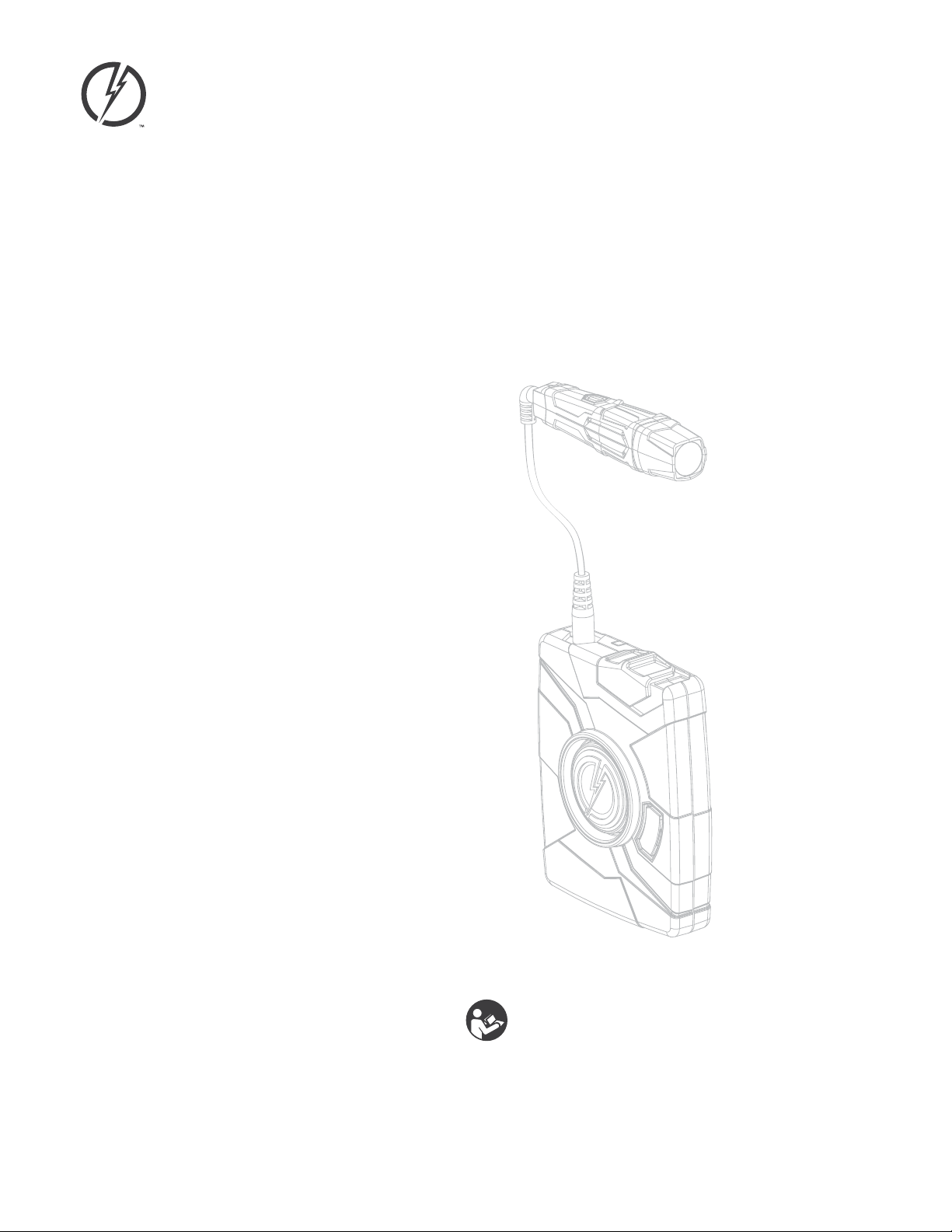
AXON Flex Camera
The camera is a digital video recorder (DVR) that oers high quality video and low-light gathering capabilities.
The recorder is designed to store at least 4 hours of video (and up to 13 hours based on the video setting). If the
camera is full (has reached its storage limit), the camera will not record over previous video but instead stops
recording.
Volume/Pairing Button
Imager
Bracket Clip
1 Volume/Pairing Button – This button is used to adjust the volume of audio prompts coming from the
camera. It also is used to pair the AXON Flex system with a smart phone; see Pairing AXON Flex Hardware
with Your Smart Device. This button does not control the volume of recorded audio.
2 Bracket Clip – A clamp attaches to this part of the camera, and the clamp can be attached to a variety of
mounting tools.
3 Imager – This is the camera lens. Avoid touching the lens. For cleaning information, see Chapter 10: Care
and Maintenance.
Hardware 2

6
Chapter 2 Hardware
AXON Flex Controller
The controller enables you to turn the unit on, begin recording of an event, stop recording, and turn the unit o.
The controller features LEDs to indicate the operating mode and battery capacity.
NOTE: You can turn o the controller LEDs, if necessary. See Turning o the Controller LEDs for instructions.
Top View
Front View
Operation LED
On/O Indicator
EVENT Button
Battery LED
Battery Button
On/O Switch
1 Operation LED – Shows the controller’s current operating mode:
Operation LED Operating Mode
Blinking Red Recording
Blinking Green Buering
Solid Red Booting Up
Blinking Yellow The Cable is Disconnected
NOTE: For the battery status, see the Battery LED, described below.
2 On/O Switch – Turns the controller on or o.
3 On/O Indicator – When the controller is turned on, the red portion of the controller is exposed. When the
controller is turned o, the red portion is covered from view.
4 EVENT Button – A double-press (quickly press twice) on the EVENT button takes the Flex system into
EVENT mode and begins recording video and audio (the Flex system can be congured without the audio
recording capability for locations where audio recording is restricted).
A 3-second press of the EVENT button takes the Flex system out of EVENT mode. The controller might take
several additional seconds to close out of the event video when it is taken out of EVENT mode.
7Chapter 2 Hardware
5 Battery LED – When pressed, momentarily indicates the remaining battery capacity only (it does not
indicate the operating mode).
Battery LED Controller Status
Green The Battery is Fully Charged.
Yellow The Battery Capacity is 20–40 Percent.
Red The Battery Capacity is LessThan 20 Percent.
When you turn the controller on, all LED lights turn solid red until the system is ready to use. Then the
Operation LED blinks green (BUFFERING mode) and the Battery LED goes out.
6 Battery Button – When pressed, momentarily indicates the remaining battery capacity only (it does not
indicate the operating mode).
Pressing buttons causes the AXON Flex system to emit audio alerts (beeps) to indicate system actions. See
Chapter 12: Audio Prompts for more information.
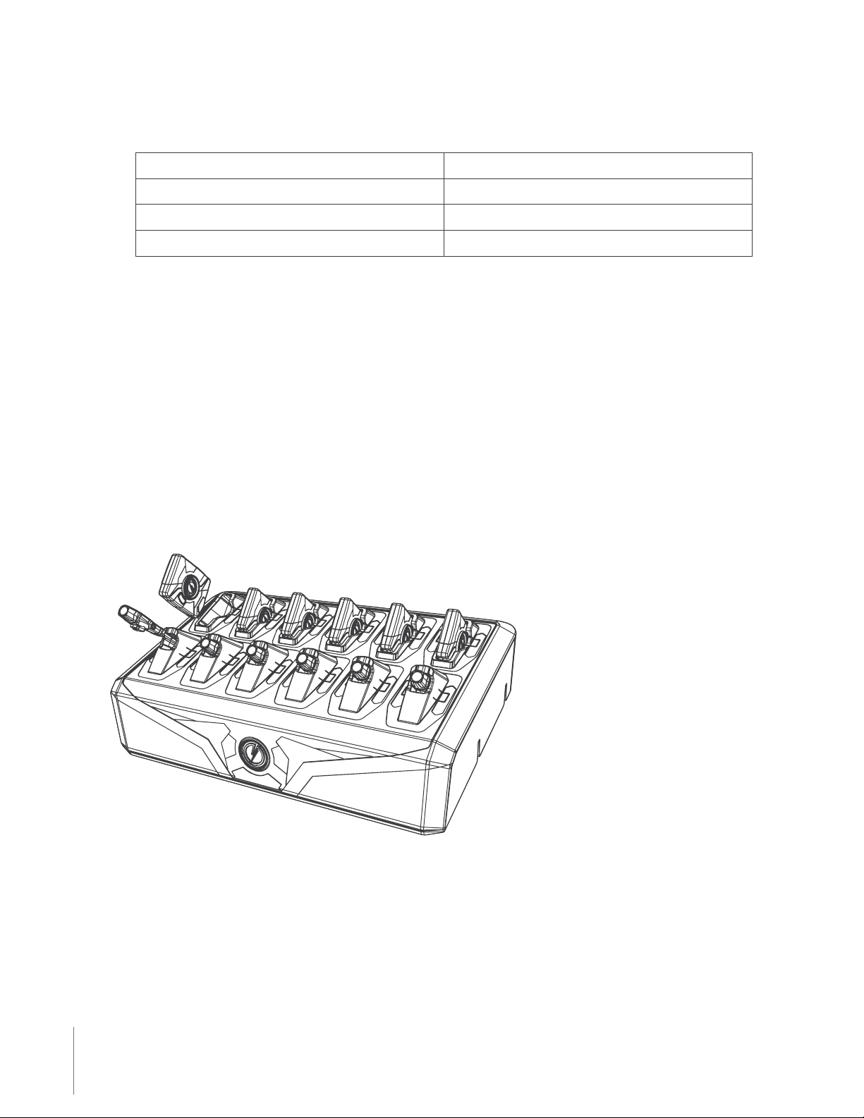
ETM System Components
AXON Flex ETM
The ETM can be placed on a table or mounted on a wall. It is designed to upload data from the camera to the
EVIDENCE.com website and recharge the controller.
ETM System Components
ETM Pucks
An ETM has 12 bays; each bay accepts a xture called a puck. There are two dierent puck designs; one for the
camera and another for the controller. An ETM is shipped with 6 camera pucks and 6 controller pucks installed
8
Chapter 2 Hardware
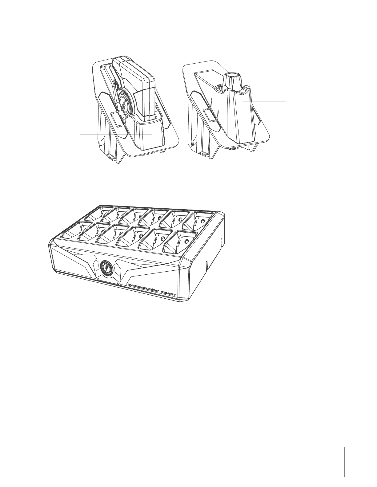
in the ETM. If desired, the pucks can be labeled with a user’s name to quickly identify user-specic controllers
and cameras.
Controller Puck
Camera Puck
Because the pucks are removable, you can customize your ETM to accept a dierent combination of components.
This can be useful for using the ETM to upload 12 cameras while using wall power sockets to recharge your
controllers. The drawing below shows an ETM with all pucks removed and ready for customization.
Equipment Mount Options
The AXON Flex system provides you with multiple ways to wear your camera and carry your controller. See
Chapter 5: Hardware Details for information on assembling the camera mounting systems.
Hybrid Holster
The controller can be carried in a holster that clips to your clothing or gear. Several clips are available for you to
place the controller in a way that best meets your needs.
9Chapter 2 Hardware
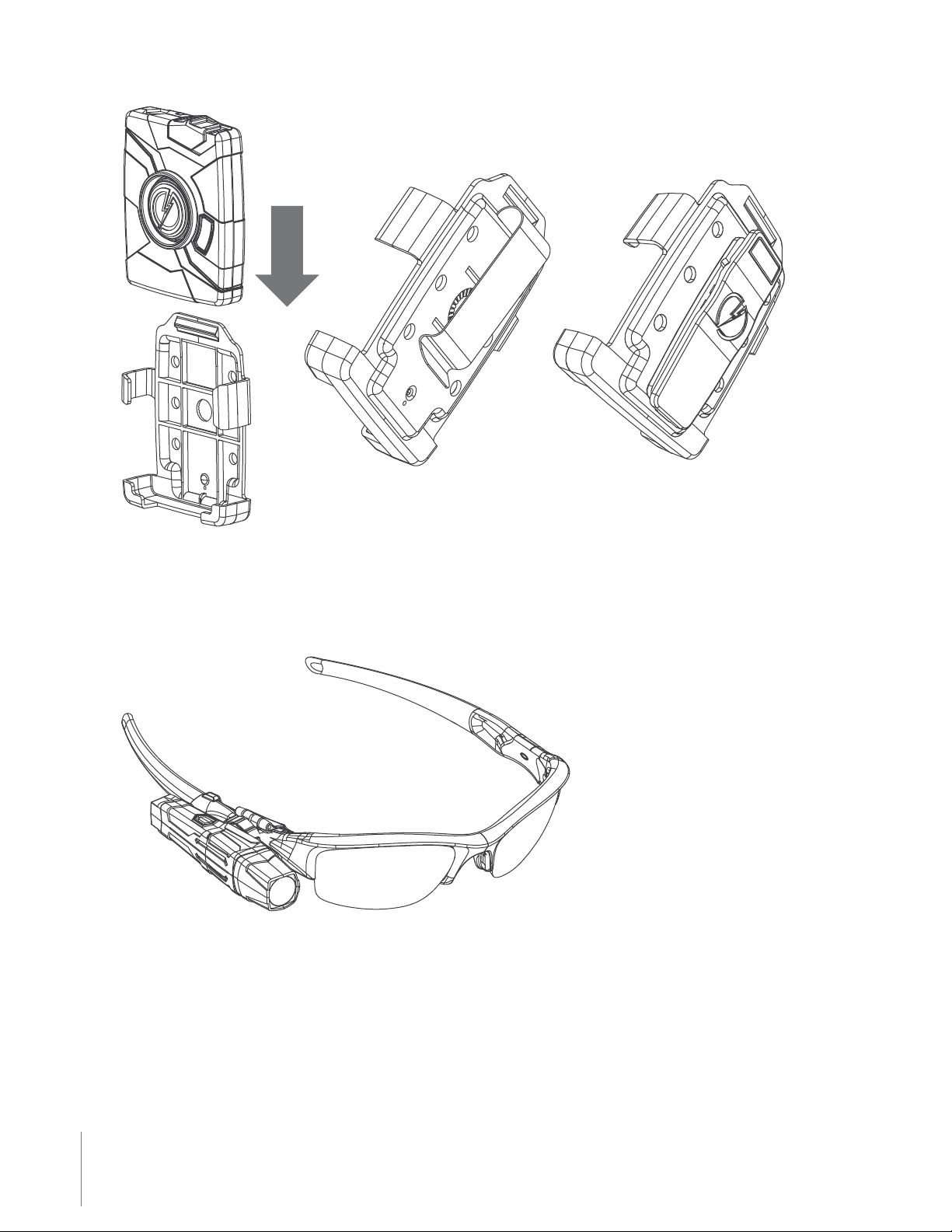
Oakley Eyewear Mount
The AXON Flex camera can be attached to Oakley Flak Jacket® glasses. With this system, the camera is designed
to directly capture your point of view because it is mounted at eye level.
Low Rider Headband
Designed for use with the Flex system, the Low Rider headband provides a comfortable frame to wear the
camera on your head. As with the Oakley eyewear mount, the Low Rider headband places the camera at your
eye level, and is designed to capture your perspective of the incident.

10
Chapter 2 Hardware
Hat Mount
The camera can be worn with headgear, including baseball caps. One magnetic clip is placed on the inside of the
baseball cap, while the rest of the assembly goes on the outside, held in place by magnetic attraction.
Collar Mount
The universal magnetic clip is compatible with most uniform shirt collars.

11 Chapter 2 Hardware
A collar support bar also is available. It consists of an inside magnetic clip combined with a metal band designed
to wrap underneath the collar, towards the back of the neck.

12
Chapter 2 Hardware
Epaulette Mount
If your uniform shirt has epaulettes, you can attach the AXON Flex camera to them.
The drawing shows the camera worn above the epaulette, but the mount can be positioned to place the camera
below the epaulette, if desired.
The epaulette mount also works with equipment vests.
13 Chapter 2 Hardware
Adhesive Mount
The adhesive mount allows the camera to attach to most smooth, hard surfaces.
NOTE: If you mount the camera to a helmet, please be advised that any after-market accessory or modication
to a motorcycle helmet could take that helmet out of compliance with federal regulations and safety standards.
Always follow your agency’s guidance and procedures for the use of motor vehicle equipment and helmets.
Equipment Connection Options
The controller and camera connect with cables specically designed for the AXON Flex system.

14
Chapter 2 Hardware
AXON Flex Cables and Connectors
To best suit your requirements, you can chose from straight or coiled cables, and straight or right-angle
connectors. The cables also come in varying lengths.
These cables are specically calibrated to work with the AXON Flex system. Use of unapproved cables
will degrade system performance and may cause the system to not function properly or at all.
Ensure that your cables are inserted properly into your AXON Flex camera and controller. If the camera’s
battery is low, and the cable is disconnected, your recorded video will be lost.
15 Chapter 2 Hardware
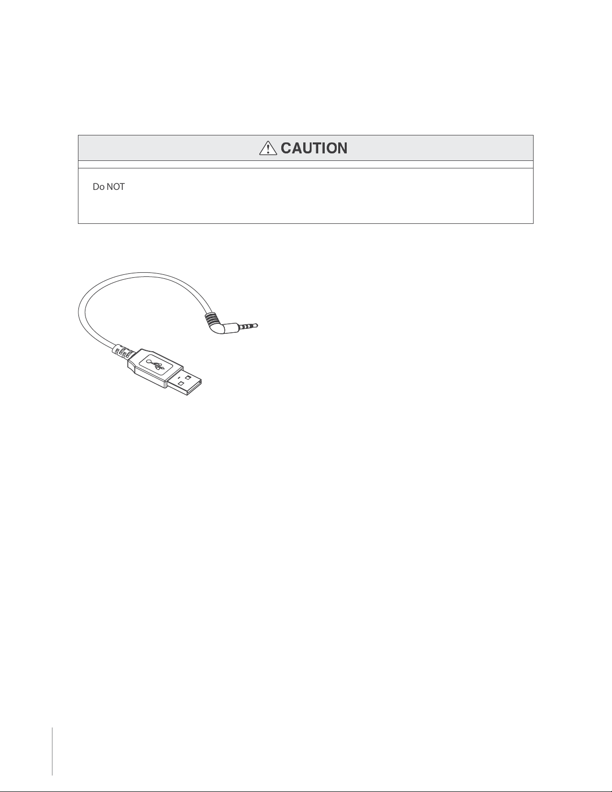
USB Cable
A USB cable is available to connect the AXON Flex camera directly to your computer.
Do NOT connect your AXON Flex camera to your computer before you have installed the EVIDENCE Sync
software.
EVIDENCE Sync software is required to download videos to your computer or upload videos to EVIDENCE.com.
See Chapter 3: Account Setup for EVIDENCE.com for more information.

21 Chapter 5 Hardware Details
Preparing the Magnetic Clip Assembly
The most basic way to mount the Flex camera to clothing involves two magnetic pieces. The two magnetic clips
pictured below are the foundation for many Flex camera mounting options. Each clip features a set of teeth on
one side and a ring on the other. The sides with teeth are magnetically attracted to each other.
The other clip can be placed inside a shirt collar or cap to hold the camera in place.

22
Chapter 5 Hardware Details
The magnetic clip is designed to allow some rotation up or down, so you can adjust the camera’s angle after it
is mounted on your shirt or cap.
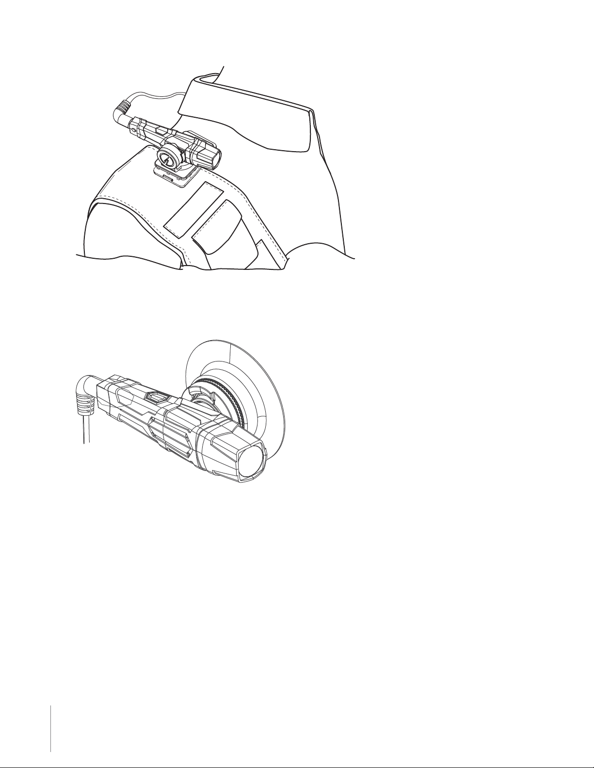
Mounting the Flex Camera to Your Shirt Collar
1 Push the two parts of the universal magnetic clip together on each side of your collar.
2 Tug on the parts slightly to conrm the connection is secure.
3 Attach the camera assembly to the magnetic clip on the outside of your shirt.

23 Chapter 5 Hardware Details
4 Tug on the parts slightly to conrm the connection is secure.
5 Route the cable to your controller. Ensure that the cable does not obstruct the motion of your head.
24
Basic Operations 6
Operating Modes
The AXON Flex system has two operating modes:
1 BUFFERING
2 EVENT
BUFFERING Mode
BUFFERING mode is the default mode of operation, and is activated a few seconds after turning on the controller.
The camera must be attached to the controller system in order for it to capture video in BUFFERING mode. If the
camera is not connected to the controller, you will not capture any video.
When BUFFERING begins:
t The Operation LED on the controller will blink green.
t The camera will be capturing video but no audio, and will not record to permanent memory while in
BUFFERING mode.
t Buered video duration is up to 30 seconds (00:00:30).
When you activate the EVENT mode, the buered video (not audio) captured directly before the event will be
saved and attached to the event in permanent memory. This feature is intended to capture the video of an
incident just before your activation of EVENT mode.
Because the system does not capture audio in BUFFERING mode, the rst 30 seconds of a recorded event
will be video-only. Buering mode starts only after the AXON Flex controller is turned on. The system
does not record when the controller is turned o.
EVENT Mode
To record an event or incident, double-press the EVENT button on the controller to activate the EVENT mode.
When EVENT mode is activated, the “buered”video directly preceding the event will be saved and attached to

25 Chapter 5 Basic Operations
the event recording. (Remember, the buered video will not contain audio.)
The moment you double-press the EVENT button, both video and audio will be recorded from the camera and
GPS coordinates (if the system is paired to a GPS-capable smart phone) will be recorded. This will continue
throughout the duration of the recording until you terminate the recording.
The AXON Flex hardware provides you with indications that it is recording in EVENT mode:
t At the start of an event and every two minutes during an event, the system will beep twice.
t The Operation LED on top of the controller will blink red.
The camera must be attached to the controller system in order for it to record video in EVENT mode. If the
camera is not connected to the controller, you will not record any video. If the camera becomes disconnected
from the controller during an event, the system will stop recording.
To exit EVENT mode and return to BUFFERING mode, press the EVENT button for approximately 3 seconds. The
3-second requirement reduces the possibility of accidentally exiting EVENT mode.
To end a recording and turn o the system, move the on/o switch to the“o”position. When you end a recording
with the on/o switch you will not go into BUFFERING mode, instead the system will turn o completely.
NOTE: An event not recorded by the AXON Flex system cannot be played back or downloaded to your computer.
Battery Status
Press the Battery button to determine the percentage remaining in the controller battery. See AXON Flex
Controller in Chapter 2: Hardware for details on the Battery LED functions.
Adjusting the Volume
Press the volume/pairing button on the camera to adjust the volume of the audio prompts.
Volume/Pairing Button
The volume has four settings. At each level, the camera beeps, providing you with a sample of the volume:
t Low
Other manuals for AXON FLEX
2
Table of contents
Other Taser Camera Accessories manuals


