Task Force 26133 User manual
TM
READ YOUR OPERATOR’S MANUAL COMPLETELY AND CAREFULLY BEFORE
ATTEMPTING TO SET UP OR OPERATE YOUR NEW REEL MOWER. ALL OPERATORS OF THIS
EQUIPMENT SHOULD READ AND UNDERSTAND ALL SAFETY RULES PRINTED ON THE MACHINE
AND IN THIS OPERATOR’S MANUAL BEFORE USE.
CAUTION - FOR YOUR SAFETY
NOTICE: On the nameplate of your machine you will find the serial number and MFG date code of your unit.
Please record these numbers on this manual cover for future service reference.
MFG. DATE ________ PURCHASE DATE: _________
PRINTED IN CHINA
Questions, problems, missing parts? Before returning to your retailer, call our customer
service department at 1-800-444-6742, 8:00 a.m.-6:00 p.m., EST, Monday-Thursday,
8:00 a.m.-5:00 p.m., EST, Friday.
16 in. REEL MOWER
ITEM / ARTICULO # 227682
MODEL / MODELO #26133

TABLE OF CONTENTS
………………………………………………………………………………….…………..…………………3
………………………………………………………………………….…………..…………………2
2
PRODUCT SPECIFICATIONS
PRODUCT SPECIFICATIONS
SAFETY INFORMATION
………………………………………………………………………….…………..……………….4/5
ASSEMBLY INSTRUCTIONS
CUTTING HEIGHT ADJUSTMENT
BLADE ADJUSTMENT
………………………………………………………………….…………..…………....…..
………………………………………………………………….…………..…………....…....................7
6
CARE AND MAINTENANCE
…………………………………………………………………………….…………..………………….3
CHECKING THE ADJUSTMENT
……………………………………………………………….…………..……………..........……7
…………………………………………………………………………….…………..……………………………
…………………………………………………………………………….…………..……………………………
…………………………………………………………………………….…………..…………………………………
…………………………………………………………………………….…………..……………………………….
…………………………………………………………………………….…………..…….....
TWO-YEAR LIMITED WARRANTY …………………………………………………………………….…………..…………………8
PARTS DIAGRAM ……………………………………………………………………………………………….…………..…….. 9/10
16 IN. REEL MOWER
Item No.
Cutting Path
Height Adjustments
Wheel Qty.
Weight
227682
16 in.
5/8 - 1- 7/8 in.
2
....17.6 Ib.

Never place hands, fingers or feet inside the reel. Although a motor does not power this mower, when the wheels turn
the reel spins and can cut.
Never mow when grass is wet as it can be slippery.
Do not use the reel mower while barefoot or while wearing sandals.
Walk behind, never run, while using reel mower. Always make sure of your footing when using this reel mower.
Never intentionally strike or hit trees, fences, etc. This can cause injuries or severely damage the reel mower
mechanisms.
Make sure your reel mower is in a safe operating condition. Do not attempt to operate this reel mower if damaged.
Contact customer service or have the reel mower repaired by a qualified repair service provider before using.
SAFETY INFORMATION
3
1. Minimum care is required to ensure smooth operation of your mower.
2. To avoid damage to mower or cutting blades, keep area to be mowed free from debris.
3. For best results, regularly apply lubricant to mower’s cutting surfaces, cutting reel axle shaft and wheels.
WARNING: Clean any grinding compound or debris from the cutter bar
blade, reel blade, pinions and pawls.
NOTE: Use industrial or valve lapping compound between 100–240 grit. Lubricate the axle and pinion with a light film of
wheel bearing grease.
CARE AND MAINTENANCE
6
4
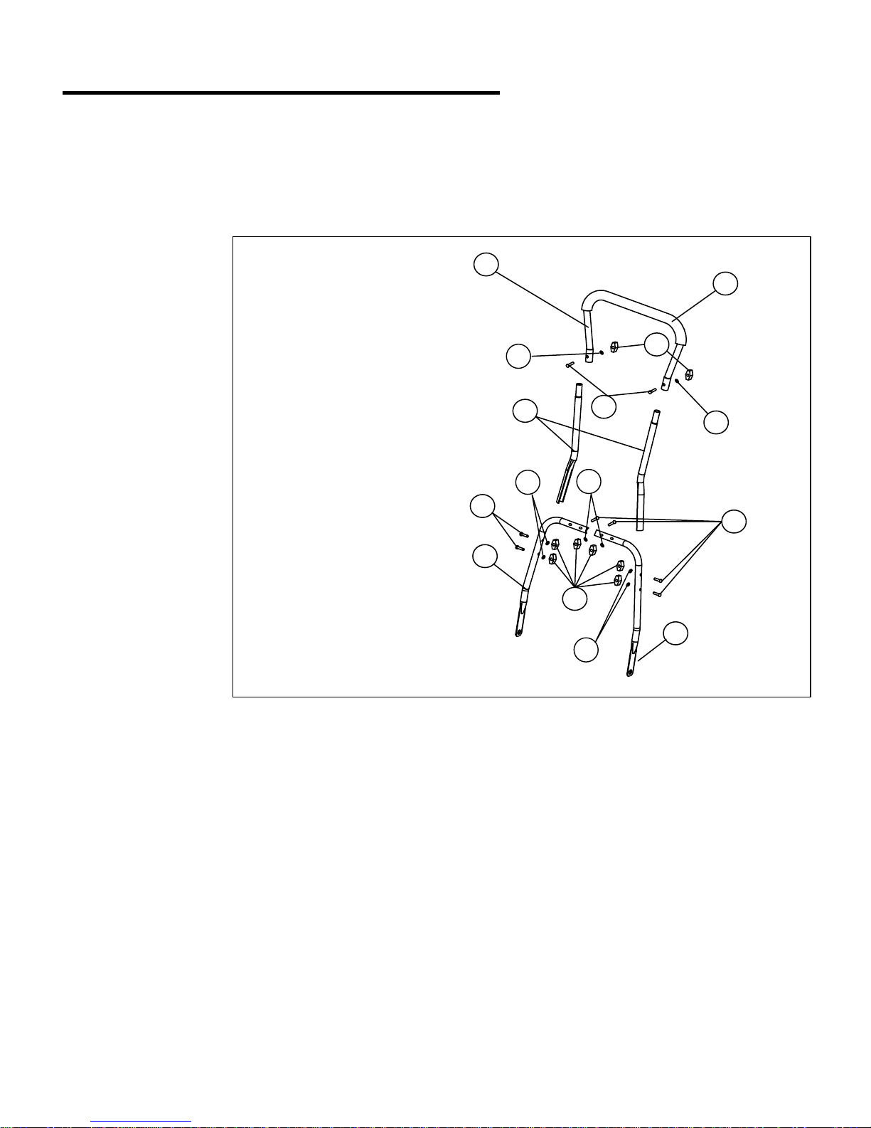
ASSEMBLY INSTRUCTIONS
1. Top handle
2. Center handle pieces
3. Left lower handle
4. Right lower handle
5. Foam grip
6. 1-
3/8 in. bolts
7. Flat washer
8. Wing nut
Tools Required
Pliers (Not included)
Fig. 1
ASSEMBLING THE HANDLE: (Fig.1)
NOTE: Do not completely tighten bolts until assembly is complete.
Before attempting to assemble, empty carton and compare parts with parts list below.
PACKING LIST
1-Top handle,
2-Center handle pieces,
2-Lower handle pieces,
8-Knobs,
8-Bolts,
8-Washers,
1-Reel mower body
Note:
• Carefully remove the parts from the box.
• Inspect the parts to make sure no breakage or damage occurred during shipping.
• Do not discard the packing material until all parts are examined.
• If any parts are damaged or missing, please call 1-800-444-6742 for assistance.
1. Insert the two center handle pieces (2) into the left and right side of the top handle (1) and secure with two
1- 3/8in. bolts (6) , flat washer (7) and wing nuts (8) provided.
2. Connect the right lower handle (4) with the left lower handle (3) and secure with two 1-3/8in. bolts (6), flat
washer (7) and wing nuts (8) provided.
3. Attach the top handle subassembly previously assembled, to the lower handle subassembly using four
1-3/8in. bolts (6),flat washer (7) and wing nuts (8) provided.
4. Tighten all the wing nuts on the joints of the handle assembly.
1
2
3
6
6
6
8
8
7
7
77
7
14
4
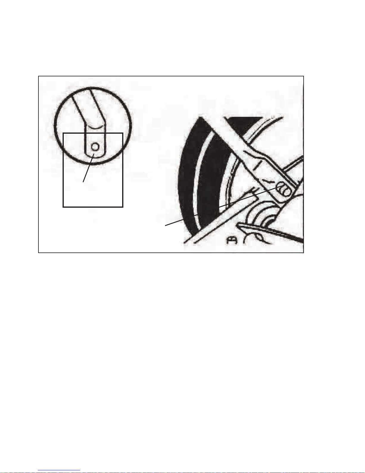
ATTACHING THE HANDLE TO THE MOWER BASE: (Fig.2)
1. Align holes (1) at the lower end of each handle arm with short posts (2) extending from
the
mower base side plates. Slide lower ends of handle arms onto posts.
5
Fig. 2
1
2
2. After handle arm holes are on posts, use pliers to snap C-clips (1) onto the slotted (2)
posts on both sides to secure handle.

CUTTING HEIGHT ADJUSTMENT: (Fig. 3)
OPERATION
6
Fig. 3
Height
adjustment nut
1. The cutting height of the 16 in. reel mower can be adjusted from 5/8 – 1-7/8 in. using the roller assembly.
2. For the lowest cutting position, loosen and remove the adjust ment nuts on both sides of roller assembly. Position
bolt through the bottom hole of the plastic roller bracket and top hole of the mower side plate.
3. For highest cutting position, loosen and remove the adjustment nuts on both sides of roller assembly. Position bolt
through the top hole of the plastic roller bracket and the bottom hole of the mower side plate.
4. For other cutting heights, position bolts through the preset height locations.

MOWER BLADE ADJUSTMENT: (Fig. 4)
WARNING: BLADES ARE EXTREMELY SHARP. TO AVOID INJURY, DO NOT TOUCH BLADES WHEN MAKING
ADJUSTMENT.
Note: Blades are factory adjusted.
CAUTION: Αdjusting the screws for blade adjustments is a very sensitive procedure. A turn of 1/16 is considered a major
adjustment. Βefore tightening one adjusting screw, make sure to loosen the opposite screw an equal amount.
1. Turn mower upside down.
2. Insert a piece of paper between cutter bar and reel blades, and slowly turn wheel by hand.
3. All blades should slice the paper evenly, along the entire length of the cutter bar while the reel turns smoothly.
4. If mower has an intermittent cut, adjustment should be made to the appropriate side of blades to attain proper cutting
action.
WARNING: Do not overtighten adjusting screws, as this could damage
cutter bar. Both screws must be tight on final adjustment.
CHECKING THE ADJUSTMENT
Fig. 4
7
• Misalignment can occur, often caused by blades being too loose or too tight. This can cause an uneven cut
or difficulty pushing the mower.
• Each end of the cutting bar is adjusted separately.
• To move the blades closer to the cutting bar turn the adjustment nuts clockwise. To move the blades away from the
cutting bar turn the adjustment nuts counterclockwise.
OPERATION
Cutting bar blade
adjustment nut

TWO-YEAR LIMITED WARRANTY
The manufacturer warranties that this product is free from defects in material and workmanship for
two (2) years from the date of the original purchase by the original purchaser only.
THIS WARRANTY IS NOT TRANSFERABLE AND DOES NOT COVER:
Products sold damaged or incomplete, sold “as is”, sold reconditioned or used as rental
equipment.
Delivery, installation or normal adjustments explained in the owner’s manual.
Damage or liability caused by shipping, improper handling, improper installation, incorrect
voltage or improper wiring, improper maintenance, improper modification, or the use of
accessories and/or attachments not specifically recommended.
Repairs necessary because of operator abuse or negligence, or the failure to install, operate,
maintain and store the product according to the instructions in the owner’s manual.
Damage caused by cold, heat, rain, excessive humidity, corrosive environments and materials,
or other contaminants.
Expendable items that become worn during normal use.
Cosmetic defects that do not interfere with tool functionality.
Freight costs from customer to vendor.
Repair and transportation costs of products or parts determined not to be defective.
ANY INCIDENTAL, INDIRECT OR CONSEQUENTIAL LOSS, DAMAGE, OR EXPENSE THAT
MAY RESULT FROM ANY DEFECT, FAILURE OR MALFUNCTION OF THE PRODUCT.
Some states do not allow the exclusion or limitations on how long an implied warranty lasts, so
the above limitations may not apply to you. This warranty gives you specific legal rights, and
you may have other rights that vary from state to state.
WARRANTY REPLACEMENT PARTS are available by calling the toll free number, 1-800-444-6742
8
8:00 a.m.-6:00 p.m., EST, Monday-Thursday, 8:00 a.m.-5:00 p.m., EST, Friday.
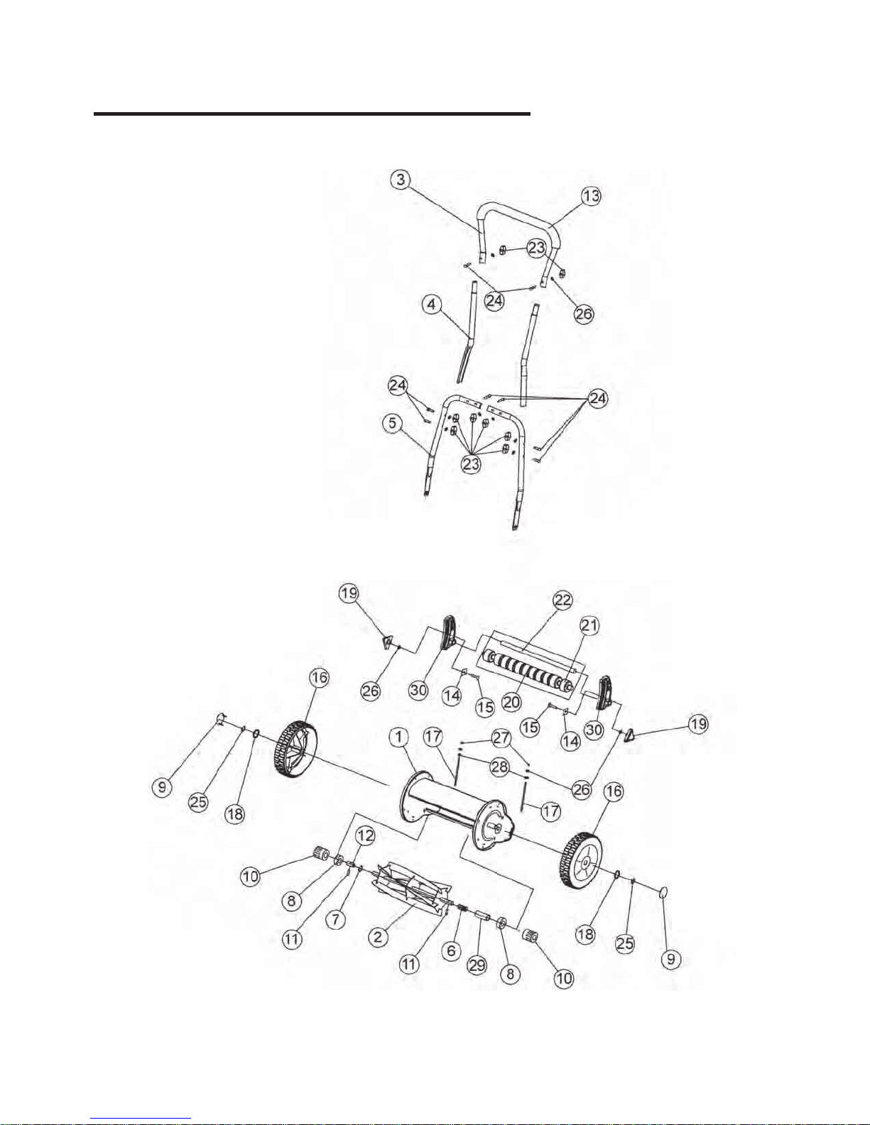
PARTS DIAGRAM
9

PARTS DIAGRAM LIST
Item Description Qty
1 Housing 1
2 Reel blades 1
3 Top push handle 1
4 Center handle pieces 2
5 Lower handle 2
6 Spring 2
7 Spring washer 2
8 Bearing 2
9 Wheel cover 2
10 Gear wheel 2
11 Pin 2
12 Shaft 1
13 Foam grip 1
14 Washer 2
15 Bolt 2
16 Wheel 2
17 Cutting bar adjustment lever 2
18 Flat washer 2
19 Height adjustment knob 2
20 Long rear roller 1
21 Short rear roller 2
22 Long shaft 1
23 Knob 8
24 Bolt 8
25 C-clip 2
26 Flat washer 10
27 Locked nut 2
29 2
30
Shaft
2
Cutting height adjustment
10
Table of contents
Other Task Force Lawn Mower manuals


