TATA Motors TSW Series Quick start guide

MANUALE DI
INSTALLAZIONE
USO E
MANUTENZIONE
INSTALLATION,
USE AND
MANTEINANCE
MANUAL
ITALIANO / ENGLISH
Emissione / Issue Sostituisce / Replaces
09.05 06.04
TSW 18÷151
Serie / Series
2
TSW 18 ÷ 151
0. ELENCO DOCUMENTI ALLEGATI
Elencodocumentazionefornitaacorredodellamacchina
facente parte integrante del presente manuale.
- Quaderno tecnico
- Manuale microprocessore
- Certificato di garanzia
- Dichiarazione di conformità
- Schemi elettrici specifici
0. LIST OF ATTACHMENTS
List of documents supplied with the unit and forming
an integral part of this manual.
- Technical book
- Microprocessor manual
- Certificate of guarantee
- Declaration of conformity
- Specific electrical circuit

3
TSW 18 ÷ 151
INDICE CONTENTS
Argomento
ELENCO DOCUMENTI ALLEGATI
PREMESSA
Informazioni generali
Allegati
Avvertenze
DESCRIZIONE DELLA MACCHINA
Identificazione
Identificazione della macchina
Destinazione d'uso
Controindicazioni
Descrizione generale
SICUREZZA
Definizioni
Regole generali di sicurezza
Simbologia
Mappa dei segnali di sicurezza
Segnali di sicurezza
Dispositivi di emergenza e di sicurezza
Descrizione del rischio residuo
Rischio residuo in prossimità della macchina
Misure da adottare in caso di fuoriuscita di
gas frigorigeno
Operazioni con rimozione dei pannelli
ISPEZIONE, TRASPORTO
Ispezione
Stoccaggio
Sollevamento e trasporto
Disimballo
INSTALLAZIONE
Scelta del luogo di installazione
Collegamento idraulico
Generalità
Evaporatore
Subject
LIST OF ATTACHMENTS
INTRODUCTION
General information
Attachments
Warnings
UNIT DESCRIPTION
Identification
Identification
Intended use
Contraindications
General description
SAFETY
Definition
General safety regulations
Symbols
Location of safety signs
Safety signs
Emergency and safety devices
Description of residue risks
Residue risks near the unit
Measures to take in case of leaking refrige-
rant gas
Operations with the panels removed
INSPECTION AND TRANSPORT
Inspection
Storage
Lifting and transport
Unpacking
INSTALLATION
Choosing the installation site
Water connections
General
Evaporator
0
1
1.1
1.2
1.3
2
2.1
2.1.1
2.2
2.3
2.4
3
3.1
3.2
3.3
3.3.1
3.3.2
3.4
3.5
3.5.1
3.5.2
3.5.3
4
4.1
4.2
4.3
4.4
5
5.1
5.2
5.2.1
5.2.2
0
1
1.1
1.2
1.3
2
2.1
2.1.1
2.2
2.3
2.4
3
3.1
3.2
3.3
3.3.1
3.3.2
3.4
3.5
3.5.1
3.5.2
3.5.3
4
4.1
4.2
4.3
4.4
5
5.1
5.2
5.2.1
5.2.2

4
TSW 18 ÷ 151
Collegamenti elettrici
Generalità
Collegamento elettrico del flussostato/pres-
sostato differenziale
Collegamento elettrico della pompa di circolazione
Consensi esterni
AVVIAMENTO
Controlli preliminari all'avviamento
Messa in funzione
Verifiche durante il funzionamento
Generalità
Sbrinamento
(Solo unità pompa di calore)
Arresto del gruppo
FUNZIONAMENTO
Generalità
Fermata stagionale
RICERCA GUASTI
MANUTENZIONE E CONTROLLI PERIODICI
Avvertenze
Generalità
Controlli mensili
Controlli quadrimestrali
Riparazioni del circuito frigo
Rabbocchi di refrigerante
DISMISSIONE E SMALTIMENTO
5.3
5.3.1
5.3.2
5.3.3
5.3.4
6
6.1
6.2
6.3
6.3.1
6.3.2
6.4
7
7.1
7.2
8
9
9.1
9.1.1
9.1.2
9.2
9.3
10
Electrical connections
General
Electrical connections to the flow switch/dif-
ferential water pressure switch
Electrical connections to the circulation pump
External signals
START UP
Preliminary controls
Start up
Checks during unit operation
General
Defrosting
(Only heat pump units)
Stopping the unit
OPERATION
General
Seasonal shut down
TROUBLE SHOOTING
ROUTINE MAINTENANCE AND CONTROLS
Warnings
General
Monthly controls
Four-monthly controls
Repairing the refrigerant circuit
Topping up the refrigerant liquid
SHUT DOWN AND DISPOSAL
5.3
5.3.1
5.3.2
5.3.3
5.3.4
6
6.1
6.2
6.3
6.3.1
6.3.2
6.4
7
7.1
7.2
8
9
9.1
9.1.1
9.1.2
9.2
9.3
10
5
TSW 18 ÷ 151
1. PREMESSA
1.1 INFORMAZIONI GENERALI
Questo manuale contiene le norme di installazione, uso
e manutenzione dei refrigeratori TSW, evidenziandone
rischi e pericoli connessi. Esso è stato espressamente
studiato e sviluppato per permettere al personale pre-
posto un utilizzo facile e in sicurezza dei refrigeratori
d’acqua TSW. Leggere attentamente e completamente
tutteleinformazioniinessoriportate.Prestareparticolare
attenzione alle norme evidenziate con
in quanto se non osservate possono causare danno alle
persone, all’ambiente e/o alla macchina stessa.
La società declina ogni responsabilità per qualsiasi uso
improprio della macchina, per modifiche alla stessa
non autorizzate o per la non osservanza delle norme
riportate sul manuale.
Il manuale deve essere conservato in un luogo sicuro e
messo a disposizione del personale addetto alla con-
duzione ed alla manutenzione del refrigeratore.
1.2 ALLEGATI
Fanno parte integrale del presente manuale i documenti
evidenziati a pag. 2.
1.3 AVVERTENZE
Le unità TSW sono state progettate e costruite per
garantire nel tempo grande affidabilità di esercizio e
massima sicurezza; per questo e grazie alle scelte pro-
gettuali e realizzative, la società può garantire la totale
conformità agli standard di sicurezza CE.
Ulteriore garanzia è assicurata dai collaudi cui la mac-
china è stata sottoposta in fabbrica.
All’utente resta quindi soltanto l’impegno di un uso
proprio e di una manutenzione preventiva conforme alle
indicazioni contenute in questo manuale.
Ogni intervento, di qualsiasi natura, sulla
macchina deve essere preceduto da una
attenta lettura del presente manuale in tutte
le sue parti.
1. INTRODUCTION
1.1 GENERAL INFORMATION
This manual contains the installation, use and mainte-
nance instructions for the TSW chillers, and highlights
all connected risks and perils. It has been expressly
prepared and written to allow authorised users to use
the TSW water chillers in complete safety and with the
greatest of ease. Please read the whole of this manual
with care, paying special attention to the sections
marked with
as non-compliance may cause harm to people, dete-
riorate the environment and/or damage the unit.
Thecompany declines all responsibilityfor any improper
use of the unit, unauthorised modifications or non-com-
pliance with the instructions contained in this manual.
Please keep this manual in a safe place and make it
available to chiller operators and maintenance men.
1.2 ATTACHMENTS
The documents shown on page 2 form an integral part
of this manual.
1.3 WARNINGS
The TSW units have been designed and built to ensure
long-term operating reliability and maximum safety;
for this reason and thanks to the company’s design
and construction policy, the company is able to guar-
antee that this product totally complies with EC safety
standards.
A further guarantee of this is provided by the factory
tests carried out on the unit.
The user, therefore, must only ensure the unit is properly
used and that maintenance operations are carried out
according to the indications contained in this manual.
Theunitshouldnotbetoucheduntilthewhole
of this manual has been carefully read.

6
TSW 18 ÷ 151
Il manuale di installazione, uso e manuten-
zione deve essere sempre a disposizione
degliaddetti,iquali, prima di ogni operazione
sulla macchina, devono obbligatoriamente
leggerlo.
This installation, use and maintenance man-
ual must always be kept within easy reach
of authorised staff who are obliged to read
it before carrying out any operations on the
unit.
7
TSW 18 ÷ 151
2 DESCRIZIONE DELLA MACCHINA
Questo capitolo ha lo scopo di fornire una descrizione
generale delle caratteristiche principali della macchina
nel suo insieme, unitamente a quella dei principali com-
ponenti, standard e opzionali.
2.1 IDENTIFICAZIONE
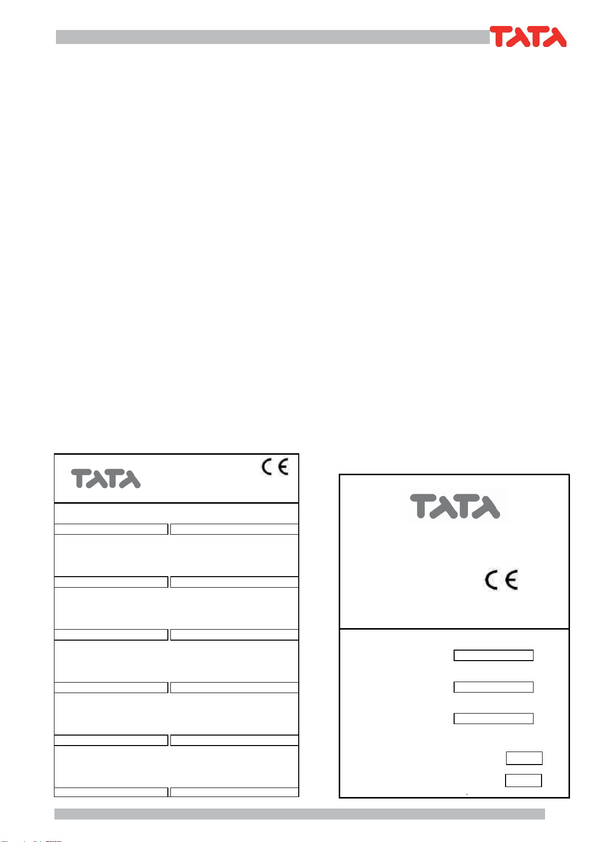
2.1.1 Identificazione della macchina
La macchina si identifica tramite le targhette poste sul
telaio e sul quadro elettrico. Le targhette riportano i
seguenti dati:
- Ragione sociale dell'Azienda
- Indirizzo dell'Azienda
- Designazione della serie e del tipo di unità
- Numero di matricola
- Anno di costruzione
- Tipo e quantità di refrigerante
- Massima pressione ammissibile
- Taratura dei pressostati
- Simbolo della certificazione CE
- Caratteristiche elettriche
- Identificazione schema elettrico
2 UNIT DESCRIPTION
This chapter contains a general description of the main
unit characteristics, together with those of its principal
standard and optional components.
2.1 IDENTIFICATION
2.1.1 Unit identification
The unit can be identified throug the plats attached on
the frame and in the electrical box. This label contains
the following information:
- Manufacturer’s name
- Manufacturer’s address
- Description of the series and type of unit
- Series number
- Year of construction
- Type and quantity of refrigerant liquid
- Max. Allowable pressure
- Pressure switch set point
- EC certification symbol
- Electrical characteristics
- Wiring diagram identification
Modello/Model Matricola/Serial number
Modell/Modèle Matrikelnr/Matricule
Tensioni-Fasi-Frequenza Tensioni circuiti ausiliari
Voltage-Phases-Frequency Auxiliary circuit voltage
Spannung-Phasen-Frequenz Hilfstromkreisspannung
Tel. 0438 2661
Fax. 0438 266380
Tension-Phases-Fréquence Tension circuits auxiliaires
V
Corrente massima assorbita Corrente massima di spunto
Web: www.tata.it
Max absorbed current Max starting current
Maximale Stromaufnahme Max Anlaufstrom
Courant maxi absorbée Courant maxi de démarrage
AA
Modello/Model
Tipo di refrigerante Carica refrigerante per circuito
Modell/Modèle
Refrigerant type Refrigerant charge per circuit
Kältemittel Typ Kältemittelfüllung pro Kreislauf
Matricola/Serial number
Type de réfrigerant Charge de réfrigerant chaque circuit
Matrikelnr/Matricule
kg
Taratura pressostato di alta Press. massima circuito idraulico
Anno di costruzione
High pressure switch setting Max hydraulic circuit pressure
Construction year
HD-Wächter Einstellung Max. Druck im hydraul. Kreislauf
Baujahr
Préssion maxi refrigerant Préssion maxi circuit hydraulique
Année de fabrication
Bar Bar
Gruppo del fluido frigorifero Data di produzione
PS Max.Press.ammissibile
Group of the refrigerant fluid Manufacturing date
Max Working press.Refrig.side
Kältemittel Klasse Herstellungsdatum
Max Betriebsdruck Kältemittelseitug
Groupe de fluide frigorifique Date de fabrication
Press.max.de travail cute refrigerant
28 bar
20 bar
ALTA
HIGH PRESS.
HOCHDUCK
HAUTE
BASSA
LOW PRESS.
NIEDERDUCK
BASSE
28 bar
20 bar
ALTA
HIGH PRESS.
HOCHDUCK
HAUTE
BASSA
LOW PRESS.
NIEDERDUCK
BASSE
28 bar
20 bar
ALTA
HIGH PRESS.
HOCHDUCK
HAUTE
BASSA
LOW PRESS.
NIEDERDUCK
BASSE
28 bar
20 bar
ALTA
HIGH PRESS.
HOCHDUCK
HAUTE
BASSA
LOW PRESS.
NIEDERDUCK
BASSE
bar
bar
ALTA
HIGH PRESS.
HOCHDUCK
HAUTE
BASSA
LOW PRESS.
NIEDERDUCK
BASSE
TATA S.p.A
Via Europa
31020 S.Fior (TV) - ITALY
TATA S.p.A
Via Europa
31020 S.Fior (TV) - ITALY

8
TSW 18 ÷ 151
2.2 DESTINAZIONE D’USO
I TSW sono refrigeratori con condensazione ad acqua
destinatiaraffreddareacqua(eventualmenteaddizionata
con glicole etilenico inibito) che circola in un anello chiu-
so. Le unità a pompa di calore possono, a seconda del
ciclo di funzionamento scelto, raffreddare o riscaldare
l’acqua dell’anello.
Le unità a recupero di calore , possono, come sottopro-
dotto, riscaldare dell’acqua che circola in un secondo
anello chiuso.
Ilcaldo,oilfreddo,cosìprodottopuò essere utilizzato per
impianti di climatizzazione o per processi industriali.
2.3 CONTROINDICAZIONI
Non impiegare in prossimità della macchina
prodotti infiammabili.
Non impiegare in prossimità della macchi-
na sostanze in grado di formare miscele
esplosive.
Non impiegare la macchina dove sussistono
problemi di impatto ambientale (vedi punto
3.5 pag. 12).
2.4 DESCRIZIONE GENERALE
Tuttele strutture sonorealizzate in acciaio saldato e pro-
tetto tramite verniciatura a polveri poliestere. Gli schemi
funzionali e la componentistica usata sono allegati.
2.2 INTENDED USE
TheTSWseriesof water condensation chillers have been
designed to cool water (possibly containing inhibited
ethylene glycol) circulating in a closed circuit. The heat
pumpunitscan cool or heat the waterintheclosed circuit
depending on which operating cycle is chosen.
The heat recovery units can also heat the water circulat-
ing in a second closed circuit.
The heat or cold produced can be used for air-condi-
tioning systems or industrial processes.
2.3 CONTRAINDICATIONS
Do not use inflammable products near the
unit.
Do not use substances that can form ex-
plosive mixtures near the unit.
Do not use the unit in conditions that could
be harmful for the environment (see point
3.5 on page 12).
2.4 GENERAL DESCRIPTION
All the unit structures are made from steel and are
protected with polyester powder paints. The functional
diagrams and the components used are attached to
this manual.
9
TSW 18 ÷ 151
3 SICUREZZA
3.1 DEFINIZIONI
In questo documento verranno utilizzate le seguenti
definizioni:
- Zone pericolose: qualsiasi zona all’interno e/o in
prossimità della macchina in cui la presenza di una
personaesposta costituisca un rischio perla sicurezza
e la salute di detta persona.
- Persona esposta: qualsiasi persona che si trovi inter-
namente o in parte in una zona pericolosa.
- Operatore/Manutentore: la o le persone incaricate di
far funzionare, regolare, eseguire la manutenzione,
riparare, movimentare la macchina.
3.2 REGOLE GENERALI DI SICUREZZA
È vietato alle persone non autorizzate avvi-
cinarsi alla macchina.
Prima di ogni intervento di manutenzione
sulla macchina, seguire scrupolosamente
quanto indicato nel capitolo 9 a pag. 28.
È vietata la rimozione delle protezioni e
l’esclusione dei dispositivi di sicurezze e di
emergenza.
È vietato stazionare sulla macchina.
- Impiegare la macchina solo per l’uso a cui essa è
destinata.
- Il costruttore non risponde dei danni derivanti da un
impiego improprio della macchina o da modifiche
tecniche effettuate sulla macchina.
- Controllare regolarmente se i dispositivi di sicurezza
presentano un funzionamento corretto.
- Non smontare, modificare o mettere fuori funzione
parti della macchina.
- Per tutti gli interventi da effettuare sulla macchina,
utilizzare esclusivamente attrezzi ed equipaggiamenti
idonei e in buone condizioni. Gli operatori dovranno
indossare i normali dispositivi di protezione individuali
(guanti, casco, occhiali, ecc.).
3SAFETY
3.1 DEFINITION
This document uses the following definitions:
- Dangerous areas: any area inside and/or near to the
unit in which the presence of a person would give rise
to a risk for that person’s health.
- Exposed person: anyone who is wholly or partly inside
a dangerous area.
- Operator/Maintenance man: person or persons au-
thorised to operate, adjust, service, repair or move
the unit.
3.2 GENERAL SAFETY REGULATIONS
It is forbidden for unauthorised persons to
approach the unit.
Scrupulously observe the contents of Chap-
ter 9 on page 28 before carrying out each
maintenance operation on the unit.
It is forbidden to remove safety guards and
by-pass safety and emergency devices.
It is forbidden to stand on the unit.
- Only use the unit to do what it was built for.
- Themanufacturerdeclinesallresponsibilityfordamage
deriving from improper use or technical modifications
made to the unit.
- Check the safety devices are in perfect working order
on a regular basis.
- Do not dismount, modify or disconnect unit parts.
- When working on the unit, only use suitable tools and
equipment in good condition. Operators must wear
normalpersonalprotectionequipment(gloves,helmet,
goggles, etc.).
10
TSW 18 ÷ 151
- I lavori sull’equipaggiamento elettrico devono essere
eseguiti solo da un elettricista qualificato.
- Gli interventi sul circuito frigorifero possono essere
effettuati solo da personale specializzato.
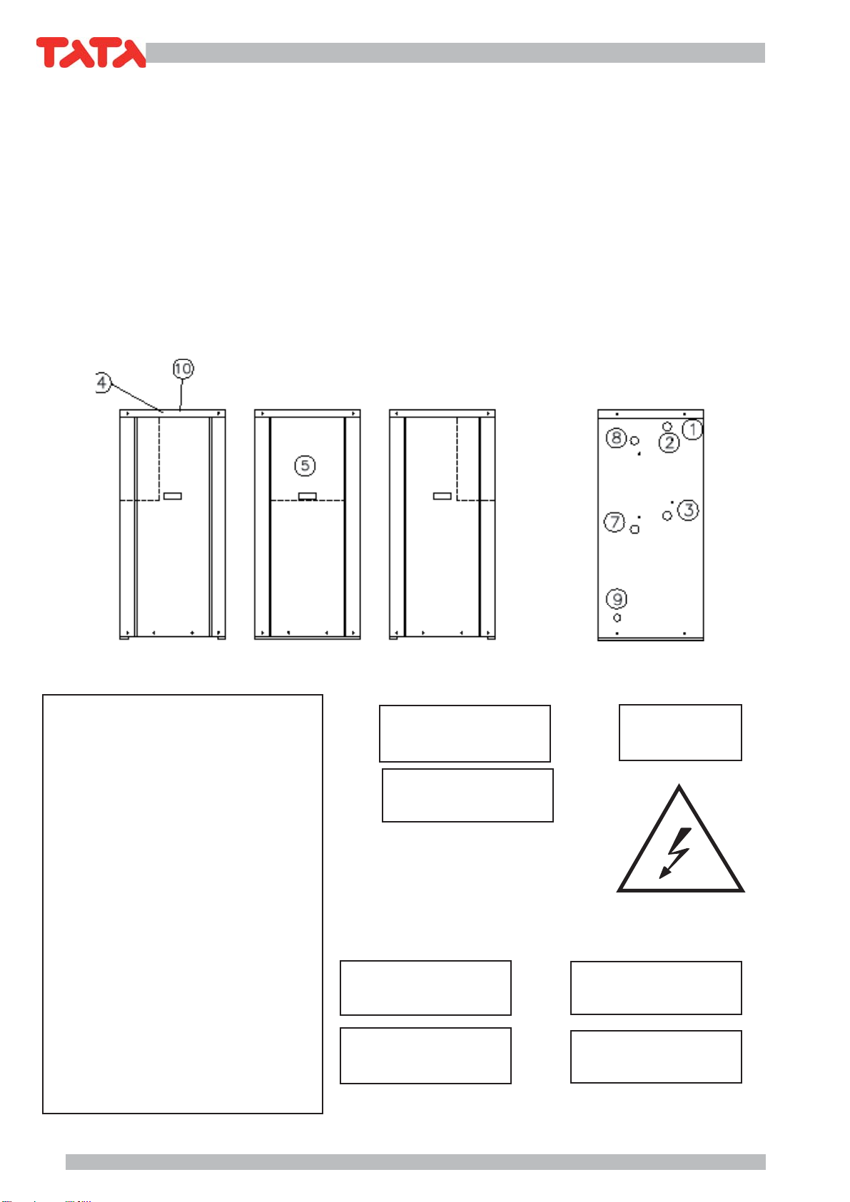
3.3 SIMBOLOGIA
Verificare periodicamente lo stato delle targhette e
provvedere, in caso di necessità, al loro ripristino.
3.3.1 Mappa dei segnali di sicurezza
3.3.2 Segnali di sicurezza
- Work on the electrical system of the unit may only be
carried out by a qualified electrician.
- Work on the refrigerant circuit may only be carried out
by specialised staff.
3.3 SYMBOLS
Check the state of the plates on a regular basis and
repair them if necessary.
3.3.1 Location of safety signs
3.3.2 Safety signs
ATTENZIONE
• DARE TENSIONE AI RISCALDATORI OLIO DEL CARTER ALMENO 12 ORE PRIMA
DELL’AVVIAMNETO DELL’UNITÀ NEGLI INTERVALLI DI FUNZIONAMENTO (AD
ES. PAUSA DEL FINE SETTIMANA) TOGLIERE L’ALIMENTAZIONE ELETTRICA.
• L’UNITÀ È MUNITA DI UN RITARDATORE ANTIRICIRCOLO E DI DISPOSITIVO PER
LA RIPARTENZA AUTOMATICA.
• PRIMA DI APRIRE IL SEZIONATORE FERMARE L’UNITÀ AGENDO SUGLI APPOSITI
INTERRUTTORI DI MARCIA O IN ASSENZA SUL COMANDO A DISTANZA.
• PRIMA DI ACCEDERE A PARTI INTERNE DELL’UNITÀ TOGLIERE TENSIONE
APRENDO IL SEZIONATORE GENERALE.
WARNING
• SUPPLY THE CRANKCASE HEATERS AT LEAST 12 HOURS BEFORE STARTING
THE UNIT DURING TEMPORARY STOP PERIODS (LIKE WEEK÷ENDSI NEVER
DISCONNECT ELECTRICAL SUPPLY TO THE UNIT.
• THE UNIT IS PROVIDED WITH DELAY RELAY AND WITH AUTOMATIC RESTART
DEVICE.
• BEFORE OPENING THE MAIN SWITCH, STOP THE UNIT BY ACTING ON THE
SUITABLE RUNNING SWITCHES OR THESE ARE IF NOT PRESENT, ON THE
REMOTE CONTROL.
• BEFORE SERVICING THE INNER COMPONENTS, DISCONNECT ELECTRICAL
SUPPLY BY OPENING THE MAIN SWITCH.
ACHTUNG
• DIEKURBELWANNENHEIZUNGMINDESTENS12STUNDENVORDERINBETRIEB-
NAHMEDESGERATSUNTERSPANNUNGSETZEN DIE KURBELWANNENHEIZUNG
WAHREND DER STILLSTANDSZEITEN DES GERATS NICHT AUSSCHALTEN.
• DAS GERAT IST MIT SCHALTVERZOGERUNGSTIMER UND VORRICHTUNG FÜR
AUTOMATISCHEN WIEDERANLAUF AUSGESTATTET.
• VOR DEM OFFNEN DES HAUPTSCHALTERS SETZEN SIE DAS GERAT DURCH
BETATIGUNGDERENTSPRECHENDENBETRIEBSSCHALTERODERWENNDIESE
NICHT VORHANDEN SIND, DURCH FERNBEDIENUNG AUSSER BETRIEB.
• BEVOR MAN DIE INTERNE GERATEKOMPONENTEN BERUHRT. MUSS DER
HAUPTSCHALTER GEOFFNET WERDEN.
NOTICE
• FOURNIR TENSION AUX RECHAUFFERS DU CARTER AU MOINS 12 HEURES
AVANT QUE L’UNITÉ SOIT DÉMARÉE NE COUPEZ PAS LA TENSION AUX
RÉCHAFFEURS PENDANTS DES COURTES PERIODES D’ARRET DE L’UNITE.
TELS QUE LE WEEK-END.
• L’UNITÉ EST EQUIPPÉE DE RELAIS ANTI COURT-CYCLE ET D’UN DISPOSITIF
POUR LE REDEMARRAGE AUTOMATIQUE.
• AVANTD’OUVRIRLESÉCTIONNEURGENERALARRETEZ L’UNITÉ EN AGISSANT
SUR LES INTERRUPTEURS DE MARCHE OU AU CAS OU IL N’YA PAS SUR LE
COMMENDE Á DISTANCE.
• AVANT DE TOUCHER LES COMPOSANT INTERNES A L’UNITÉ, COUPER LA
TENSION EN OUVRANT LE SECTIONNEUR GÉNÉRAL.
INGRESSO ACQUA REFRIGERATA
CHILLED WATER INLET
KALTWASSEREINTRITT
ENTRÉE EAU GLACÉE
USCITA ACQUA REFRIGERATA
CHILLED WATER OUTLET
KALTWASSERAUSTRITT
SORTIE EAU GLACÉE
INGRESSO ACQUA CONDENSAZIONE
CONDENSER WATER INLET
VERFLÜSSIGERWASSEREINTRITT
ENTRÉE EAU CONDENSEUR
USCITA ACQUA CONDENSAZIONE
CONDENSER WATER OUTLET
VERFLÜSSIGERWASSERAUSTRITT
SORTIE EAU CONDENSEUR
SFIATO ARIA
AIR PURGE
ENTLÜFTUNGSVENTIL
PURGE AIR
12
3
7
8
4
9
5
INGRESSO TENSIONE DI LINEA
ELECTRIC CABLE ENTRY
SPANNUNGSLEISTUNGSEINTRITT
ENTRÉE CABLE ALIMENTATION
RUBINETTO DI SCARICO
DRAINING VALVE
ENTLEERUNGSHAHN
SOUPAPE DE DECHARGE
10

11
TSW 18 ÷ 151
3.4
DISPOSITIVI DI EMERGENZA E DI SICUREZZA
Un dispositivo di emergenza che tolga tensione
dalla macchina deve essere previsto all’esterno
della stessa a cura di chi installa la macchina.
3.5 DESCRIZIONE DEL RISCHIO RESIDUO
La descrizione del rischio residuo prende in consider-
azione i seguenti elementi:
- a quale tipologia di pericoli è soggetto chi opera nel-
l’ambito della macchina;
- la descrizione dei principali pericoli;
- chi può essere esposto a tali pericoli;
- quali sono le principali misure di sicurezza adottate
per ridurre il rischio di infortuni.
Le indicazioni per la prevenzione degli infortuni di seguito
riportate,conriferimentoallerelativeareearischioresiduo,
devono essere integrate con tutte le indicazioni generali
del presente capitolo e con le norme di prevenzione in-
fortuni vigenti nel paese di destinazione dell’impianto.
3.5.1 Rischio residuo in prossimità della macchina
- Folgorazione,senonvengonoeffettuaticorrettamentel’al-
lacciamento elettrico e la messa a terra della macchina.
- Tagli o escoriazioni per la presenza di superfici taglienti.
- Aspirazioneesuccessivadispersioneinambientedelle
sostanze presenti sul luogo dell’installazione.
- Fuoriuscita di acqua (in caso di anomalia).
- Formazione di acqua di condensa e di ghiaccio nella
zona antistante la macchina durante il funzionamento
in riscaldamento delle macchine a pompa di calore.
- Alterazione del microclima (durante il funzionamento).
- Emissione di rumore (durante il funzionamento). I livelli
di pressione sonora delle singole unità sono riportati
sul quaderno tecnico
- Fuoriuscita di olii (per anomalia).
- Fuoriuscita del frigorigeno (per anomalia).
N.B. Il frigorigeno è una sostanza ad effetto serra. Si
trattadi vapori piùpesanti dell’aria eche possono
provocare soffocamento riducendo l’ossigeno
disponibileperlarespirazione.Unarapida evapo-
razione del liquido può causare congelamento.
3.5.2 Misure da adottare in caso di fuoriuscita di
gas frigorigeno
-Tipo di prodotto: R407C
- Misure di pronto soccorso:
Informazione generale:
non somministrare alcunchè a persone svenute.
Inalazione:portare all’aria aperta. Ricorrereall’ossige-
no o alla respirazione artificiale se necessario. Non
somministrare adrenalina o sostanze similari.
Contatto con gli occhi:
sciacquare accuratamente ed abbondantemente con ac-
qua per almeno 15 minuti e rivolgersi ad un medico.
Contatto con la pelle:
Lavaresubitoabbondantementeconacqua.Togliersi
immediatamente tutti gli indumenti contaminati.
- Misure in caso di fuoriuscita accidentale:
Precauzioni individuali:
evacuare il personale in aree di sicurezza. Prevedere una
ventilazione adeguata. Usare mezzi di protezione personali.
Precauzioni ambientali: evapora.
Metodi di pulizia: evapora.
3.4 EMERGENCY AND SAFETY DEVICES
An emergency external circuit breaker must
be fitted by the unit installer to disconnect
the unit from the power supply.
3.5 DESCRIPTION OF RESIDUE RISKS
The description of residue risks includes the following
elements:
- the kind of danger the people working on the unit are
subjected to;
- description of the main dangers;
- who is exposed to such dangers;
- the main safety methods used to reduce the risk of
injury.
The following accident prevention instructions, with
reference to the relative areas concerned by residue
risks, must be integrated with all the general indications
contained in the present chapter and with the accident
prevention regulations in force in the country of instal-
lation.
3.5.1 Residue risks near the unit
- Electrocution if the unit is not properly corrected to
the mains power supply and earth circuit.
- Cuts or abrasions caused by sharp surfaces.
- Extractionandsubsequentdispersionintheenvironment
of substances present in the installation site.
- Leaking water (in case of malfunction).
- Formation of condensation and ice in front of the unit
while the unit heat pumps are working.
- Alteration of the micro climate (during operation).
- Noise (during operation).The sound pressure levels of
each unit are carried in technical manual.
- Leaking oil (in case of malfunction).
- Leaking refrigerant liquid (in case of malfunction).
N.B. Refrigerant liquid is a substance which causes a
greenhouse effect. Its vapours are heavier than
air and can cause suffocation by reducing the
amount of oxygen available for breathing. Rapid
evaporation of the liquid can cause freezing to
occur.
3.5.2 Measures to take in case of leaking
refrigerant gas
- Product type: R407C
- First aid measures:
General information:
Do not give anything to people who have fainted.
Inhalation: take the person out into the open air. Use
oxygen or artificial respiration if necessary. Do not
give adrenaline or similar substances.
Contact with eyes:
carefully rinse with abundant water for at least 15
minutes and see a doctor.
Contact with the skin:
Wash with abundant water and remove all contami-
nated clothing immediately.
- Measures to take in case of accidental leaking:
Personal precautions:
evacuate all staff to safety areas. Make sure the area is
suitably ventilated. Use personal protection equipment.
Environmental precautions: the gas evaporates.
Cleaning methods: the gas evaporates.
12
TSW 18 ÷ 151
3.5.3 Operazioni con rimozione dei pannelli
Alcune delle operazioni e/o verifiche di seguito descritte
richiedono la rimozione dei pannelli del refrigeratore per
accedere all’interno dello stesso.
Prima di rimuovere qualsiasi pannello pe-
rimetrale, eccezion fatta per quello che
protegge il quadro elettrico, è obbligatorio
togliere tensione.
Si fa presente che all’interno dell’unità, anche a mac-
china ferma possono esserci superfici calde (tubazioni,
compressore, ecc.), o fredde (compressore, separatore
d’aspirazione, ecc.), taglienti (alette batterie) o corpi in
movimento (ventilatori).
Pertanto tali operazioni devono essere ef-
fettuate solo da personale qualificato che
indossi indumenti di sicurezza.
Verifiche di funzionamento possono richiedere
il funzionamento (totale o parziale dell’unità)
con un pannello aperto. In tal caso il pannello
va rimosso a macchina ferma.
Queste verifiche sono particolarmente peri-
colose e sono pertanto riservate a personale
altamente qualificato.
Operare come segue:
- Togliere tensione tramite l’interruttore generale.
- Aprire il quadro elettrico e disattivare, togliendo i
relativi fusibili, gli organi di cui non è necessario il
funzionamento per la verifica che si deve effettuare.
- Richiudere il quadro elettrico.
- Rimuovere il pannello interessato.
- Avviare l’unità.
- Effettuare le verifiche richieste con la massima cautela
e con l’utilizzo di protezioni individuali.
- Completate le verifiche, arrestare l’unità e rimettere al
suo posto il pannello precedentemente tolto.
- Togliere tensione e rimettere al loro posto gli eventuali
fusibili precedentemente tolti.
- Richiudere il quadro elettrico.
3.5.3 Operations with the panels removed
Someof the following operationsand/orcontrols require
the panels of the unit to be removed in order to access
the inside of the unit.
Before removing an outer panel, except for
the one protecting the electrical panel, the
unit must be disconnected from the mains
power supply.
Please note that some surfaces inside the unit may be
hot(piping,compressor,etc.), cold (compressor, suction
separator, etc.), sharp (coil fins) or moving (fans) even
when the unit is not working.
These operations may only be carried out by
qualified staff wearing safety clothing.
Operating checks may require the unit to work (totally
or partially) while a panel is open. In this case the panel
should be removed when the unit is not working.
These checks are particularly dangerous
and may only be carried out by highly qual-
ifi
ed staff.
Proceed as follows:
- Turn off mains power with the main power switch.
- Openthe electrical panel and removethe relative fuses
to disconnect the components that do not need to be
working in order to carry out the relative check.
- Close the electrical panel.
- Remove the panel in question.
- Start the unit.
- Carry out the relative check with the greatest of care
and using personal protection equipment.
- After completing the check, stop the unit and put the
panel back in place.
- Turn off mains power and put back any fuses that
were previously removed.
- Close the electrical panel.

13
TSW 18 ÷ 151
4. ISPEZIONE, TRASPORTO
4.1 ISPEZIONE
All’atto del ricevimento dell’unità, verificarne l’integrità.
Poiché la macchina è stata accuratamente controllata
prima di lasciare la fabbrica, eventuali danni sono da
imputare al trasportatore. Si raccomanda perciò di
annotarli sul Foglio di Consegna prima di controfir-
marlo. Avvisare tempestivamente la società o l’Agente
sull’entità del danno riportato dall’unità. Il Cliente deve
sempre compilare un rapporto scritto che riguarda ogni
eventuale danno subito dalla macchina.
4.2 STOCCAGGIO
La temperatura dell’ambiente in cui vengono immagaz-
zinate le unità deve essere compresa tra -20 e +50°C.
4.3 SOLLEVAMENTO E TRASPORTO
Durante lo scarico ed il posizionamento dell’unità, prestare
molta attenzione alle manovre che non devono in alcun
modo essere brusche e/o violente. Non utilizzare come
punti di sollevamento le tubature o altri componenti della
macchina.
Attenzione!
Intutte le operazioni disollevamento assicu-
rarsi di aver ancorato saldamente l’unità per
evitare ribaltamenti o cadute accidentali.
4.4 DISIMBALLO
L’imballo va tolto solo quando l’unità è giunta sul posto di
installazioneenondovràpiùesseremovimentata.Rimuovere
con cura l’imballo della macchina, evitando di danneggiare
la stessa. Poiché i materiali che costituiscono l’imballo
sono di natura diversa (legno, polietilene(PE), polistirolo,
cartone, ecc.), si consiglia di conservarli separatamente
e di consegnarli alle ditte specializzate nello smaltimento
e nel riciclaggio degli stessi allo scopo di salvaguardare
l’ambiente.
4. INSPECTION AND TRANSPORT
4.1 INSPECTION
Check the condition of the unit on receipt. As the unit
was carefully checked before leaving the factory, any
claims for damages should be addressed to the for-
warder. Any damage should therefore be indicated on
the Delivery Note before signing it. Please inform the
company or the Agent of the nature of the damage to
the unit immediately.The Customer must always write a
report describing any damage caused to the unit.
4.2 STORAGE
The temperature in the area where the units are stored
must range between -20 and +50°C.
4.3 LIFTING AND TRANSPORT
Whenunloading and positioning the unit, take greatcare
not to make sudden and/or violent manoeuvres. Do not
lift the unit by its piping or any other components.
Attention!
Make sure the unit is securely anchored
before lifting it in order to prevent it from
accidentally overturning or falling.
4.4 UNPACKING
Only unpack the unit when it has reached the installa-
tion site and no longer needs to be moved. Remove the
packing material with care, making sure not to damage
the unit. Given that various kinds of packing materials
are used (wood, polyethylene(PE), polystyrene, card-
board, etc.), they should be separated and delivered
to specialised disposal and recycling companies for
environmental reasons.
P U N T I D I S O L L E V A M E N T O
L I F T I N G P O I N T S
H E B E N P U N K T E N
P O I N T D E S O U L E V E M E N T
P U N T I D I S O L L E V A M E N T O
L I F T I N G P O I N T S
H E B E N P U N K T E N
P O I N T D E S O U L E V E M E N T

14
TSW 18 ÷ 151
5 INSTALLAZIONE
5.1 SCELTA DEL LUOGO DI INSTALLAZIONE
Nella scelta del luogo di installazione si dovrà tenere
conto di:
- Peso dell’unità:
Lasoletta di appoggiodell’unità deve essere
perfettamenteorizzontaleedingrado di sop-
portare il peso in funzionamento dell’unità.
Èopportunocostruireunasolettadisupportodidimen-
sioni proporzionate all’unità. Ciò si rende in particolar
modo necessario quando l’unità deve essere posta su
terreno instabile (giardini, terreni di riporto, ecc.).
La soletta deve:
• appoggiaresuopportune fondamenta,avereun’altezza,
rispetto al terreno circostante, di circa 10-15 cm;
• essere orizzontale ed in grado di sopportare circa
il 200% del peso di esercizio della macchina. Si
consiglia di interporre una guarnizione di sughero
adeguatamente sigillata lungo il perimetro.
- Spazi:
Ènecessarioverificare che gli spazi dirispetto
riportatisulquaderno tecnico dell’unità siano
lasciati liberi.
Ridurre lo spazio richiesto può significare difficoltà o im-
possibilità di effettuare le operazioni di manutenzione.
Tutta la zona di rispetto dovrà essere in-
terdetta, fatta eccezione per gli operatori e
manutentori addetti alla macchina.
- Rumore:
Durante il suo funzionamento, l’unità genera del rumore,
evitare pertanto l’installazione in ambienti riverberanti.
- Vibrazioni:
Benché le macchine trasmettano al terreno un basso livello
di vibrazioni, è in ogni caso consigliabile frapporre fra il ba-
samento delle stesse ed il piano di appoggio un nastro di
gomma rigido.
Quando si rende necessario un isolamento maggiore è
opportuno l’utilizzo di supporti antivibranti (in gomma o
a molla
5.2 COLLEGAMENTO IDRAULICO
5.2.1 Generalità
Perla realizzazione delcircuito idraulico dell’acqua refri-
gerataèbuonanormaseguireattentamenteleindicazioni
sotto riportate oltre che la normativa vigente.
Attenzione!
Le tubazioni idrauliche devono essere op-
portunamente staffate per non gravare con
il loro peso sul refrigeratore.
- Raccordare le tubazioni al refrigeratore tramite giunti
flessibilialfinedievitare la trasmissione delle vibrazioni
e compensare le dilatazioni termiche.
- Installare sulle tubazioni i seguenti componenti:
• valvole di intercettazione (saracinesche) per isolare
l’unità dal circuito idraulico;
• indicatori di temperatura e pressione per la normale
manutenzione e controllo del gruppo;
5 INSTALLATION
5.1 CHOOSING THE INSTALLATION SITE
When choosing the installation site the following points
should be considered:
- The weight of the unit:
The supporting surface under the unit must
be perfectly horizontal and able to withstand
its operating weight.
A supporting surface with an appropriate area should
be built. This is particularly important if the unit is in-
stalled on unstable ground (gardens, embankments,
etc.).
The supporting surface must:
• lie on suitable foundations and be about 10-15 cm
higher than the surrounding ground;
• be horizontal and able to withstand about 200%
of the weight of the unit in operation. A suitable
sealed layer of cork should be placed along the
perimeter.
- Spaces:
Make sure that sufficient free space, as in-
dicated on the technical book, is left around
the unit.
Less space will make it difficult or impossible to carry
out maintenance operations.
People may not enter the unit area unless
they are authorised operators and mainte-
nance personnel.
- Noise:
The unit generates noise while it’s working; do not
install it in reverberating rooms.
- Vibrations:
Although the units transmit a low level of vibrations
to the ground, a sheet of rigid rubber should always
be placed between the unit base and the supporting
surface.
Ifgreater insulation is required,vibration moisting sup-
ports should be used (in rubber or with springs).
5.2 WATER CONNECTIONS
5.2.1 General
Please carefully carry out the following instructions and
observe current law when installing the chilled water
circuit.
Attention!
The water pipes must be suitably supported
with brackets in order not to weigh on the
chiller.
- Connect the pipes to the chiller with flexible joints in
order to prevent the transmission of vibrations and to
compensate thermal expansion.
- Install the following components on the pipes:
• shut-off valve (moisters) for shutting off the water
mains;
• temperature and pressure gauges for routine main-
15
TSW 18 ÷ 151
•
pozzetti sulle tubazioni d’ingresso ed uscita per i rilievi di
temperatura, qualora non fossero presenti indicatori di tem-
peratura;
•
filtro metallico (tubazione in ingresso) a rete con
maglia non superiore ad 1mm, per proteggere lo
scambiatore da scorie o impurità presenti nelle
tubazioni;
• valvoledisfiato,da collocare nelle parti più elevatedel
circuito idraulico, per permettere lo sfogo dell’aria;
• vaso di espansione, (se non già presente)
dimensionato in funzione della quantità
d’acqua contenuta nell’impianto e delle
escursioni termiche prevedibili, e valvole
di carico automatica per il mantenimento
della pressione del sistema e compensare
le dilatazioni termiche del fluido.
•
rubinetto di scarico e, ove necessario, serbatoio di dre-
naggioperpermettere lo svuotamento dell’impiantoper
le operazioni di manutenzione o le pause stagionali.
Attenzione!
È indispensabile installare un flussostato di
sicurezza (se non già presente il flussostato/
pressostatodifferenziale) su un trattorettilineo
di tubazione ad una distanza dall’uscita dello
scambiatore pari a non meno di 8-10 volte il dia-
metrodellatubazionestessa. In caso contrario la
garanzia viene a decadere immediatamente.
5.2.2 Evaporatore
È di importanza fondamentale che l’ingresso dell’ac-
quaavvengaincorrispondenzadellaconnessionecon-
trassegnata con la targhetta“ENTRATA ACQUA”.
Per gli attacchi idraulici vengono utilizzate connessioni filettate
maschio o flangiate, a seconda dei modelli (fare riferimento ai
disegni dimensionali, così come per la posizione degli attac-
chi).
È di fondamentale importanza realizzare il circui-
to idraulico in modo tale che venga garantita la
costanza della portata d’acqua allo scambiatore
in qualsiasi condizione di funzionamento.
Poichéla richiesta frigoriferadell’utenza non coincide general-
mentecon quella erogata daicompressori,l’azione degli stessi
èmolto spesso intermittente. Negli impianti a bassocontenuto
d’acqua, dove l’effetto di inerzia termica della stessa è meno
sensibile, è opportuno verificare che il contenuto dell’impianto
soddisfi la seguente relazione:
V > P/45n
dove:
V = volume d’acqua (litri)
P = potenza resa dall’unità (Watt)
n = numero di gradini di parzializzazione.
Se non vengono raggiunti i volumi sopraccitati, è necessario pre-
vedere un serbatoio d’accumulo tale che, sommato alla capacità
dell’impianto, venga raggiunto il valore fornito dalla relazione ripor-
tenance and inspection purposes;
•
check points on the inlet and outlet pipes for meas-
uring temperatures if temperature indicators are not
fitted;
• metalfilter(inletpipe)witha maximum mesh aperture
of 1 mm to protect the exchanger from waste or
impurities in the pipes;
• relief valves, fitted in the uppermost parts of the
water circuit, for expelling air;
• expansion tank (if not already fitted) of a
suitable size for the quantity of water con-
tained in the system and the expected tem-
perature range, and an automatic inlet valve
for maintaining the pressure of the system
and compensating the thermal expansion
of the fluid.
• drain valve or, where necessary, drain tank for
emptying the circuit for maintenance operations or
seasonal shut downs.
Attention!
Asafetyflow switch hastobeinstalled(if the flow
switch/differentialwaterpressure switch arenot
already fitted) along a straight section of piping
at a distance from the exchanger outlet of not
less than 8-10 times the diameter of the piping.
Theguaranteewillimmediatelybecomenulland
void if the above is not complied with.
5.2.2 Evaporator
It is vitally important that the water enters
the unit from the connection point marked
with the “WATER INLET” plate.
Threaded or flanged male unions, depending on the mod-
els, are used to make water connections (please refer to
the scale drawings which also show the position of the
unions).
It is vitally important to connect the water
circuit so that the flow of water to the ex-
changer is always constant under all oper-
ating conditions.
As the demand for cooling by utilities does not generally
coincide with what is delivered by the compressors, they
often work intermittently. In units with a low water content,
where the effect of thermal inertia is not felt so much, the
system should be checked to make sure it satisfies the
following relation:
V > P/45n
where:
V = volume of water (litres)
P = power capacity of the unit (Watts)
n = number of capacity steps.
Iftheabovevolumesarenotobtained, a storage tank should
be installed so as to satisfy the above relation when added
to the capacity of the system.This tank requires no special
16
TSW 18 ÷ 151
tata. Tale serbatoio non richiede particolari accorgimenti, salvo che,
allo stesso modo delle tubature dell’acqua refrigerata, va isolato al
fine di non penalizzare la resa dell’impianto e di evitare fenomeni di
condensazione.
È buona norma installare una valvola di sicu-
rezza sul circuito idraulico (se non già presen-
te). In caso di anomalie gravi nell’impianto (ad
es. incendio) essa permetterà di scaricare il
sistema evitando possibili scoppi. Collegare
sempre lo scarico ad una tubazione di diame-
tro non inferiore a quello dell’apertura della
valvola, e convogliarlo in zone nelle quali il
getto non possa recare danno alle persone.
Attenzione!
Duranteleoperazionidiallacciamento idrau-
lico non operare mai con fiamme libere in
prossimità o all’interno dell’unità.
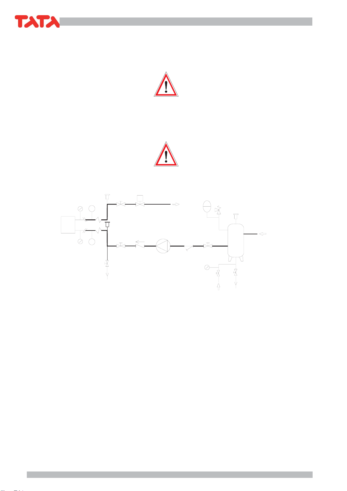
1 = Giunti antivibranti
2 = Valvola di intercettazione a sfera
3 = Valvola di ritegno
4 = Pompa di circolazione
5 = Filtro a rete
6 = Gruppo di carico acqua automatico
7 = Vaso di espansione chiuso
8 = Valvola di sicurezza
9 = Serbatoio di accumulo acqua
10= Termometri
11= Sfiato aria automatico
12= Manometro
E = Evaporatore
features; it just needs to be isolated, just like the chilled
water pipes, so as not to affect the performance of the
system and to prevent the formation of condensation.
A safety valve should be installed on the
water circuit (if not already fitted). In case
of serious system faults (e.g. fire) this will
allow the system to be drained in order to
prevent the risk of explosions. Always con-
nect the drain to a pipe with a diameter not
less than that of the valve opening and install
the outlet in an area where the jet cannot
cause harm to people.
Attention!
While connecting the water circuit, never
work with naked flames near to or inside
the unit.
1 = Vibration-proof joints
2 = ball shut-off valve
3 = Check valve
4 = Circulation pump
5 = Mesh filter
6 = Automatic water filling valve
7 = Closed expansion tank
8 = Safety valve
9 = Water storage tank
10= Thermometers
11= Automatic air purge
12= Pressure gauge
E = Evaporator
-
6
6
!
.
"
#
$
'
&
%

17
TSW 18 ÷ 151
5.3 COLLEGAMENTI ELETTRICI
5.3.1 Generalità
Queste operazioni devono essere effettuate
solo da personale specializzato.
Prima di effettuare qualsiasi operazione su
parti elettriche assicurarsi che non vi sia
tensione.
Verificare che l’energia disponibile corrisponda ai dati nomi-
nali dell’unità riportati sulla targhetta (tensione, numero di fasi,
frequenza). L’allacciamento avviene tramite cavo tripolare più
terra. I collegamenti elettrici devono essere effettuati seguendo
attentamentele istruzioniriportatesullo schemaelettricoallegato
all’unità. Il collegamento a terra è obbligatorio per legge. Si
deve perciò provvedere al collegamento del cavo di terra con la
barra di terra situata nel quadro elettrico e contrassegnata con
PE.L’alimentazione del circuito ausiliario è derivata dalla linea di
potenza tramite un trasformatore situato nel quadro elettrico.
La sezione del cavo e le protezioni di linea
devono essere conformi a quanto indicato
nelloschemaelettricoenell’appositascheda
allegata all’unità.
Rispettare la sequenza delle fasi, viceversa la macchina
non potrà funzionare. La tensione di alimentazione non
deve subire variazioni superiori a ±5% e lo squilibrio tra
le fasi deve essere sempre inferiore al 2%.
Il funzionamento deve avvenire entro i valori
sopra citati, pena la decadenza immediata
della garanzia.
5.3.2
Collegamento elettrico della pompa di circolazione
La pompa di circolazione(se non già istallata) deve
sempre essere collegata al controllo dell’unità come
previsto dallo schema elettrico.
La pompa deve essere avviata prima della
partenza del refrigeratore e fermata dopo
l’arresto di quest’ultimo (ritardo minimo
consigliato: 40 secondi).
5.3.3 Consensi esterni
Qualora si desideri effettuare un ON-OFF remoto dell’unità
è necessario collegare il consenso esterno ai contatti in-
dicati sullo schema elettrico. Per il collegamento elettrico
al contatto ON-OFF remoto e funzionamento CHILLER-
POMPADICALOREremoto,noninstallare i cavi di comando
all’interno delle canaline usate per i cavi di potenza; nel
caso non fosse possibile, utilizzare un cavo schermato.
Quandosi effettuano icollegamenti descritti
ai paragrafi 5.3.2 - 5.3.3 attenersi scrupolo-
samente a quanto riportato nello schema
elettrico.Icavidicollegamentodevonoavere
sezione minima di 1,5 mm².
5.3 ELECTRICAL CONNECTIONS
5.3.1 General
These operations may only be carried out
by specialised staff.
Before carrying out any operations on elec-
trical components, make sure the unit is dis-
connected from the mains power supply.
Make sure that the mains power supply corresponds to the
rated values of the unit shown on the plate (voltage, number
of phases, frequency). The unit must be connected with a
three-pole cable plus earth. Electrical connections must
be made carefully following the instructions shown on the
wiring diagram attached to the unit. The earth connection
is obligatory by law. The earth cable must be connected to
the earth bar located in the electrical panel and marked with
PE. Auxiliary circuit power is supplied by the power line by
means of a transformer located in the electrical panel.
The cross-section of the cable and the line
protectionsmustcomplywiththeindications
shown on the wiring diagram and in the rela-
tive sheet attached to the unit.
Observe the phase sequence, otherwise the unit will
not work. Input voltage must not exceed variations of
over ±5% and phase unbalance must always be less
than 2%.
Unitoperation must always take placewithin
theabove values as otherwise the guarantee
will immediately become null and void.
5.3.2 Electrical connections to the circulation pump
The circulation pump must always be connected to the
unit control system as shown on the wiring diagram.
The pump must be started up before starting
up the chiller while it must be stopped after
the chiller has stopped (minimum recom-
mended delay: 40 seconds).
5.3.3 External signals
If a remote ON-OFF command is required, connect the
external enable to the contacts shown on the wiring
diagram. For the electrical connection to the remote
On-off contact and remote Chiller heat pump opera-
tion, do not install drive cables inside the ducts used
for power cables; if it is not possible, a shielded cable
must be used.
When making the connections described in
paragraphs 5.3.2 - 5.3.3, carefully follow the
indicationsshown in the wiringdiagram. The
connecting cables must have a minimum
cross-section of 1.5 mm².
18
TSW 18 ÷ 151
6 AVVIAMENTO
6.1 CONTROLLI PRELIMINARI
ALL’AVVIAMENTO
-
Verificare che i collegamenti elettrici siano stati eseguiti
correttamente e che siano stati serrati tutti i morsetti.
- Verificare il serraggio a fondo dei tappi portafusibile
- Verificare che la tensione sui morsetti L1, L2, L3, sia
quella riportata sulla targa dell’unità (tolleranza am-
messa)±5% controllabile con un tester.Seavvengono
frequenti variazioni di tensione, si prega di contattare
il nostro ufficio tecnico per la scelta di opportune
protezioni.
- Verificare che i manometri (quando presenti) indichino
una adeguata pressione. I manometri possono essere
muniti di rubinetti di intercettazione. Essi vanno aperti
solo quando necessario, una volta effettuati i rilievi
devono essere chiusi nuovamente
- Controllare,eventualmentetramitel’ausiliodiuncerca-
fughe, che non vi siano perdite di fluido refrigerante.
- Verificare che le resistenze del carter (se presenti)
siano correttamente alimentate.
L’inserimento delle resistenze deve essere
fatto almeno 12 ore prima dell’avviamento,
ed avviene automaticamente alla chiusura
del sezionatore generale (posizione I).
Per controllare se le resistenze funzionano corretta-
mente,verificarechelaparteinferiore del compressore
sia ad una temperatura di 10÷15°C superiore a quella
ambiente.
- Verificareilcorretto collegamento del circuitoidraulico
(devono essere rispettate le indicazioni sulle targhette
a bordo macchina).
- Assicurarsi che il circuito idraulico sia stato preventi-
vamente pulito: si consiglia di effettuare un lavaggio
del circuito idraulico by passando l’unità e quindi
verificare lo stato di pulizia del filtro dell’impianto.
- Le macchine vengono spedite con sfiati e drenaggi
aperti. Apposite targhette indicano le loro posizioni.
Essi vanno chiusi all’atto dell’installazione quando si
riempie il circuito idraulico.
-
Nei modelli provvisti di gruppo idronico, il tappo di sca-
rico acqua della pompa è stato tolto, al fine di scaricare
l'acqua in essa contenuta ed evitare problemi di gelo
durante la stagione invernale. Il tappo è stato collocato
all'interno della busta contenente la documentazione
dell'unità.
- Verificare che l’impianto idraulico sia stato sfiatato, eli-
minando ogni eventuale residuo d’aria, l’operazione va
eseguita caricando gradualmente e aprendo i dispositivi
di sfiato disposti dall’installatore nella parte superiore del-
l’impianto (a tale proposito consultare la sezione 5.2).
- Qualora si utilizzi acqua glicolata si può spostare il set
point antigelo, il valore deve essere pari al valore della
temperatura di congelamento del fluido più 6K.»
- Prima di avviare la pompa è necessario controllare
che le parti in movimento ruotino liberamente. A
6 START UP
6.1 PRELIMINARY CONTROLS
- Make sure that the electrical connections have been
made correctly and that all the terminals have been
well tightened.
- Verify the deep closing of the fuses-holder cover
- Use a tester to make sure that the voltage on terminals
L1, L2, L3, is equal to that shown on the rating plate
(permitted tolerance ±5%). If voltage is subject to
frequentvariations, please contact ourtechnical office
in order to decide on suitable protection devices.
- Makesure that the pressuregauges(when fitted) show
the correct pressure. The pressure gauges can be fit-
ted with shut-off valves. These must only be opened
when necessary and closed again after inspection.
- Use a leak tester, if necessary to make sure there are
no leaks of refrigerant liquid.
- Check that the heating elements of the sump (if fitted)
are correctly powered.
The heating elements must be turned on
at least 12 hours before start up; this takes
place automatically when the main power
switch is closed (position I).
To check if the heating elements work correctly, make
sure that the lower part of the compressor is 10÷15°C
higher than room temperature.
- Checkthewatercircuit is correctly connected (the indi-
cations on the unit rating plate must be observed).
- Make sure that the water circuit has been cleaned
beforehand: the water circuit should be washed, by-
passing the unit, and then the system filter checked
for dirt.
- The units are despatched with the relief valves and
drains open. Special plates show where they are lo-
cated. They must be closed during installation before
the water circuit is filled.
- Inthemodels with built-in hydraulic kit, thepumpwater
drain plug has been removed for discarge of the water
therein and to prevent freezing during winter season.
The plug is included into the envelope containing the
documentation of the unit.
- Make sure the water circuit has been well vented to
eliminate any air residues; this operation is carried
out by gradually loading and opening the relief valves
fitted to the uppermost part of the unit by the installer
(please consult section 5.2 for further information).
- In case water with glycol is used, the anti-freezing set
point can be moved, the value must be equal to the
value of the freezing temperature of the fluid plus 6K.»
- Before starting the pump, make sure that the moving
parts turn freely. To do so, remove the fan cover (3)
from the rear motor cover (1), insert a screwdriver into

19
TSW 18 ÷ 151
tale scopo togliere il copriventola (3) dalla sede del
coperchio posteriore del motore (1) ed agire con un
cacciavite sull’intaglio previsto sull’albero motore
dal lato ventilazione. In caso di bloccaggio ruotare il
cacciavite battendo leggermente su di esso con un
martello (fig. A), rimontare il copriventola.
- Dare tensione e controllare, per la versione trifase, il giusto
senso di rotazione, che, osservando il motore dal lato ven-
tola, dovrà avvenire in senso orario (fig. B). In caso contrario
invertire tra di loro due qualsiasi conduttori di fase.
- Avviata la pompa accertarsi che l’acqua circoli nella
quantità prevista. Per questa verifica ci si può servire dei
manometri (se presenti) installati a monte e a valle della
pompa: la differenza delle due pressioni deve essere
uguale alla perdita di carico dell’impianto, evaporatore
compreso.Percorreggere la portata dell’acqua agiresul
rubinetto posto a valle della pompa. Per le unità equi-
paggiate con due pompe, si dovrà ripetere l’operazione
di taratura per ciascuna pompa. Segnare la posizione di
ciascun rubinetto, in quanto, se chiuso per operazioni
di manutenzione, dovrà essere riposizionato allo stesso
modo prima di rimetter in funzione l’unità.
- Un sistema pratico per la taratura della portata acqua
consiste nella verifica del t tra ingresso e uscita nel
momento in cui l'unità lavora a regime (tutti i compres-
sori accesi), la differenza di temperatura dell'acqua
tra ingresso ed uscita deve essere compresa tra 4°
e 6°C. Se è inferiore a 4°C la portata acqua è troppo
elevata: chiudere leggermente il rubinetto di mandata
della pompa. Se è superiore a 6°C, verificare le perdite
di carico sul circuito idraulico.
Attenzione!
Prima di procedere alla messa in funzione
dell’unità, assicurarsi che tutti i pannelli di
chiusura siano al loro posto e siano stati ben
fissati con le apposite viti.
the notch on the ventilation side of the motor shaft
and rotate it. If it blocks, rotate the screwdriver by
gently hitting it with a hammer (fig. A). Then put the
fan cover back.
- Power the unit and check, for the three-phase ver-
sion, the motor rotates clockwise, looking at it from
the fan side (fig. B). If this is not the case, invert any
two phase wires.
- After starting the pump, make sure that the correct
quantity of water is circulating. The pressure gauges
( if fitted) installed upline and downline from the pump
may be used to carry out this check: the difference
between the two pressures must be equal to the pres-
sure drop of the system, including the evaporator. To
adjust the flow of water, turn the valve located down-
line from the pump. For units fitted with two pumps,
both of them must be adjusted. Mark the position of
each valve so that if they are closed for maintenance
operations, they can be moved to the same place
before starting up the unit again.
- To set adequately the water flow, check the water
temperature rise between inlet and outlet when the
units is full load working (all the compressors on ): the
temperature rise should range from 4°C to 6°C. If it is
less than 4°C, the water flow is too high: shut slightly
the pump supply valve. If it exceeds 6°C, check the
water system pressure drops.
Attention!
Before starting up the unit, make sure that
all the external panels are in place and fixed
with screws.

20
TSW 18 ÷ 151
6.2 MESSA IN FUNZIONE
Selezionare il ciclo di funzionamento (riscaldamento o
raffreddamento).
Per le unità con controllo a microprocessore: tramite i
tasti freccia, posizionarsi sul menu: “Selezione Modo”
e selezionare “estate” (raffreddamento) o “inverno”
(riscaldamento).
N.B.: questa operazione è richiesta solo per le unità
in versione a pompa di calore.
Attenzione!
Lacommutazionedel ciclo di funzionamento
dovrebbe essere effettuata stagionalmente.
Frequentipassaggidalfunzionamentoestivo
a quello invernale e viceversa sono sconsi-
gliati poiché possono provocare il cattivo
funzionamento dei compressori con il loro
conseguente danneggiamento.
Avviare la macchina tramite il tasto “ON” posto sulla
mascherina del microprocessore ed osservare che si
verifichi quanto segue (le indicazioni tra parentesi si
riferiscono ad unità a pompa di calore avviate in ciclo
di riscaldamento).
Dapprima si avvia la pompa e, se la temperatura del-
l’acqua di ritorno dall’impianto è sufficientemente alta
(bassa), dopo circa un minuto si avvieranno automatic-
amente i compressori.
Al diminuire (aumentare) della temperatura dell’acqua
di ritorno dall’impianto avverrà la parzializzazione o
l’arresto in sequenza dei compressori.
Assieme all’ultimo compressore resterà in funzione la
pompa di circolazione acqua.
Al risalire (riabbassarsi) della temperatura dell’acqua
di ritorno dall’impianto si riavvieranno in sequenza i
compressori.
N.B. nelle unità dotate di controllo condensazione
avviatecontemperaturadell’ariaesternainferiore
a 15°C, possono non avviarsi tutti i ventilatori.
Se la macchina non si avvia, consultare il capitolo 9,
parte prima.
Si raccomanda di non togliere tensione
all’unità durante i periodi di arresto. La
tensione va tolta solo per pause prolungate
(ad esempio per fermate stagionali). Per lo
spegnimento temporaneo dell’unità, segui-
re attentamente le istruzioni riportate nel
paragrafo 7.
6.2 START UP
Select the operating cycle (heating or cooling).
For microprocessor controlled units, use the arrow keys
to move to the: “Mode select” menu and select “sum-
mer” (cooling) or “winter” (heating).
N.B.: this operation is only required for the versions
with heat pump.
Attention!
The operating cycle should be changed on a
seasonal basis. Frequent changes between
summerandwintermodes should be avoided
as they can cause the compressors to work
badly and consequently damage them.
Start the unit by pressing the “ON” switch located on
the microprocessor cover and make sure the following
happens(indicationsbetweenbracketsrefertounitswith
heat pumps working in the heating cycle mode).
First start the pump and, if the temperature of the water
returning from the unit is high (low) enough, the com-
pressors start up automatically after about a minute.
When the temperature of the water returning from the
unit decreases (increases), the compressors will step
down capacity or stop in sequence.
With the last compressor the water circulation pump
will remain operating.
When the temperature of the water returning from the
unit increases (decreases) the compressors will start
up in sequence.
N.B. not all the fans may start up in the units fitted
with condensation control devices that started
whenthe external air temperaturewas lower than
15°C.
If the unit doesn’t start, please consult chapter 9, part
one.
The power supply must not be switched off
while the unit is stopped. Power should only
be switched off for prolonged pauses (e.g.
seasonal shut downs). To shut down the unit
for short periods, please carefully follow the
instructions shown in paragraph 7.
This manual suits for next models
9
Table of contents
Other TATA Motors Chiller manuals

Popular Chiller manuals by other brands


Galletti
Galletti PAE MM manual

Emerson
Emerson Liebert PEX 1020FA/W/G user manual

Elkay
Elkay ECH8 1K Series Installation, care & use manual

Carrier
Carrier 16LJ-F Series Operation manual

Western Airconditioning
Western Airconditioning Zeta Echos A Technical information manual

Daikin
Daikin EWAA011 016DAV3P Operation manual